
Abstract
Due to its simplicity, versatility of process and feasibility of prototyping, using flexible tools in sheet forming seems appropriate for producing cups at microscales. This article presents a novel micro deep drawing technique in which a cooperation of a floating ring, as a primary rigid die, with a rubber pad, as a main flexible die, is employed for forming micro-cups. The function of the floating ring is to overcome minor wrinkles that commonly occur at flange portion, while the flexible die is to complete the forming stroke. The influence of initial sheet thickness, drawing ratio, punch corner radius and rubber height is studied through simulations and experiments. Furthermore, three size scales are adopted to investigate the possibility of using the proposed technique under different process dimensions. The code ABAQUS/Standard is utilized to build the finite element models and thereafter micro-forming experiments are carried out to verify the numerical results. For this purpose, a special setup is developed to be compatible with simulation models. The results show that the formed cups are characterized by very accurate dimensions, high surface quality, homogeneous wall thickness distribution in terms of maximum thinning and thickening and relatively large aspect ratio.
Introduction
In recent years, the demands on micro sheet metal components have increasingly grown up as a result of miniaturization of the microsystem technologies. 1 Also, it is noticed that the accuracy, shape and surface quality and low cost have become essential requirements. Flexible tool-assisted forming processes, such as rubber pad forming, laser forming and hydroforming, are characterized by high accuracy, high surface quality and improved formability as well as have potential for fabricating complex shapes parts and difficult to form materials.2,3 Consequently, this technology seems appropriate for producing miniaturized sheet metals parts.
Many research works have been already carried out to demonstrate the effects of process parameters related to micro sheet forming. Xu et al. 4 conducted an experimental study on AA5182 aluminium sheet forming using rubber pad forming. They showed the relation among the forming velocity, rubber pad height and maximum thickness reduction. Experimental and numerical investigation of a novel laser dynamic flexible technique was presented by Wang et al. 5 They revealed that the deformation depth increases when the laser pulse energy increases or the flexible punch height decreases. Nagarajan et al. 6 studied the effect of rubber pad hardness and thickness on flexible pad laser shock forming (FPLSF) through experiments and numerical simulations. They observed both parameters considered have remarkable influence on geometry, thickness distribution and surface quality of the formed parts. Elyasi et al. 7 presented a novel rubber-pad-forming process to fabricate a metallic bipolar plate with microchannels. It indicated an improvement in filling percentage, thinning percentage and dimensional accuracy using semi-stamp rubber forming instead of conventional rubber forming. Fazlollahi et al. 8 presented numerical, theoretical and experimental investigation on some key parameters of hydro-mechanical deep drawing process of steel/polymer/steel sandwich sheets such as critical fluid pressure, limit drawing ratio (LDR), forming force and strain distribution. The results revealed a good agreement was between simulation results and experimental measurements. It was observed that there is an optimum pressure for the LDR as well as increasing the fluid pressure and the LDR causes the forming force to increase. Elyasi et al.9,10 presented a comparison between concave and convex dies in flexible-forming process. The results explored that more filling depth was obtained with the concave die than the convex one. Lim et al. 11 investigated the impact of punch speed, applied force, rubber thickness and hardness on producing 1050 aluminium microchannels through flexible-forming process. They found that deeper products can be formed by increasing both the applied force and the punch speed. Numerical and experimental evaluation on fabrication of micro stainless steel (SS) 304 cups using flexible die was presented by Irthiea and Green. 12 The results revealed the capability of the proposed technique on producing micro-cups with high quality and low production cost. Tan and Aslian 13 investigated a deep drawing process of SUS304 cups having no delayed cracks under enhanced blank holding force (BHF). The results detected that the formation of the delayed cracks is strongly influenced by the change in degree of wall thickening along the cup edge. It was found that the wall thickening was remarkably suppressed via increase in the BHF, leading to the prevention the cracks. Liu et al. 14 explored the size effects on deformation behaviour in microscale laser shock flexible drawing. The results showed an increase in the surface roughness and thickness thinning ratio of the products as the grain size and feature dimensions increase.
A novel micro deep drawing technique based on cooperation between a floating ring, as primary rigid die, and a rubber pad, as main flexible die, is presented in this work. The main objective is to demonstrate the applicability of the proposed technique for producing micro cylindrical cups at different size scales as well as to explain the effect of key parameters on product quality. The influence of initial sheet thickness, blank diameter, punch corner radius and rubber pad height is investigated under three size scales (λ = 0.5, 1 and 2) conditions. SS 304 sheets of 50, 100 and 150 μm in thickness are employed in this work. To identify the maximum limit drawing ratio, micro-forming processes are performed according to λ = 2 using blanks of 8, 9 and 10 mm diameter cut from the sheet with a thickness of 100 μm and Polyurethane rubber pad of 55 Shore A hardness with a diameter of 12 mm and a height of 10 mm. Thereafter, rubber pads with 5, 10 and 15 mm in height are used to reveal the relation of this parameter initial gap value and product quality. At each size scale, a set of punches with corner radius starting from 0.1 mm until a half sphere-shaped cup is used for the different sheet thicknesses. The finite element (FE) models are built using ABAQUS/Standard software and the results are validated through several experiments utilizing a setup developed especially for this purpose. A good correlation between the numerical and experimental results, in terms of maximum thinning and thickening, thickness distribution and forming load, is obtained.
Characterization of material behaviour
The as-received chromium–nickel SS 304 sheets are used in this study with dimensions of 150 × 150 mm2 and nominal thicknesses of 50, 100 and 150 µm. SS 304 is widely employed in various industrial applications such as microelectromechanical systems, microelectronics and micro technologies. The mechanical properties of SS 304 were obtained through uniaxial tensile tests which were performed using a universal tensile machine supported by the LARYEE Company with load capacity of 100 kN and accuracy of ±0.5%.
A non-contacting advanced video extensometer was employed for measuring elongation. The tensile tests are carried out at velocity of 0.2 mm/s. To evaluate the anisotropic behaviour of SS 304 material, three dogbone specimens were cut for each thickness along rolling (RD), 45° diagonal (DD) and transverse (TD) directions. The cutting process was achieved using computer numerical control (CNC) cutting machine with spindle velocity of 2500 r/min and cutting tool of 2 mm in diameter (Figure 1(c)). The dimensions of these specimens were selected according to ASTM E8:2010 15 (Figure 1(a) and (b)). The true stress–strain relationships along RD of the three sheets are presented in Figure 2. The mechanical properties obtained from the tensile tests are listed in Table 1. Furthermore, the floating ring is made of tool steel material with modulus of elasticity of 209 GPa, yield strength of 1650 MPa and Poisson’s ratio of 0.3.
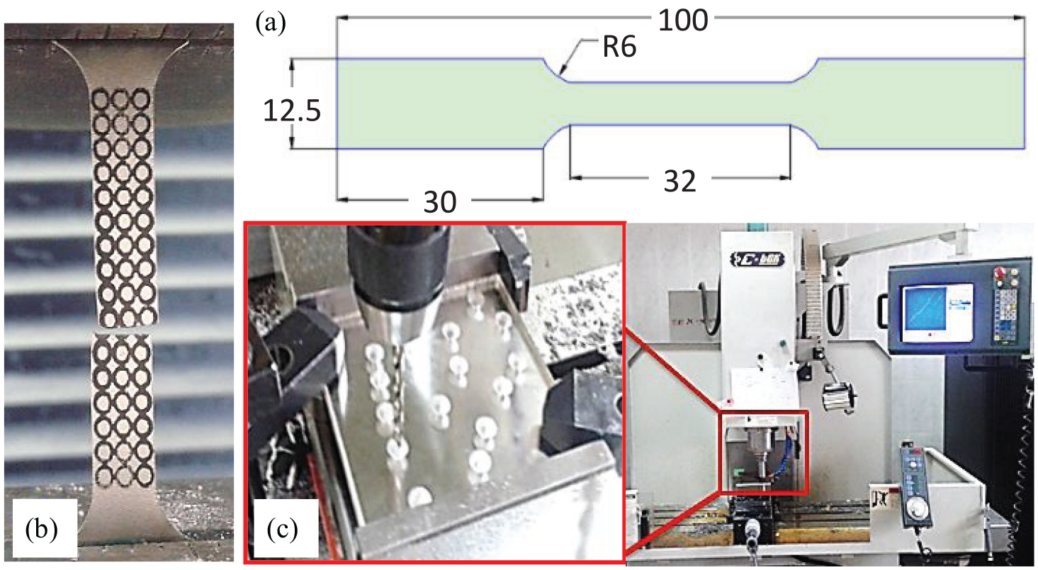
(a) Dogbone specimen, (b) broken specimen and (c) CNC cutting machine.
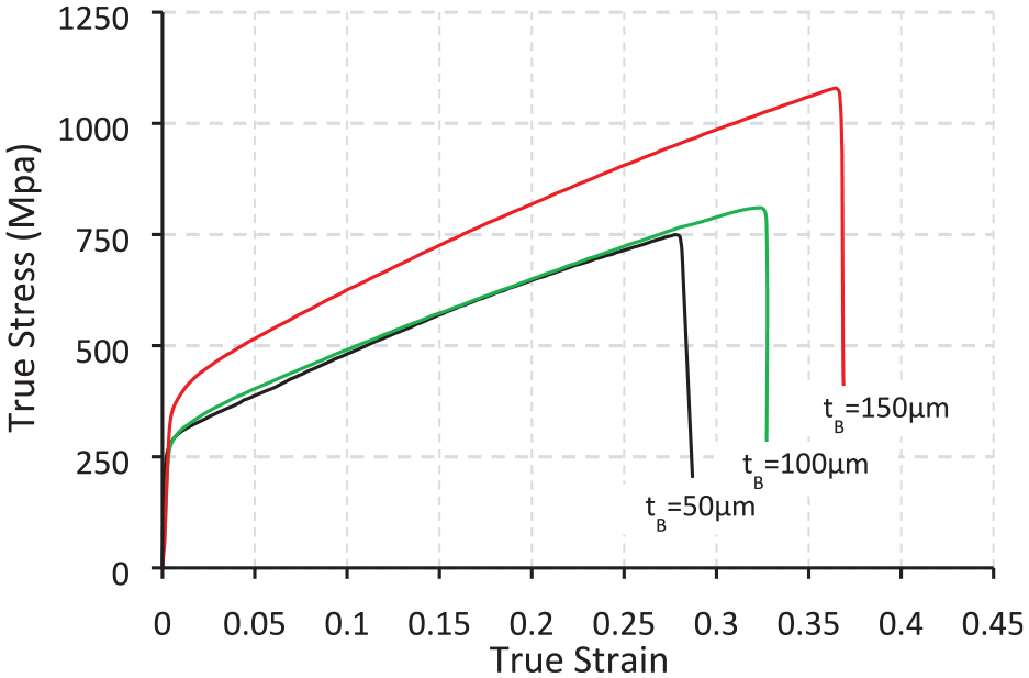
True stress–strain relationship along rolling direction.
Mechanical properties of SS 304 sheets.
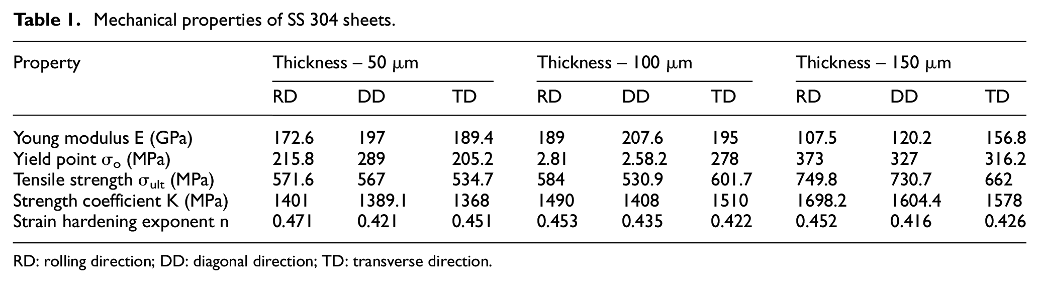
RD: rolling direction; DD: diagonal direction; TD: transverse direction.
Material models used in FE model simulation
Anisotropic behaviour of SS 304 sheet
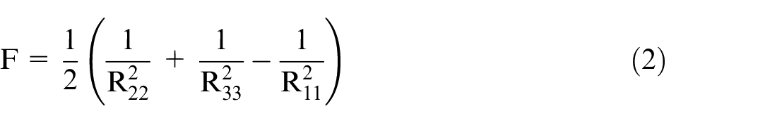
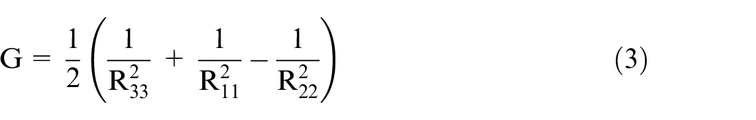
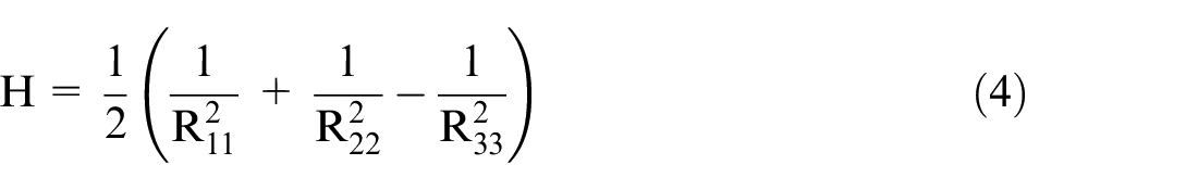
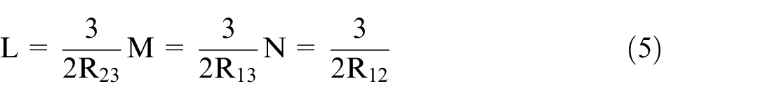
ABAQUS/Standard 6.14 was used to simulate the micro-forming process. The components punch, blank holder and adjustment ring were defined as discrete rigid shell, while blank, floating ring and rubber pad were defined as deformable parts. An elastic–plastic model was used to define the deformation behaviour of SS 304 sheets in the FE simulation. The eight-node linear brick, reduced integration and hourglass control (C3D8R) was used for the sheet material. The boundary conditions of blank are at Z-axis direction as XSYMM (U1 = UR2 = UR3 = 0), while at X-axis direction as ZSYMM (U3 = UR1 = UR2 = 0) (see Figure 3(a)). The plastic anisotropy of SS 304 sheets is introduced using the well-known Hill’s criterion shown below, in which the material constants (F, G, H, L, M and N) are defined in terms of anisotropic yield stress ratios (R11, R22, R33, R12, R13 and R23), as shown in equations (2)–(5)

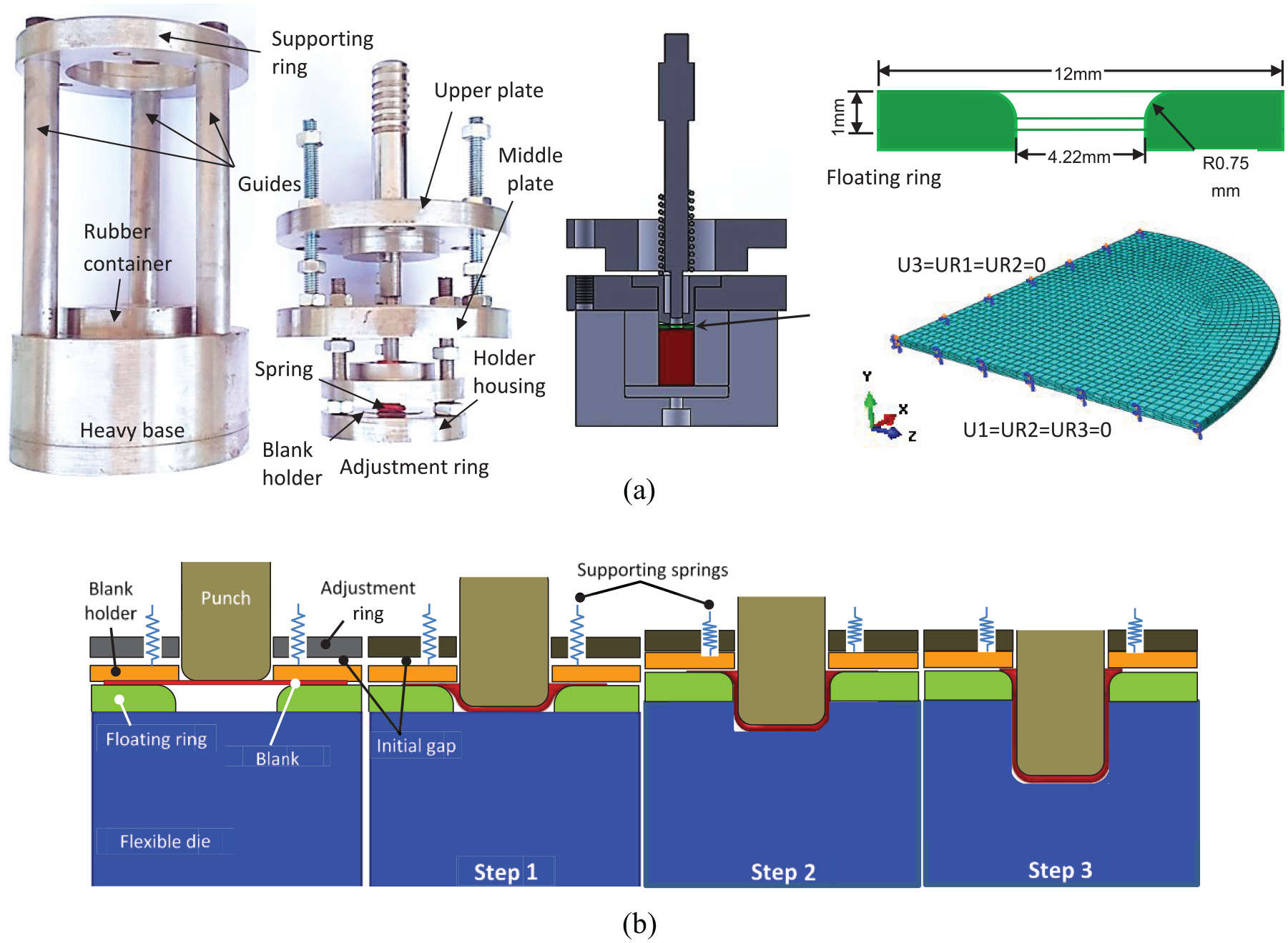
(a) Micro deep drawing setup and (b) proposed forming system.
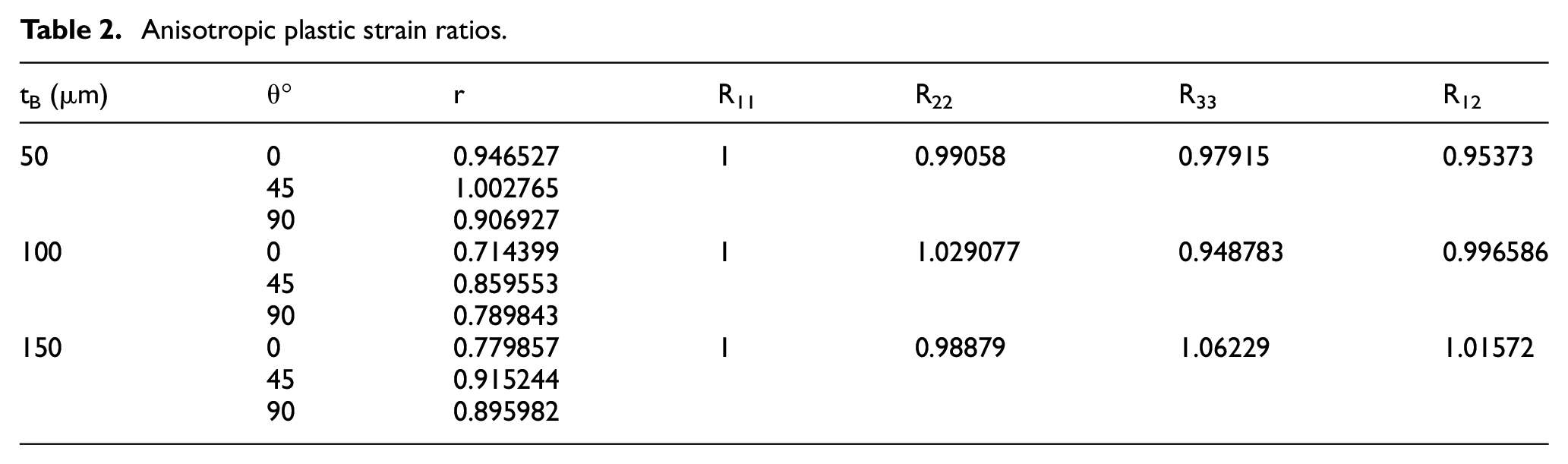
In sheet metal forming, the plane stress conditions are adopted, and consequently only four stress ratios (R11, R22, R33 and R12) are taken into account. 16 Within the FE code ABAQUS, the anisotropic yield stress ratios of sheet metals are expressed in terms of plastic strain ratios (width-to-thickness strain ratios) r0, r45 and r90 along the RD, DD (45°) and TD, respectively, as shown in equation (6). The plastic strain ratios and the anisotropic yield stress ratios required to define the elastic–plastic model are presented in Table 2
Anisotropic plastic strain ratios.
Hyper-elastic model for rubber pad material
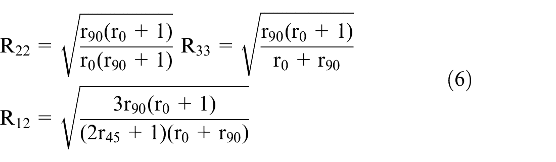
To describe the behaviour of the polyurethane rubber material, the Mooney–Rivlin hyperelastic model was employed. It is known that polyurethane rubber is characterized by a nonlinear stress–strain relation for large deformation, and it is nearly incompressible. The strain energy form of Mooney–Rivlin model is

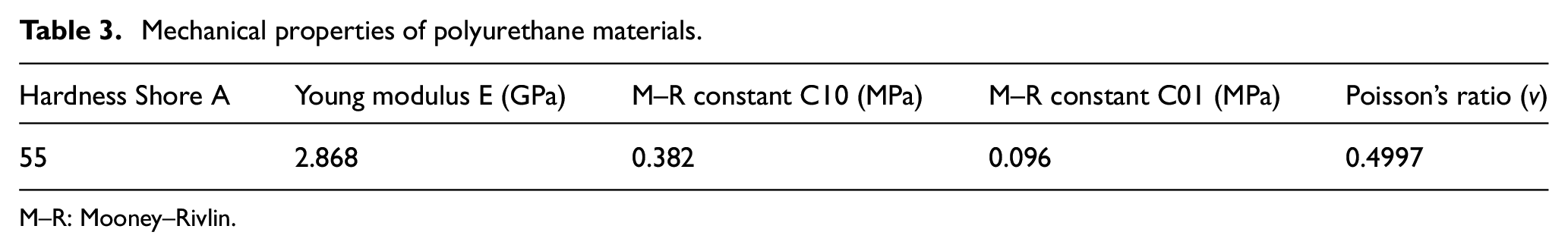
where W is the strain energy per unit of volume, I1 and I2 are the strain invariants and J is the volume change. C10 and C01 describe hyperplastic rubber deformation and D1 indicates the material compressibility. 17 Polyurethane rubber material with 55 Shore A hardness is used for the flexible die and the mechanical properties (hyperelastic coefficients C01 and C10, Young modulus and Poisson’s ratio) are listed in Table 3.18,19 The flexible pad model was built using eight-node linear brick, hybrid, constant pressure, reduced integration and hourglass control (C3D8RH). The boundary conditions at the X-axis and Z-axis directions are similar to that of the blank model. However, U1 = U3 = UR1 = UR2 = UR3 = 0 are used at the side wall of the flexible pad. All the contact pairs simulated in the FE models were defined as surface-to-surface contacts and allow for small sliding between the surfaces. The Coulomb’s model was used to define the frictional behaviour of the contact pairs. The coefficients of friction adopted at the various interfaces are listed in Table 4.
Mechanical properties of polyurethane materials.
M–R: Mooney–Rivlin.
Coefficients of friction at different contact interfaces.
Experiment methodology
For good blanking quality, sets of male and female tools with clearance of 12%–20% of the initial sheet thickness 20 are employed to cut circular blanks from the SS 304 sheets used. Punch-die set is used to cut blanks with 10 mm diameter from different sheet thicknesses, while another tool set is used to provide blanks with different diameters according to the requirements of the size scale factors adopted in this work. The experimental setup presented in Figure 3(a) is utilized to conduct the forming processes and developed especially to meet the simulation requirements. It mainly consists of two groups of components, such as movable and stationary, in addition to the floating ring.
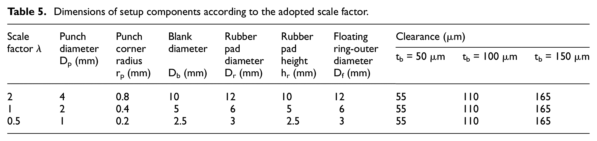
The movable group includes upper plate, rigid punch, middle plate, blank holder, holder housing, adjustment ring, three adjustment studs and supporting spring. The stationary group consists of heavy base, three guides and the supporting ring. Three sets of these components were manufactured with different dimensions correspond the requirements of the size scale (λ = 0.5, 1 and 2) adopted in this work (Table 5). The dimensions of all components corresponding to the three scale factors (λ = 0.5, 1 and 2) are listed in Table 5. The similarity theory is employed in this study for identifying the process dimensions. In addition, the clearance between the floating ring and the rigid punch is designed to be 1.1 times the initial sheet thickness for all cases (Figure 3(a)).
Dimensions of setup components according to the adopted scale factor.
The forming process begins by moving the rigid punch down to form the blank into a shallow shape of depth just equal to the floating ring thickness. Thereafter, the punch is kept moving down pushing the blank into the soft pad and consequently a hydrostatic pressure is excited in the rubber material. As a result, both the floating ring-die and blank holder move up through the initial gap against the supporting spring until the holder reaches the adjustment ring. The hydrostatic pressure continuously increases with punch movement until the cup is completely formed. The forming procedure is presented in Figure 3(b). The undesired issue usually corresponding to flexible deep drawing is the minor wrinkling which are small wrinkles appear at the flange portion during forming stroke. These wrinkles may aggravate during forming process, leading to failure. The function of the floating ring is to overcome these wrinkles as the flange portion will be restrained at the floating ring/blank holder interface. This situation provides appropriate holding force as a result of the increased rubber hydrostatic pressure.
Results and discussion
Effect of sheet thickness
The anisotropic behaviour of SS 304 sheet has remarkable influence on the product profile, as seen in Figure 4. It can be observed that as the cup depth increases the effect of the material anisotropy become clearly higher. The earing phenomenon at the top edges and the flower shape of the flange portion of the formed cups, shown in Figure 4, are mainly caused by material anisotropy. This behaviour indicates that the tensile stresses generated at a particular orientation are greater than others, which implies the reduction in thickness is greater. Thus, the material anisotropy consequently results in variation in thickness distribution (thinning and thickening values). Figure 5 shows wall thickness distribution, along the RD, obtained from experiment and simulation for a cup formed using sheet of 100 µm in thickness. A slight reduction in thickness is observed along the cup bottom, which is attributed to the high friction generated at the blank/punch interface as well as this region is considerably constrained by the punch head and the rubber pad resulting in insignificant relative motion of the blank with respect to these two parts. The curve indicates an increase in thinning along the nose corner and side wall, while a progressive increase in wall thickness is observed at shoulder corner and flange region. It can be deduced that the maximum thinning obtained from experiments and simulation are 13% and 17%, while the maximum thickening are 21% and 26%, respectively.
Cups formed with blank diameter: (a) 9 mm and (b) 10 mm.
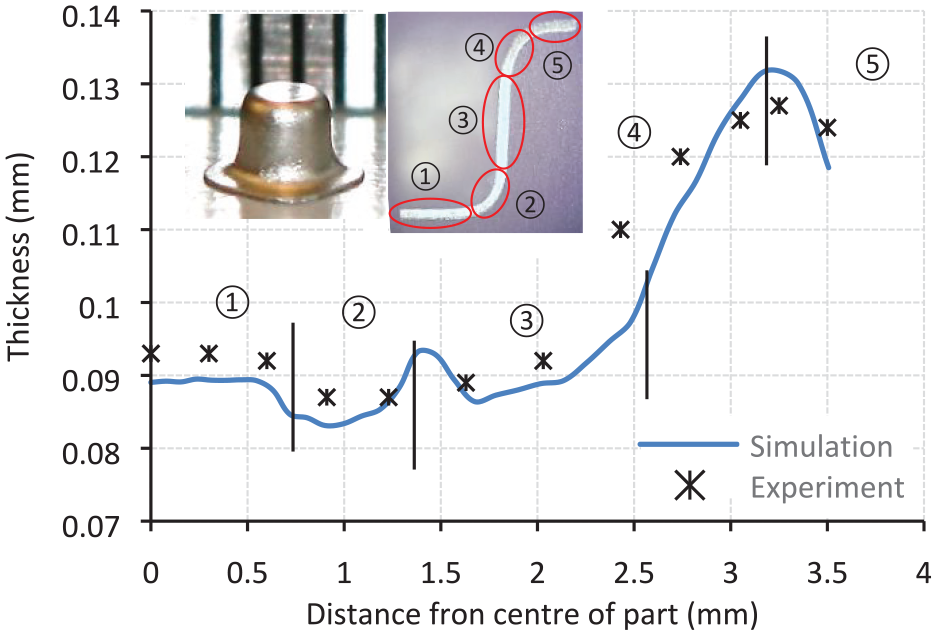
Thickness distribution along rolling direction.
The punch diameter-to-sheet thickness ratio (Dp/tB) has high importance in deep drawing processes as it significantly affects the drawability of sheet metals. 21 The influence of initial sheet thickness is investigated through forming blanks of 50, 100 and 150 µm in thickness according to scale factor λ = 1. That means the Dp/tB ratios adopted in this study are 40, 20 and 13.3. It is very important to carefully specify the initial gap between the floating ring and the adjustment ring to avoid tearing and wrinkling. Owing to successfully production of comparable cups, a number of FE models with various initial gaps were performed for each case in terms of sheet thickness to identify the optimum values. Consequently, the initial gaps of 50, −100 and −400 µm were adopted for 50, 100 and 150 µm blank thickness, respectively. The wall thickness distribution of the cups formed under these conditions have similar trend in regard to thinning and thickening with the same scenario explained above. The results illustrated in Figure 6 indicate a good correlation of the numerical simulations with the physical products in terms of percentages of the maximum thinning and thickening. The highest deviations between the simulation and experimental results are observed for the 150 µm blank thickness in thinning and for the 100 µm blank thickness in thickening. It is determined that the highest error percentage in thinning is 4% and in thickening is 5%. These findings reveal that the cups formed using the current technique have reasonably uniform wall thickness distribution which agree with the previous work. 22 The other important observation is that the difference between the maximum reductions in thickness measured for the different sheets are remarkably inconsiderable. This action refers to the feasibility of this technique in producing micro-cups using various sheet thicknesses.
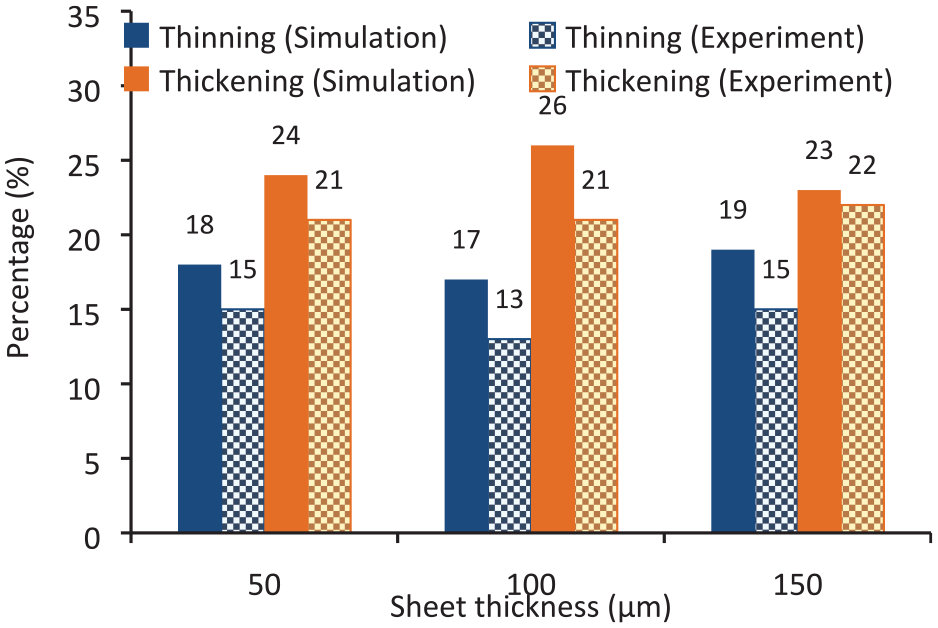
Maximum thinning and thickening of foils with different initial thicknesses.
The results obtained from FE simulations reveal that the punch load increases with forming stroke, as shown in Figure 7. Each curve in this figure has two different slopes, the first one is due to the forming stroke through float ring thickness and the second one is due to forming the shallow cup obtained from the previous step through the flexible die. As a result of reducing the flange area of the blank being formed through the first step, the friction force excited at portion decreases. This action results in reducing the punch load required to complete the forming process, which in return causes the second slope lower than that of the first step. Figure 8 shows clearly the influence of blank thickness on the maximum load values required for successful products. It can be indicated that increasing blank thickness requires an increase in the maximum forming load. The other finding is that the experimental results are slightly greater than that obtained from simulation for the three different cases. This action can be probably attributed to the contact friction force excited at the interfaces of the experimental setup components, which is not taken into account in the FE models.
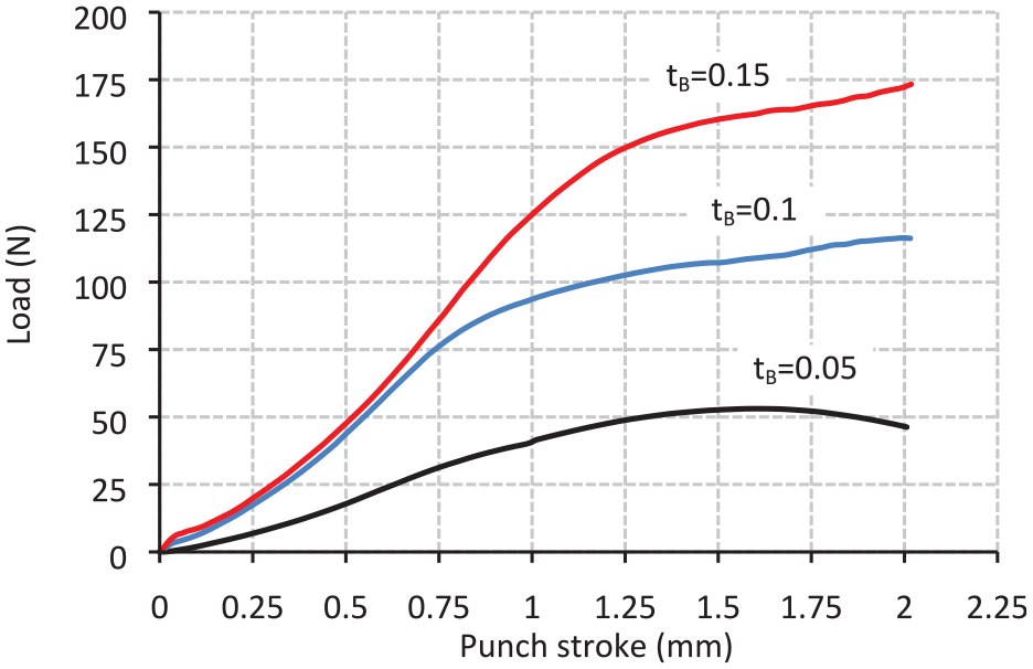
Forming load/punch stroke relationships using different initial blank thicknesses.
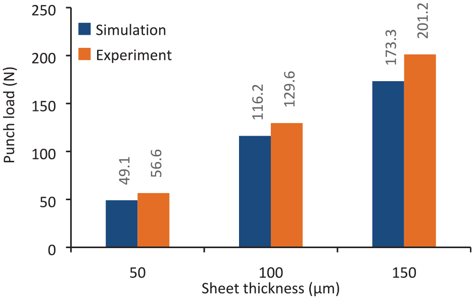
Maximum punch loads for different sheet thicknesses.
Effect of drawing ratio
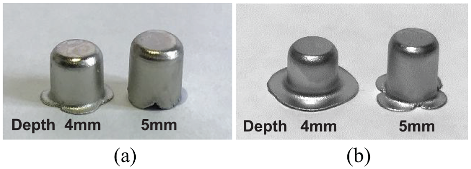
One of the essential measures for sheet formability is the so-called limit drawing ratio. It is important indicator for stability of forming process. At each size scale, blanks of 100 μm in thickness with different diameters were utilized to evaluate the LDR that can be obtained. At the beginning, the effect of blank diameter was investigated according to the conditions corresponding to scale factor λ = 2. Figure 9(a) presents simulated and physical cups formed, with aspect ratio of 1 (product depth 4 mm), using blanks of 8, 9 and 10 mm in diameter. This figure demonstrates stress distribution obtained from FE simulations as a result of the different blank diameters and the initial gap appropriate for each one. Furthermore, a good correlation in terms of geometry profile between the experimental and simulation products can be clearly observed. It can be observed that there is still material remaining at the flange portion of the parts formed with 9 and 10 mm blank diameters. Thus, to form these blanks completely (i.e. drawing ratios of 2.25 and 2.5, respectively), forming processes are implemented again to higher aspect ratio ((approximately 1.5) (see Figure 9(b)). However, to achieve an initial gap of 100 μm for 8 and 9 mm blank diameter cases, 200 μm for the blank of 10 mm diameter is adopted. Figure 10 shows that a slight thinning takes place at cup bottom and then a graduate increase is observed along the side wall and dramatically at the flange portion.
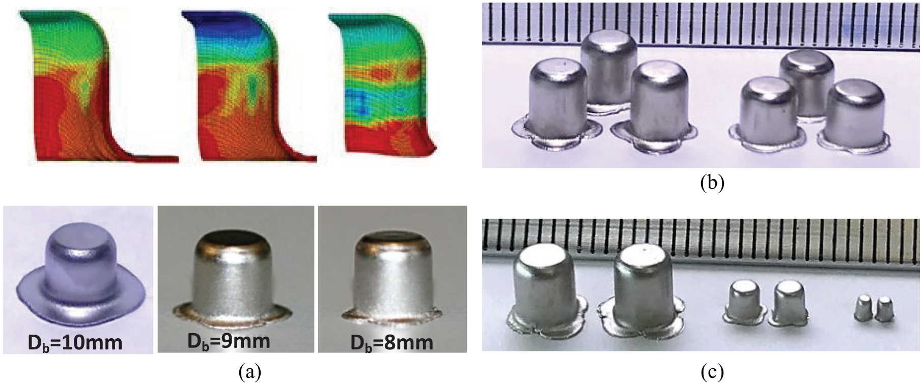
Cups formed using (a) different blank diameters, (b) different aspect ratios and (c) different scale factors.
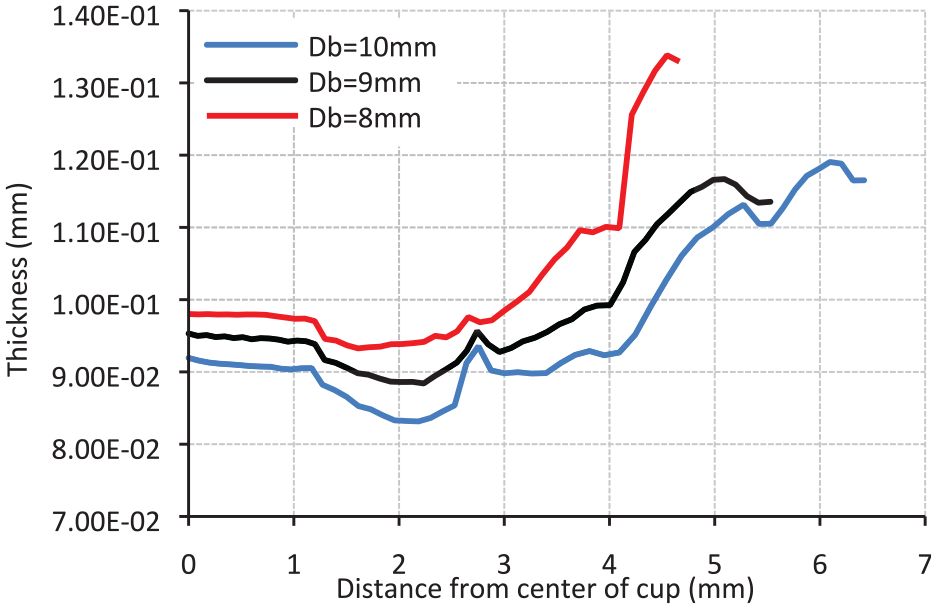
Thickness distribution using different blank diameters.
Figure 11 shows that the maximum reduction in thickness increases as blank diameter increases for both experimental and simulation results. The interpretation of this action is that increasing the flange area of blank causes the holding pressure to increase leading to greater tensile stresses (i.e. more thinning). The results indicates that the maximum reduction in thickness corresponding to blanks of 8, 9 and 10 mm are 6.7%, 11.5% and 17% in simulation and 8.2%, 13.7% and 18.2% in experiments, respectively.
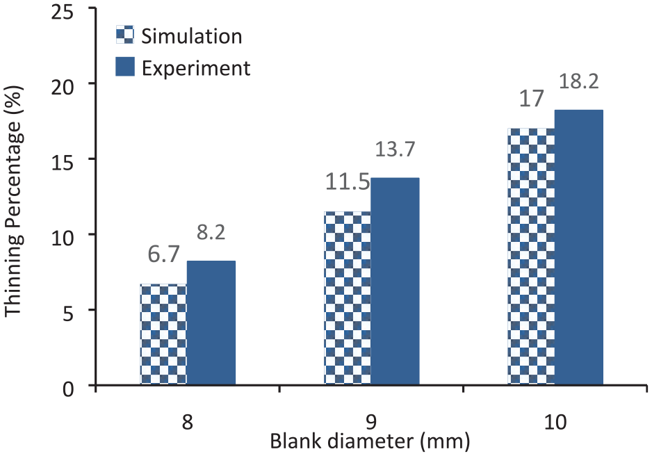
Maximum thinning obtained with different blank diameters.
In regard to forming load distribution, the results reported that the forming load/punch stroke curves for the different blank diameter cases have similar trend, that is, upper curve was obtained for larger blank. It was observed that using blanks of 8, 9 and 10 mm in diameter required maximum loads of 221.9, 340.5 and 287.3 N, respectively. The deviation in load values is not attributed to the difference in initial diameters only but due to the initial gaps adopted for each case as well. The initial gap for both blanks of 8 and 9 mm in diameter is 100 μm, while for 10 mm is 200 μm and this greater gap value therefore leads to a decrease in the maximum load. This study revealed the impact of size scale factor on the limit drawing ratio and product quality. Therefore, the conditions reported in Table 2 are adopted to produce micro-cups (see Figure 9(c)) using blanks of 100 μm in thickness and 2.25, 4.5 and 9 mm in diameter. Consequently, the maximum reduction in thickness obtained is 20.5%, 15.3% and 11.5%, which indicates that the thinning increases as the process are scaled down. This behaviour can be basically interpreted that smaller initial gap is needed when the scale factor goes down (particularly with same sheet thickness) to avoid wrinkling. Furthermore, increasing the miniaturization level results in increase in bending stresses causing the thinning value to increase. Moreover, it is reported that the maximum forming loads of 53.5, 121.3 and 218.4 N were required for completely forming cups under the conditions of size scale factors of 0.5, 1 and 2, respectively. As seen, the load value increases with the increase in the product size which is logically expected. The LDR obtained at the three scale factors adopted in this study are 2.63, at and λ = 0.5 and λ = 1 where the blank diameters are 5.25 and 2.75 mm, respectively, and 2.5 at λ = 2 where the diameter is 10 mm. These results obviously prove the feasibility and capability of the current technique to produce successful micro-cups at different size scales.
Effect of punch nose radius
As mentioned, the intensity of bending stresses significantly increases as the forming process dimensions are minimized for a particular blank thickness. Thus, the radius of punch nose has a crucial impact on the forming process. In this study, the importance of this parameter comes also from the interaction with initial sheet thickness. At each scale factor, forming processes are carried out using rigid punches with various nose radius and blanks with different initial thicknesses. A range of punch nose radius starting from 0.1 mm to a value at which half sphere-shaped cups are obtained, depending on the scale factor considered, is adopted. Table 6 presents the impact of punch nose radius on the formability of SS 304 cups using different sheet thicknesses.
Effect of punch nose radius at different size scale factors.
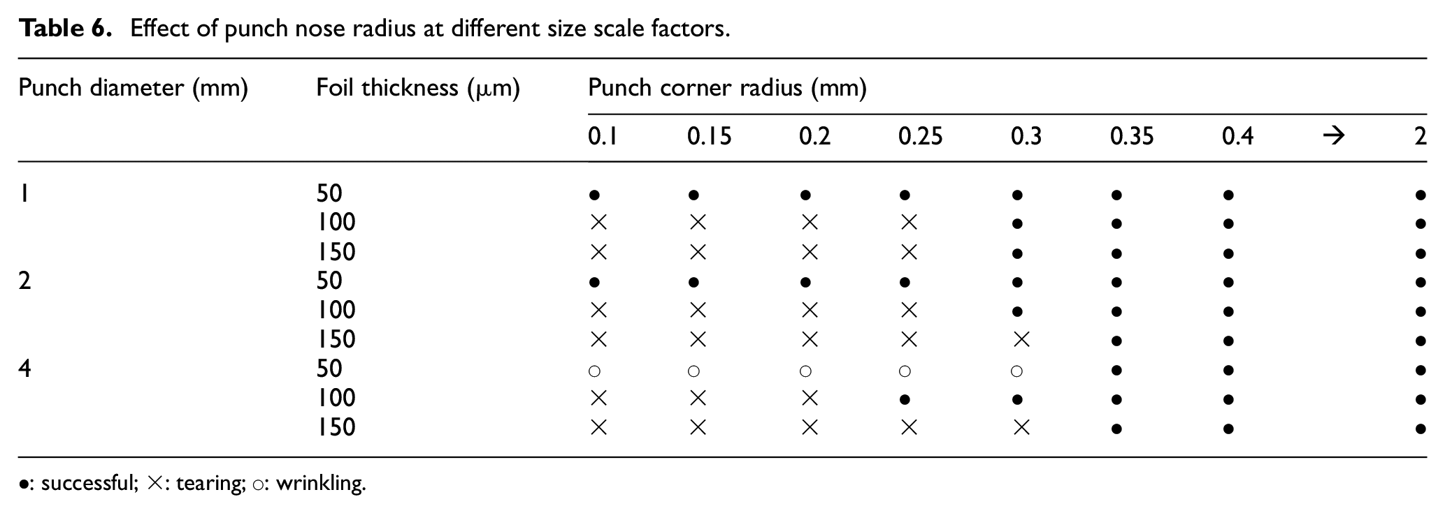
•: successful; ×: tearing; ○: wrinkling.
It is clearly observed that using sheet of 50 μm in thickness results in successful cups at λ = 0.5 and 1, while wrinkled cups at λ = 2 for radius range of 0.1–0.3 mm are obtained. The results showed that the possibility of failure by wrinkling increases as the scale factor increases for a particular range of punch nose radius. The interpretation of this behaviour is that smaller nose radius indicates more material flow into the flexible die resulting in the decrease in flange area. This action causes the friction impact at blank/holder and blank/floating ring interfaces to decrease, leading to wrinkling. The compromise of sheet thickness with blank diameter and initial gap is basically crucial issue in this study. The difficulty and importance of this issue are clearly perceptible when the punch nose radius is changed. In the case of 100 and 150 μm sheet thicknesses, the blank material tends to fail by tearing as the punch nose radius decreases. The range of nose radius at which the tearing occurs is variable depending to the scale factor and sheet thickness adopted in forming process. The results pointed out that the sheet of 100 μm in thickness failed by tearing for the range from 0.1 to 0.25 mm at λ = 0.5 and λ = 1 and from 0.1 to 0.2 mm at λ = 2. However, the tearing occurs for blanks of 0.15 mm in thickness for the range from 0.1 to 0.25 mm at λ = 0.5 and for 0.1 to 0.3 mm at both λ = 1 and λ = 2. It can be concluded that at a particular scale factor, the intensity of bending stresses increases with the increase in sheet thickness for the same punch nose radius. This behaviour interprets why at same scale factor and punch nose radius (for example, λ = 0.5 and 0.1–0.25 mm radius range), the blanks with 50 μm thickness were formed successfully while with 100 and 150 μm thickness failed by tearing.
Rubber pad height
In this study, the influence of height of the flexible pad was investigated via FE simulations. Thus, three models for micro-forming process are built with different pad heights of 5, 10 and 15 mm using the conditions shown in Table 2. At the beginning, the first FE model is achieved with no initial gap for the three pad heights. As a result, successful cups with good quality for the cases of 5 and 10 mm pad height are obtained, and thereafter increasing pad height causes the cups to fail by wrinkling as in the case of 15 mm pad height. In order to produce cups with comparative conditions, in terms of the final profile, initial gaps of −50 and −200 µm are adopted for the pad height of 10 and 15 mm, respectively.
The maximum thinning and thickening of the cups produced under the forming conditions aforementioned are presented in Figure 12. It is clear that there is no effect on the maximum thinning obtained for the three different cases. However, the maximum thickening, measured at the rim of flange portion, increases as the height of rubber pad increases. It is important to remember that both the pad height and the initial gap contributed in these findings.
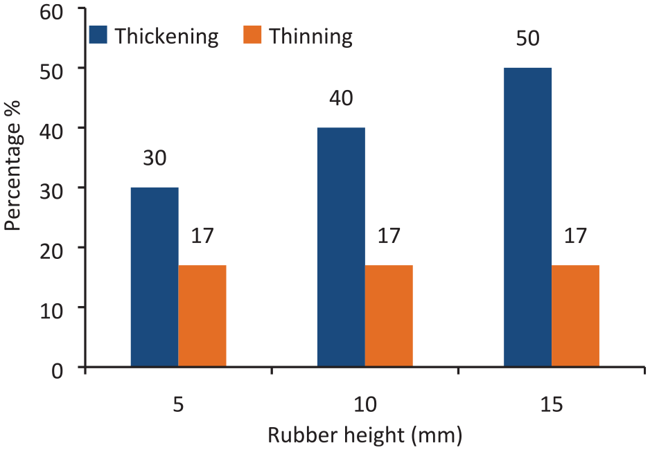
Maximum thinning and thickening with different rubber heights.
The results reveal that the maximum load required to accomplish forming processes using rubber pads with heights of 5, 10 and 15 mm are 285.7, 240.2 and 221.4 N, respectively. It is known that small initial gap results in an increase in the forming force. 22 Though, the results here show that the forming force decreases with increase in the rubber height (i.e. with reducing the initial gap) where the percentage reduction in the forming force of 22.5% is obtained when the rubber height is increased from 5 to 15 mm. This result indicates that the contribution of the rubber height in the influence on punch force is more significant than the initial gap.
Conclusion
This article presents a novel micro flexible forming technique to produce SS 304 cups via a cooperation of floating ring with rubber pad. The process parameters studied in this work are sheet thickness, drawing ratio, punch nose radius and rubber height. The FE models are built using ABAQUS/Standard software. A number of experiments are carried out using a special setup to validate the numerical results. SS 304 sheets of 50, 100 and 150 μm in thickness are employed to form cups using punches of 4, 2 and 1 mm in diameter and the other dimensions are designed according to the size scales adopting in this work. It is observed that sheet thickness has a significant influence on wall thinning and maximum load. As successful cups cannot be formed under same initial gap, it is crucial to compromise between the initial gap and the initial foil thickness to avoid failure wither by tearing or wrinkling. The other finding is that the tendency to fail by tearing increases with the increase in the blank diameter and it is consequently recommended to increase the initial gap so that no wrinkling occurs. Moreover, it is found that the blanks of 50 μm in thickness failed by wrinkling when the scale factor was increased from 0.5 to 2 for punch nose radius from 0.1 to 0.3 mm, while the blanks of 100 and 150 μm thickness failed due to tearing. Therefore, it is crucial to compromise of blank thickness with both size scale factor and punch nose radius. The results detected that the rubber height has no effect on the thinning of cup wall and however increases the maximum thickening.
Footnotes
Declaration of conflicting interests
The author(s) declared no potential conflicts of interest with respect to the research, authorship, and/or publication of this article.
Funding
The author(s) received no financial support for the research, authorship, and/or publication of this article.