
Abstract
Slicing and cutting processing by inner-diameter saw blade has advantages of low cost and convenient adjustment of machine tool. In small size and batch processing, inner-diameter saw blade slicing and cutting is a common-used processing method. However, the wear of inner-diameter saw blade will seriously affect surface quality of workpiece cross section. It is necessary to monitor and evaluate the wear in real time. Based on the short-time Fourier transform, this article introduces a new method for assessing the wear of inner-diameter saw blade. By measuring and analyzing time–frequency characteristics of vibration and machining noise signals, wear is monitored in real time. The results show that it is a good method to monitor the wear of inner-diameter saw blade based on vibration of machine and machining noise signals. In addition, this method has no interference and influence on cutting work of inner-diameter saw blade, which provides a new idea for other forms of tool wear detection in engineering.
Keywords
Introduction
Inner-diameter slicing is a common method for slicing hard and brittle materials. It is widely used in slicing materials such as silicon wafers, optical glass and ceramic materials. Inner-diameter saw blade is a circular disk with a hole in the center and diamond abrasive particles plated on the inner edge. Saw blade is tensioned before machining to improve its stiffness. During machining process, saw blade rotating at high speed is driven by spindle, the diamond abrasive particles act as abrasive, and tool holder, adhesive plate, gasket and workpiece move in an axial and radial order along the blade under the drive of workbench to complete cutting of workpiece.
Hard and brittle materials have characteristics of high hardness, high brittleness, poor thermal conductivity, low fracture toughness, similar elastic limit and strength. Cutting hard and brittle materials perhaps lead to the diamond abrasive particles breaking, blunting even falling off. As cutting processes, these phenomena become more apparent, thereby resulting in serious wear of inner-diameter saw blade. Therefore, monitoring the wear of inner-diameter saw blade is very important to improve processing quality and reduce waste of resources. At present, there are many methods to monitor the wear of inner-diameter saw blade. Measuring changes in cutting force is a common method for monitoring tool wear.1–6 Shao et al. 7 established cutting power model and used it in the strategy of updating cutting force threshold to monitor milling tool wear. Rizal et al. 8 analyzed cutting force signals with I-kaz-based method to monitor tool wear during turning. Huang et al. 9 established an observer model based on uncertain linear systems to measure cutting forces. Tiwari et al. 10 obtained cutting force data and then monitored wear through Kalman filter methodology. The noise signals generated during work is also an important indicator for evaluating tool wear. Based on singular spectrum analysis (SSA), information related to tool wear can be extracted from noise signals. 11 Aggregate spectral difference approach is commonly used to analyze noise signals spectrum change to detect tool wear. 12 Feature extraction method based on time–frequency domain analysis and adaptive kernel principal components analysis (AKPCA) can process noise-reduced audio signals to monitor tool wear. 13 Based on decision tree (J48 algorithm) technology, Madhusudana et al. used discrete wavelet transform (DWT) method to extract a set of discrete wavelet features from the noise signals of milling tool for fault diagnosis of face milling cutters.14,15 Rmili et al. 16 measured vibration signals generated during turning and proposed a mean power analysis to assess and monitor tool wear in real time. Laser Doppler vibration velocimeter (LDV) measures tool vibration displacement with Doppler effect of light wave, collects online data and carries out multiple regression analysis. 17 Monka et al. 18 obtained vibration signals with a three accelerometer and processed them with fast Fourier transform (FFT). Rizal et al. 19 classified and detected tool wear during milling using multi-sensor signals and Mahalanobis–Taguchi system (MTS). Ramasubramanian et al. 20 observed burst-type acoustic emission (AE) signals in the cutter layer to monitor tool wear. Profilometry method is also a common method for measuring tool wear.21,22 The knife-edge interferometry (KEI) uses interference of transmitted and diffracted waves at the edge of cutting edge to measure the wear of cutting tools.23,24 Ghani et al. 25 monitored tool wear by measuring deflection of tool holder in tangential and feed directions. Zhang et al. 26 monitored tool wear by analyzing scratches on the chip surface. It is also a common method to analyze the change of friction electromotive force (EMF), which is resulted from the Fermi effect, caused by tool wear at tool-workpiece interface in frequency domain. 27 Based on the hidden Markov model (HMM), Li and Liu 28 used a multilayer perceptron (MLP) to approximate non-linear function to calculate measured data. In addition, artificial neural network classifiers29–33 are commonly used for data processing in monitoring tool wear. Yen et al. 34 used the FFT to transform AE signals generated on workpiece into frequency domain, and then used the self-organization feature map (SOM) neural network to extract tool wear feature data. The use of Stacked Sparse Auto Encoder (SSAE) neural networks to evaluate different signals from different sensors such as accelerometers, dynamometers and AE can also be used to diagnose tool wear. 35 Different from the above measurement methods, a novel monitoring method is proposed in this article. Vibration signal and noise signal are employed to monitor the wear of inner-diameter saw blade. This monitoring method is mainly used in the field of inner-diameter cutting, meanwhile, also provides idea and reference for tool wear in other machining fields.
In this article, a three-axis accelerometer and a sound signal sensor are used to measure vibration acceleration and machining noise of the machine. A new wear evaluation method of inner-diameter saw blade is proposed, which can quickly and timely monitor the wear of inner-diameter saw blade. The monitoring system consists of three parts: cutting system, signal acquisition system and signal processing technology. New measuring system described in this article can monitor the wear of inner-diameter saw blade without disturbing cutting system. It is suitable for rapid detection of various tool wear in engineering.
Testing method
In this article, experimental test scheme is determined, sensors and other components are selected and installed. An experimental test system for processing is established to measure vibration and noise of the machine during processing of inner-diameter slicer. The workpiece is adhered to gasket when inner-diameter slicer cuts it. At the same time, gasket is bonded to adhesive plate, adhesive plate is fixed on tool holder which is connected with the workbench. The cutting process of inner-diameter slicer is shown in Figure 1. Gasket material used in this article is beech, which belongs to softwood. The hardness of optical glass is very high, even higher than that of most metals. Compared with the workpiece, hardness of gasket material is much smaller, and the impact on cutting process is negligible.
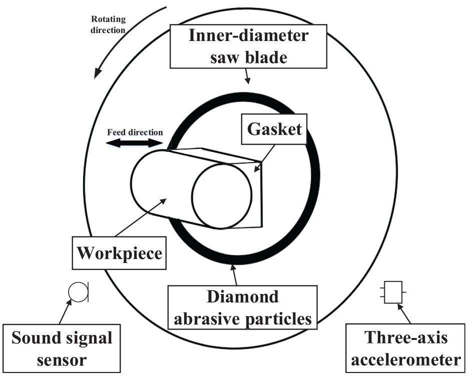
Schematic diagram of inner-diameter slicer.
During experimental test, the measured quantities include vibration acceleration of machine and machining noise. Vibration and machining noise of machine can effectively reflect the working status of inner-diameter slicer and inner-diameter saw blade. Analyzing vibration and machining noise of machine body during processing of inner-diameter slicer can provide a basis for improving working quality and monitoring processing status of the inner-diameter slicer. In addition, vibration of machine body is an important factor affecting the quality of processing, and working noise will affect operating environment and working efficiency. Therefore, detection of vibration and working noise of inner-diameter slicer is very important for the processing.
Establishment of test plan
In cutting test, the main task is to measure and store vibration and machining noise signals during processing. Three-axis accelerometer and sound signal sensor are used to measure vibration acceleration and machining noise of machine body. The data acquisition and storage are completed by data acquisition card and software. When saw blade is cutting a workpiece, three-axis accelerometer can measure acceleration components of three mutually perpendicular directions in space. The coordinate system of these sensors has been determined at the factory. During performing data analysis, in order to unify the direction of each quantity, it is necessary to establish a general coordinate system. This article takes the feed direction of workbench along saw blade axis as the X-axis, the feed direction of workbench along saw blade radial direction as the Y-axis and tangent line that passes through the inner edge of inner-diameter saw blade and workpiece contact point as the Z-axis. The direction of coordinate axis is determined according to the right-hand rule. The cutting test scheme of inner-diameter slicer machining process is shown in Figure 2.
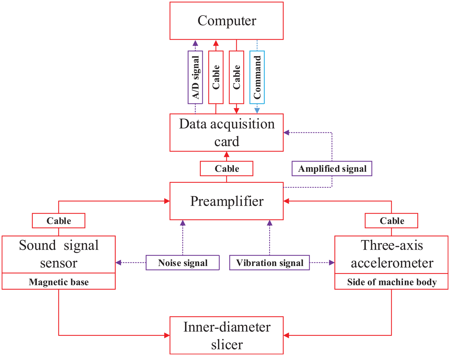
Cutting test scheme.
Measurement setup
In this article, conditions of use and structure of inner-diameter slicer need to be considered comprehensively, in order to choose the appropriate location to install the sensor. The three-axis accelerometer could be fixed on machine body by selecting an appropriate position. There are threaded holes on the side of the body of inner-diameter slicer used for testing, three-axis accelerometer can be installed here. Inner-diameter slicer is placed in the manner shown in Figure 3(b), three-axis accelerometer is installed on the left side of machine body. The approximate position of three-axis accelerometer is indicated in Figure 3(b), and its specific installation is shown in detail in Figure 3(a). According to the installation requirements of sound signal sensor, bracket is processed and fixed on magnetic base. The magnetic base is attached to machine body, which could easily adjust measurement position of sound signal sensor. The three-axis accelerometer and sound signal sensor are installed on inner-diameter slicer as shown in Figure 3(b). The specific location of sound signal sensor and magnetic base is shown in Figure 4.
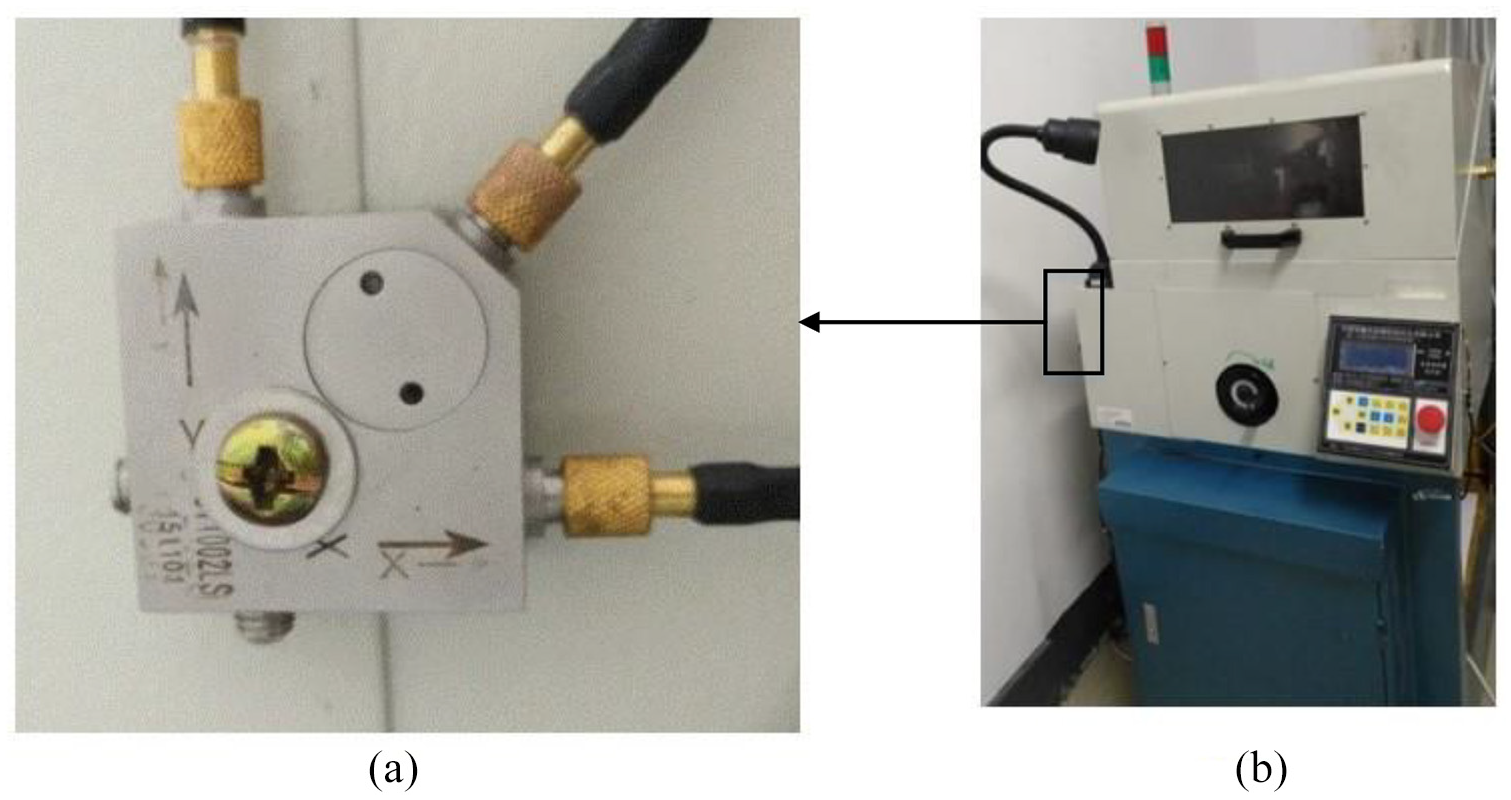
Experimental equipment: (a) three-axis accelerometer fixed position; (b) the whole machine of inner-diameter slicer.
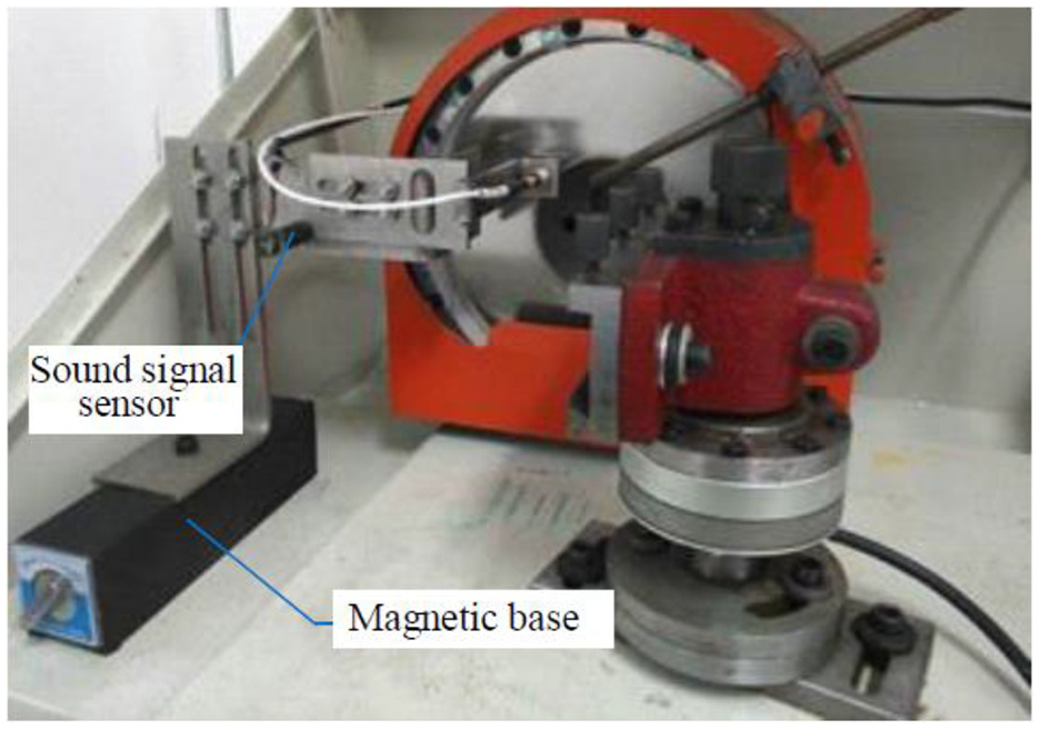
Internal structure of inner-diameter slicer.
Data acquisition and processing
After setting up test system, cutting speed and spindle speed of inner-diameter slicer can be controlled. Due to the limitations of machine itself, cutting speed entered on machine control panel do not indicate the actual cutting speed, but only the relative size of cutting speed. Vibration signal and noise signal are collected by a three-axis accelerometer and a sound signal, and the sampling frequency is 10 kHz. When measuring vibration acceleration and machining noise, the main test steps are as follows:
Before starting experiment, complete the preparation of inner-diameter saw blade tensioning, workpiece clamping, tool setting and so on;
Input cutting speed, thickness, number of slices and other parameters in control panel of inner-diameter slicer;
Enter spindle speed, sampling frequency, sampling time and other parameters in the program, and enter file name;
Run the test program to confirm that spindle is running at the set speed;
Complete the cutting of workpiece;
When sampling is over, program automatically stores the data.
For the vibration acceleration in experiment, the short-time Fourier transform36,37 is used to analyze its time–frequency characteristics, and then changes of various quantities over time are analyzed. For machining noise signals, only time–frequency analysis is performed.
Compared with the method of measuring other physical quantities, vibration signal and noise signal acquisition methods involved in this article have almost no additional impact on cutting system. When physical quantities such as cutting force on workpiece, vibration and axial displacement signal of saw blade are measured, sensors are sometimes placed close to saw blade or fixed on workpiece, which maybe have a greater impact on cutting system to acquiring signals. But signal acquisition method adopted in this article does not over-reform cutting system, so the impact on cutting process is almost non-existent.
Results and discussion
Based on experimental data, this article analyzes the time–frequency characteristics of vibration acceleration and machining noise of inner-diameter slicer when spindle is idling, saw blade works in normal and saw blade is severely worn. The appearance of wear will inevitably lead to a decline in the quality of slice, so the judgment of occurrence of wear is more engineering significance than quantitative analysis of wear. In this article, the wear of inner-diameter saw blade is qualitatively detected and analyzed, and real-time monitoring of wear is achieved based on measured vibration acceleration and machining noise signals of machine body.
Vibration and working noise analysis
Vibration analysis
The time–frequency characteristics of vibration acceleration of machine body when spindle of inner-diameter slicer is idling are shown in Figure 5. Timing starting point in the figure is not consistent with the timing starting point used in analysis of inner-diameter slicer. The frequency components of vibration acceleration in the X-axis and Z-axis directions concentrate below 50 Hz, and amplitude of these frequency components are discontinuous over time. In addition, acceleration in the Y-axis direction also has a component whose frequency is around 200 Hz and the amplitude of this component is intermittently distributed with time. At this time, vibration of machine body is mainly caused by transmission system. The workbench is fed in the Y-axis direction, so frequency components of vibration acceleration in the Y-axis direction are different from the other two directions.
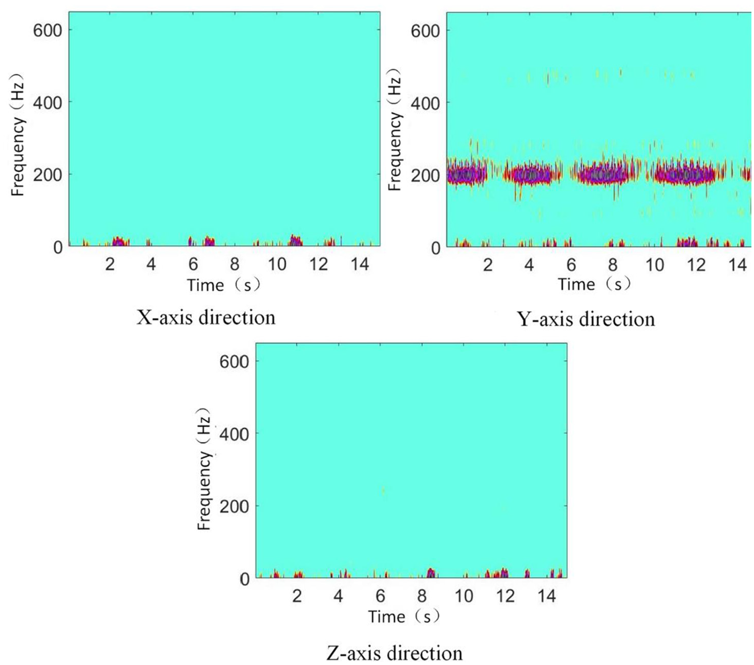
Time–frequency diagram of vibration signal when spindle is idling.
Machining noise analysis
When inner-diameter slicer is idling, the time–frequency characteristics of noise are shown in Figure 6. When spindle is idling, the frequency components of noise signal mainly concentrate below 3000 Hz. The noise signal contains almost all frequency components below 600 Hz, and amplitude of this part of frequency components is also relatively large, it also has large amplitude frequency components around 1200 and 1500 Hz. The noise measured at this time mainly includes working noise of spindle and transmission system, noise caused by spray of cutting fluid and environmental noise.
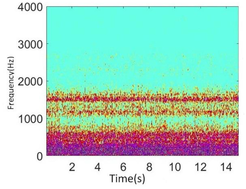
Time–frequency characteristics of machining noise when spindle is idling.
Effect of saw blade wear on vibration and noise
Because the hardness of material cut by inner-diameter slicer is generally high, the wear of inner-diameter saw blade is very common in cutting process. Inner-diameter saw blade rotates at a high speed and withstands large cutting force during cutting process, which will cause diamond abrasive particles on the inner edge of saw blade to break, blunt, and even fall off. Thus, cutting chips are likely to adhere to the side surface of saw blade, causing clogging, friction increase, heat accumulation and temperature increase, and even mechanical wear. After blade edge wears, saw blade will vibrate drastically, which will cause saw blade to hit workpiece and seriously affect processing quality of workpiece. The wear of saw blade is shown in Figure 7.
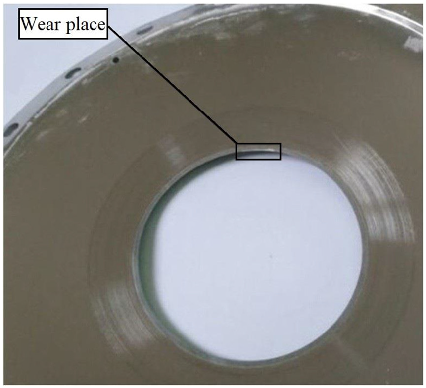
The wear of cutting edge of inner-diameter saw blade.
Optical glass is a common hard and brittle material, and inner-diameter slicing is a common processing method for it. The optical glass is selected as the material, and different characteristics of each quantity are compared before and after saw blade is severely worn. Because of tension of saw blade, clamping condition of workpiece and differences in mechanical properties of workpiece material, the time–frequency characteristics of noise and body vibration during each cutting process are slightly different. Therefore, based on multiple cuts, for situation before and after severe wear of inner-diameter saw blade, two cutting processes are selected, respectively, to compare different characteristics of saw blade before and after wear. The optical glass rod with a diameter of 20 mm is used for cutting. The processing speed of inner-diameter slicer was 3000 r/min and the cutting speed is 20.
Vibration acceleration before and after wear
The time–frequency characteristics of vibration acceleration of machine body when inner-diameter saw blade works in normal are shown in Figure 8. The time–frequency characteristics of vibration after severe wear are shown in Figure 9.
Time–frequency characteristics of vibration acceleration signal when saw blade works in normal: (1) first set of selected data; (2) second set of selected data.
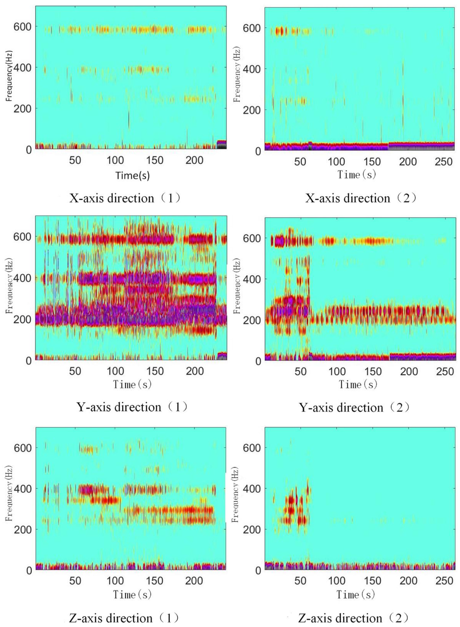
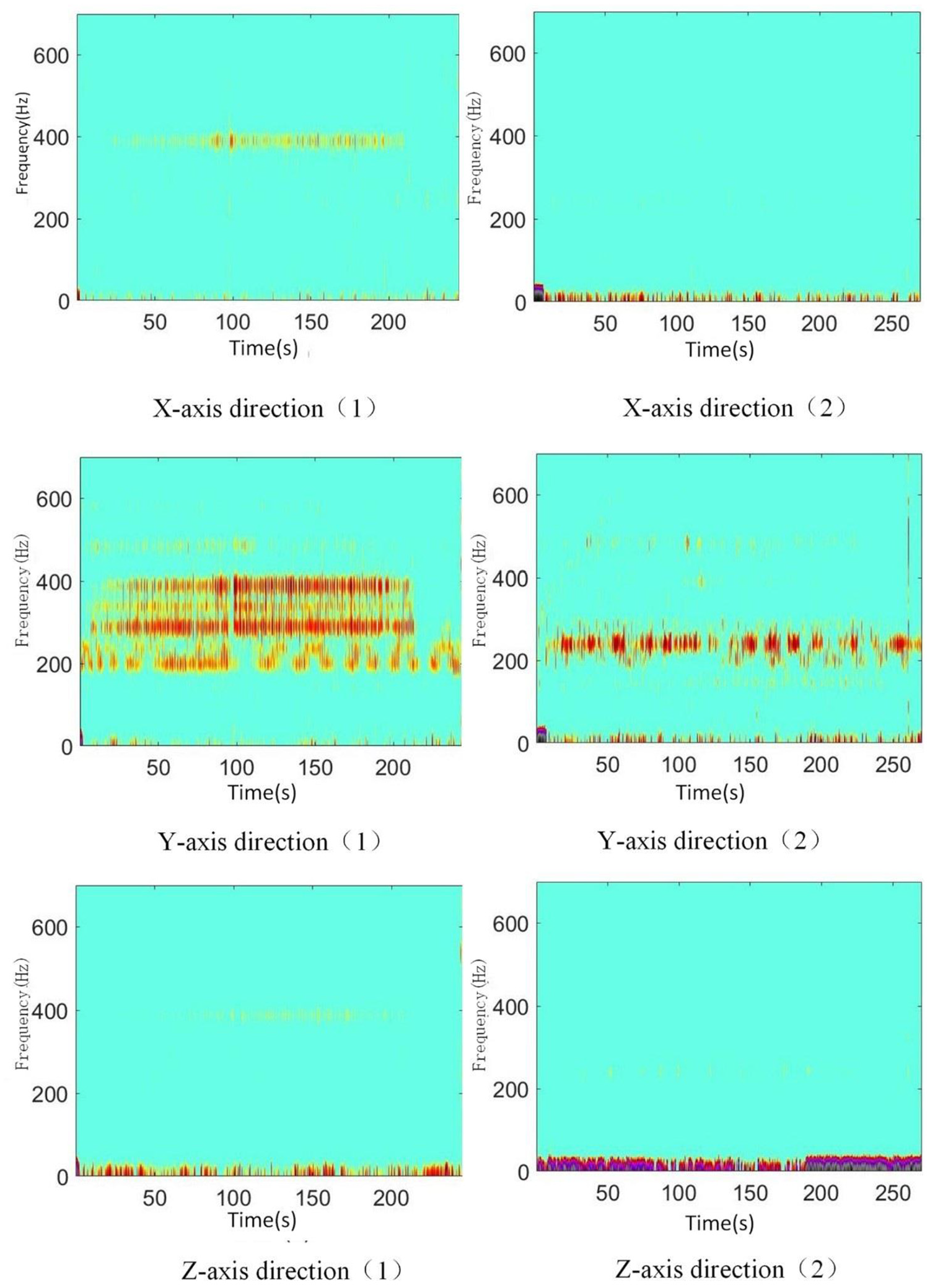
Time–frequency characteristics of vibration acceleration signal when saw blade is severely worn: (1) first set of selected data; (2) second set of selected data.
When inner-diameter saw blade works in normal, frequency components of vibration in the Y-axis direction are the most complicated. Among the vibration accelerations in three directions, amplitude of frequency components below 50 Hz is relatively large. In the Y-axis direction, there are frequency components higher than 50 Hz which have larger amplitude. These frequency components sometimes appear in the other two directions. Currently, the interval between horizontal stripes on time–frequency graph is obvious, and frequency components with larger amplitude appear at intervals.
After blade edge is severely worn, the vibration amplitude of machine body in the Y-axis direction is greater than the other two directions, and amplitude of frequency components below 50 Hz is still relatively large in three-direction vibration acceleration. These characteristics are the same as when inner-diameter saw blade is working in normal. However, the amplitude of some frequency components suddenly increases at some point during processing, and after a short period of time, their amplitude suddenly decreases again. On time–frequency diagram of vibration after saw blade is worn, interval between horizontal stripes becomes blurred, and some short horizontal stripes appear, which is especially obvious in the Y-axis direction.
Processing noise before and after wear
During cutting process, vibration and noise signals generated are large, environmental noise and electrical noise are very small instead. The influence of environmental and electrical noise on measured signal is negligible, so they are not considered. The time–frequency characteristics of machining noise when inner-diameter saw blade works in normal are shown in Figure 10(a). Although frequency components of noise were complex, amplitude of specific frequency components is significantly higher than others. This phenomenon continues from the beginning to the end of processing, and several dark horizontal stripes are formed on time–frequency diagram. The color of these horizontal stripes gradually becomes lighter from the bottom to the top of graph, indicating that among these frequencies, the higher the frequency, the smaller the amplitude. Figure 10(b) is a time–frequency diagram of machining noise after severe wear of inner-diameter saw blade. At this time, horizontal stripes corresponding to high-frequency frequency components on time–frequency graph of machine noise become unclear, and at the same time, obvious vertical lines appear.
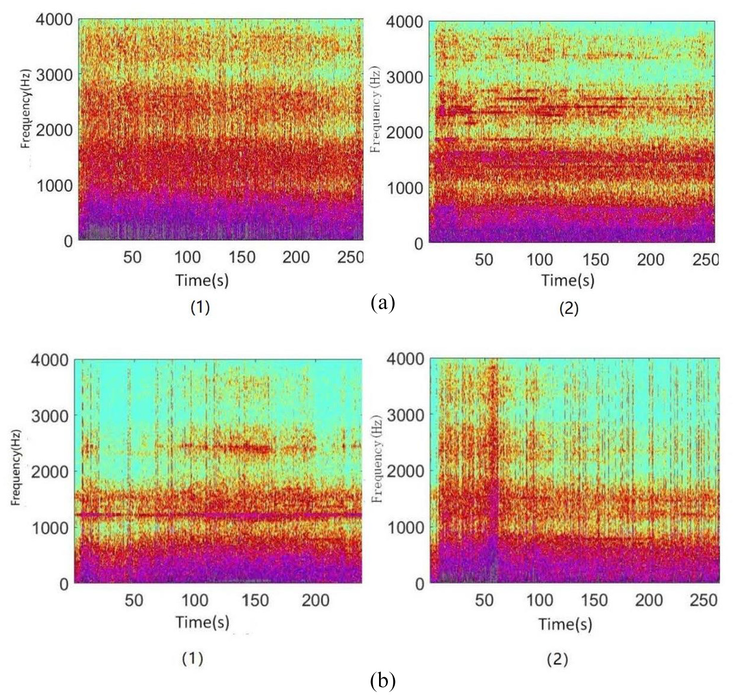
Time–frequency characteristics of machining noise: (a) during normal operation of saw blade; (b) after severe wear: (1) first set of selected data; (2) second set of selected data.
Further discussion on saw blade wear
After cutting edge of saw blade wore, wear of each part is different, so the wear of inner-diameter saw blade continues to develop during cutting process. In this way, during the cutting of workpiece by saw blade, the change of sawing force becomes disordered. Frequency components and amplitude of vibration acceleration would change abruptly, the boundaries of horizontal stripes on time–frequency graph would be blurred and some short horizontal stripes would appear at the same time. Since workbench is fed along the Y-axis direction during cutting, stiffness of saw blade in the Y-axis direction is relatively large, so this phenomenon is most obvious in the Y-axis direction. The frequency components of time–frequency characteristics of machine body vibration in the Y-axis direction are more complicated than the other two directions, so they are more authentic and persuasive in judging the wear of inner-diameter saw blade. Compared with time–frequency characteristics of normal operation, if amplitude of vibration in the Y-axis direction increases sharply, a frequency component in the range of 400–600 Hz appears, and an obvious horizontal stripe appears near 600 Hz, and the interval between horizontal stripe blurs, and some short horizontal stripes appear at the same time, they prove that inner-diameter saw blade has been severely worn, and blade needs to be replaced in time to ensure normal operation of inner-diameter slicer.
When inner-diameter saw blade works in normal, the force changes of saw blade and workpiece are relatively gentle, cutting proceeds are smooth, frequency components and the amplitude of noise change slowly with time, so horizontal stripes appear on time–frequency diagram. The wear failure generally random appears at a certain position of blade edge, and would continue to develop as cutting progresses. In this way, the forces on inner-diameter saw blade and workpiece would change drastically during cutting process. Correspondingly, frequency components and amplitude of machining noise also change drastically over time. On the machining noise time–frequency characteristic diagram, there would be a phenomenon that horizontal stripes become blurred and vertical stripes occur. Therefore, compared with normal work, high-frequency components above 1000 Hz on time–frequency diagram of machining noise become blurred, and obvious numerical lines appear, this is also a sign of severe wear of inner-diameter saw blade.
Conclusion
In this experiment, several sets of experimental measurements are carried out, and the results prove that vibration acceleration and machining noise of inner-diameter slicer have good correspondence with the wear of inner-diameter saw blade. The blurring phenomenon of horizontal stripes and the appearance of specific stripes on time–frequency diagram of vibration and processing machining reflect the wear of inner-diameter saw blade in time, and the wear condition can be inferred based on this in engineering.
The signal acquisition method adopted in this article does not over-reform cutting system, and the monitoring method monitors wear condition of inner-diameter saw blade by detecting process variables generated during the operation of inner-diameter slicer, which do not have an additional impact on cutting process. As a result, the impact on cutting process is almost non-existent.
This measurement method provides a new idea for detection and monitoring of the wear status of saw blade, and is of great significance for monitoring wear status of saw blade, ensuring the quality of processed parts, and reducing the cost of processing waste in practical applications.
Footnotes
Declaration of conflicting interests
The author(s) declared no potential conflicts of interest with respect to the research, authorship, and/or publication of this article.
Funding
The author(s) disclosed receipt of the following financial support for the research, authorship, and/or publication of this article: This work was supported by the National Natural Science Foundation of China (NSFC) (grant number: 51675215) and the Capital Construction Funds within Budget for Industrial Technology Research and Development of China Jilin Province (grant number: 2019C037-5).