
Abstract
Vacuum electron beam welding is widely employed for the welding of titanium alloys using different beam oscillation patterns. Since these patterns influence the physical phenomenon in the weld pool, its effect on the microstructure, texture, mechanical properties and residual stresses is of prime interest. In order to understand this influence, electron beam welding was used to prepare Ti-5Al-2.5Sn weldments using beam oscillations of triangular and rectangular waveform. It was observed that a change of welding pattern had a strong influence on the residual stresses, impact properties and texture of weld zone while tensile properties were not significantly affected. A partial martensitic transformation was observed in both the triangular and rectangular waveform of oscillations. An increase in alpha lathe width was observed in the fusion zone and similar strength of the rectangular pattern as compared to triangular pattern. Despite of this, the observed higher Vickers hardness of the fusion zone of rectangular pattern as compared to triangular and no-oscillation was attributed to texture strengthening using rectangular waveform.
Introduction
Titanium and its alloys are used extensively in various industries due to their highly desirable mechanical and physical properties.1–4 The properties of titanium and its alloys which are favorable for many critical applications are high corrosion resistance, better strength, low specific weight, creep resistance, biocompatibility and excellent fatigue behavior.1,5,6 Due to these beneficial properties, titanium and its alloys are employed in military, aerospace, marine, medical, chemical and automotive applications.1,7–9 These important applications require the alloy to be performance-optimized and weight minimized. 10 Previously, riveting was used for joining process in the aerospace industry; however, in recent times, the trend has shifted toward welding. 11 Ti-5Al-2.5Sn is used in critical applications compared to other alpha titanium alloys due to its superior weldability, fracture toughness and ductility at low temperatures and therefore this alpha alloy is preferred over other alpha titanium alloys. 12
Due to the higher demand for titanium and its alloys, several types of welding processes including laser beam welding (LBW), tungsten inert gas (TIG) and electron beam welding (EBW) have been used for producing quality joints.10,13 However, in the case of titanium, additional care must be taken of weld pool due to the reaction susceptibility with surrounding gases, i.e., hydrogen, oxygen, nitrogen.10,13,14 Therefore, for titanium alloys, EBW is preferred as the welding takes place in vacuum, hence no contamination from the surrounding. The vacuum in EBW isolates the weld pool from the atmosphere which leads to weldment with no unwanted contamination. 14 A comprehensive review of EBW process is given by Vadolia et al. 15 EBW is used to weld titanium alloys due to concentrated energy, high power density and more weldable thickness range.16,17 In EBW, variable sizes and geometries of the work pieces can be easily welded due to the greater working distance as compared to other welding techniques, that is, TIG and LBW. 18 The requirement of high vacuum had limited the use of EBW commercially; however, the technological developments with time has made it possible to use this process at medium and low vacuum, which has drastically increased its usage in industrial applications. 19
EBW is widely employed in important industries such as aviation, automotive, medical to manufacture high-performance components such as turbocompressors, turbine blades and housings, high current flexible connectors, toothed gear elements in artificial limbs, bearing sleeves. A key research aspect in these applications is to optimize the EBW process so that desirable properties can be produced in the industrial components. For instance, by focusing the electron beam, it can not only be used for rapid prototyping, but also in repair welding, for example, rotor of a gas turbine, compressor blades, engine chamber and so on.20,21 Due to the flexibility in EBW process, the layer thickness and fusion penetration can be adjusted in order to minimize the distortions in repair weldments. Not only is electron beam used for joining but also used for industrial heat treatment such as hardening. 21 EB is used to harden a number of important alloys such as unalloyed structural steel, tools, gray cast iron. Furthermore, EB is also used in industries for surface modification of high-performance titanium alloys without the formation of porosity at the surface. 22 Another useful application of EB is in the surface engineering industry in which surface texturing via EB is used to improve biocompatibility and for joining of plastics with metal.23–25
In EBW, the beam properties can be enhanced using different predetermined oscillation patterns such as circular, sinusoidal, elliptical and so on. Contrary to linear electron beam, the oscillating EB is designed to develop a kind of churning action of liquid in the molten weldment. This churning action leads to greater mixing, reduces segregation and results in a more uniform composition and structure of the weldment. 26 In the beam with oscillation, the directed flow due to Marangoni convection in the molten pool leads to directional properties. 27
Hao et al. 28 reported the effect of oscillation frequency and amplitude on the fusion-zone morphology in LBW of 304 SS and concluded that with an increase in frequency or amplitude the heat input in weldment decreased, changing the weld mode from key-hole to conduction. Oscillating beam moves faster than non-oscillating beam requiring higher current for full penetration of the weldment. Therefore, the input current for oscillating beam can be taken as base value for the heat input rate because the oscillating beam heat input will be sufficient for non-oscillating beam which requires less heat input. It has also been observed that the thickness of the plate greatly affects the homogeneity and defects in the weldment structure. Fu et al. 29 and Babu et al. 30 reported the effect of the beam oscillation on Ti-6Al-4V weldments and found the mechanical properties such as fatigue life and ductility to be better with an oscillating beam.
Babu et al. 7 performed EBW on Ti-6Al-4V titanium alloy using different oscillating beam patterns, i.e., sinusoidal, elliptical, square and triangular. They only compared the effect of oscillating the beam with that of no-oscillation on the tensile properties, temperature and the microstructure. They concluded that beam oscillation in general resulted in higher ductility and lower strength as compared to non-oscillated beam. However, they did not specifically compare the influence of different waveforms on the weldment properties of titanium alloy. The evolution of microstructure in the weldment during welding process is closely related to the variations in the texture. Bache and colleagues31,32 discussed the effect of texture on the impact and tensile properties in detail. Tensile properties such as ultimate tensile strength, ductility and modulus were affected with variation of texture in the weldment. 31 Thus, it is important to analyze the texture of weldment to study their mechanical properties. In the previous work carried out by the authors, a detailed study of the microstructure, mechanical properties, residual stress distribution and distortions was carried out for the non-oscillation mode of EB welding of Ti-5Al-2.5Sn alloy. 1 Considering all the aforementioned aspects, the present study is focused on characterization of the EB weldments using triangular and rectangular waveform of beam oscillation and their comparison with the non-oscillation mode from the authors’ previous work. 1 Residual stresses, micro-hardness, tensile and impact properties of the welded Ti-5Al-2.5Sn alloy were correlated with the physical phenomenon using textural and microstructural changes in the weld zone.
Experimental procedure
Material and welding conditions
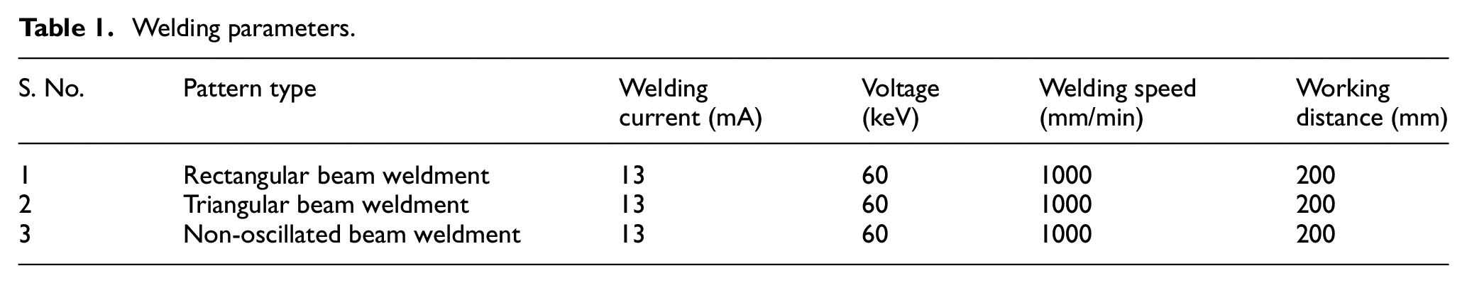
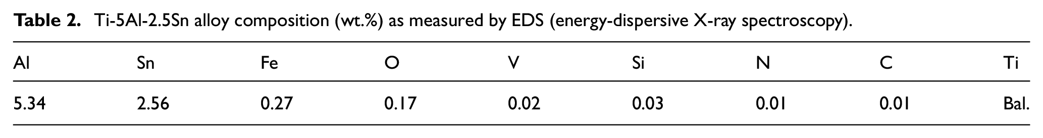
EBW oscillation mode was used for welding the Ti-5Al-2.5Sn alloy in two patterns, i.e., rectangular and triangular. The schematic of EBW is shown in Figure 1, while Figure 2 shows the schematics of the welding patterns. All the welding parameters were kept the same for both the beam patterns and non-oscillated beam weldment as shown in Table 1. Ti-5Al-2.5Sn alloy plates were prepared from the received sample and were used for EBW, with the dimensions of 100 × 75 × 1.6 mm. The plates were annealed at 750 °C for 2 h in inert atmosphere to remove any residual stresses prior to welding process. Surface of the joint was mechanically wire brushed and subsequently polished using the grit paper. The plates were cleaned with acetone prior to the welding process. The two plates were clamped together tightly with no gap between them. Table 2 shows the chemical composition of the alpha Ti-5Al-2.5Sn alloy, which was used in present study. Figure 3 shows the image of the final weldments obtained after the EBW process was performed at different scanning patterns.
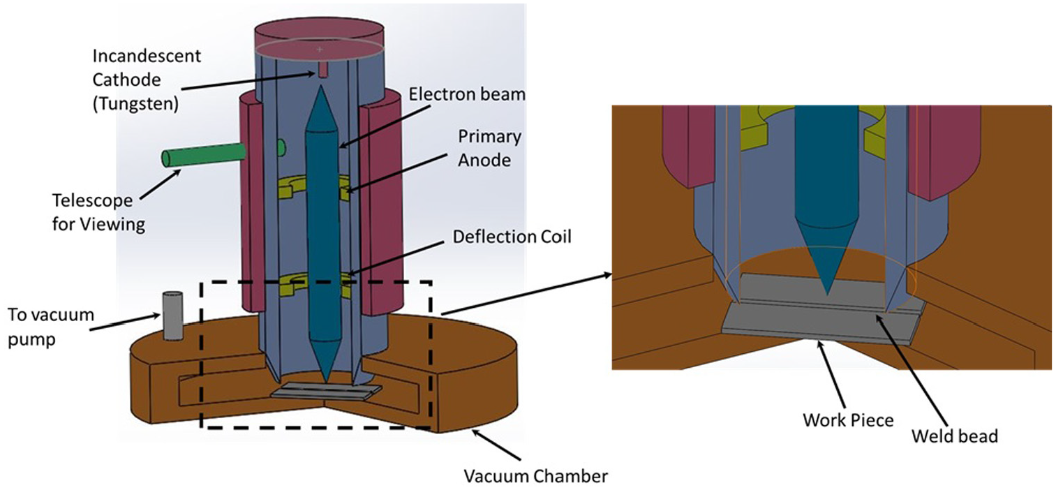
Schematic of EBW setup.
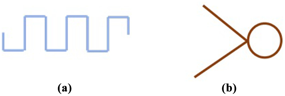
Schematics: (a) rectangular pattern; (b) triangular pattern.
Welding parameters.
Ti-5Al-2.5Sn alloy composition (wt.%) as measured by EDS (energy-dispersive X-ray spectroscopy).
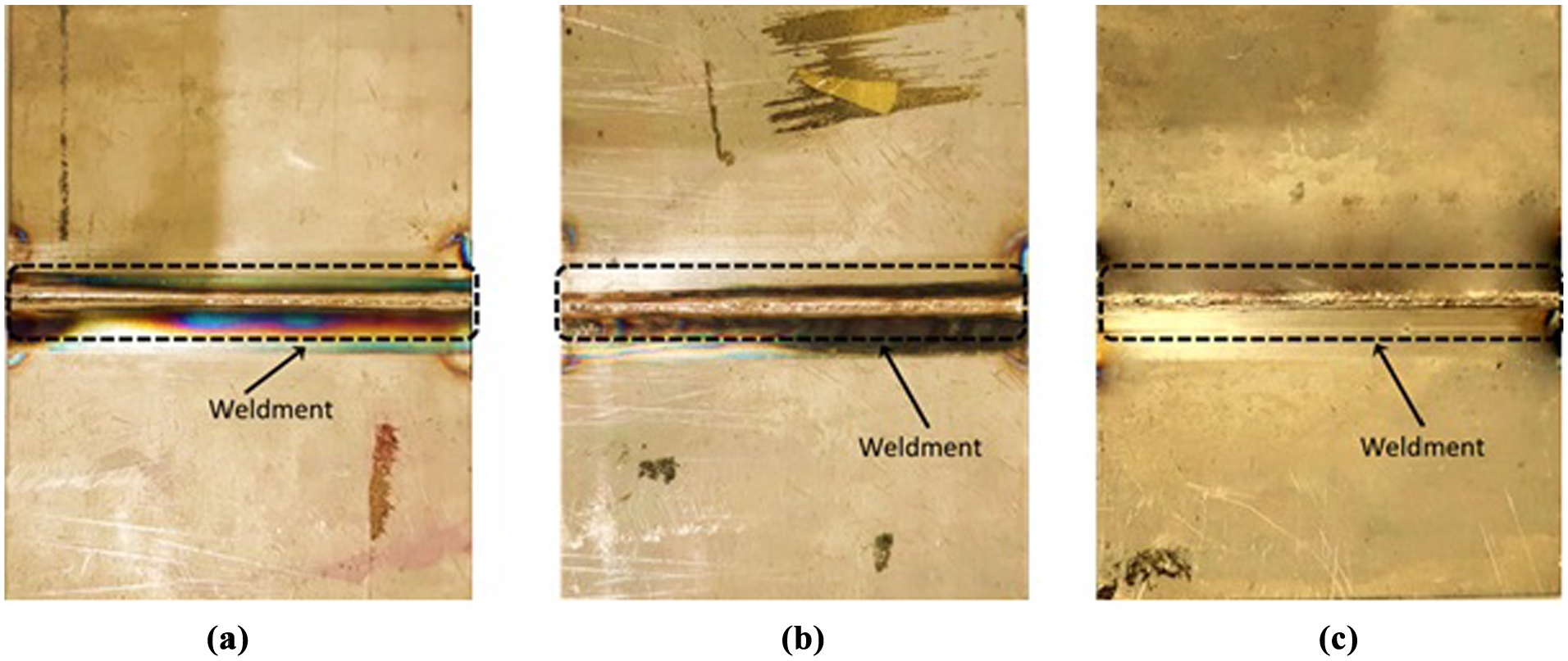
(a) Rectangular pattern plate; (b) triangular pattern plate; and (c) non-oscillated beam plate.
Two different patterns using the oscillating beam in EBW were used, and the welding was performed at 60 kV. During the welding process, electron beam was solely focused on the welding line of the base metal (BM), at a constant current of 13 mA a constant welding speed of 1000 mm/min. The current was maintained constant since the both joining plates were of same alloy, in order to keep the similar heat transfer rate on both the sides. All the three welded plates were studied after welding and were evaluated on the basis of developed microstructure, residual stresses and mechanical properties, and the details are provided in the following sections.
Microstructure
To observe the microstructure of both the weldments, samples were cut perpendicularly to the weldment bead using wire electric discharge machining (EDM) as shown in Figure 4. After machining, the samples were mounted using epoxy for metallographic examination. This was followed by grinding using SiC grit papers from 240- to 4000-micron size. Subsequently, the samples were polished using 0.05-µm alumina paste using a non-ferrous velvet cloth. After polishing, samples were etched using the Kroll solution (2% HF in distilled water). The microstructure of specimens was studied using the polarized light with a filter using Olympus BH2-UMA optical microscope.
Schematic diagram for the samples prepared for optical microscopy.
The residual stresses generated in the weldment were measured using Hole-drill strain measurement method. A strain rosette was placed at 5-mm distance from the weld centerline for measurement for all specimens, and a hole was drilled in the center of the strain gauge as shown in Figure 5. The strain data were recorded using multi-channel data acquisition system which was connected to the strain gauge in which the hole was drilled. The measurements were taken continuously and at an incremental depth of 0.4 mm, starting at the surface. After acquiring the data, transverse (perpendicular to welding direction) and longitudinal (parallel to welding direction) residual stresses were calculated using the H-drill software. The hole drilling to measure residual stresses was done immediately after welding, followed by other characterization techniques.
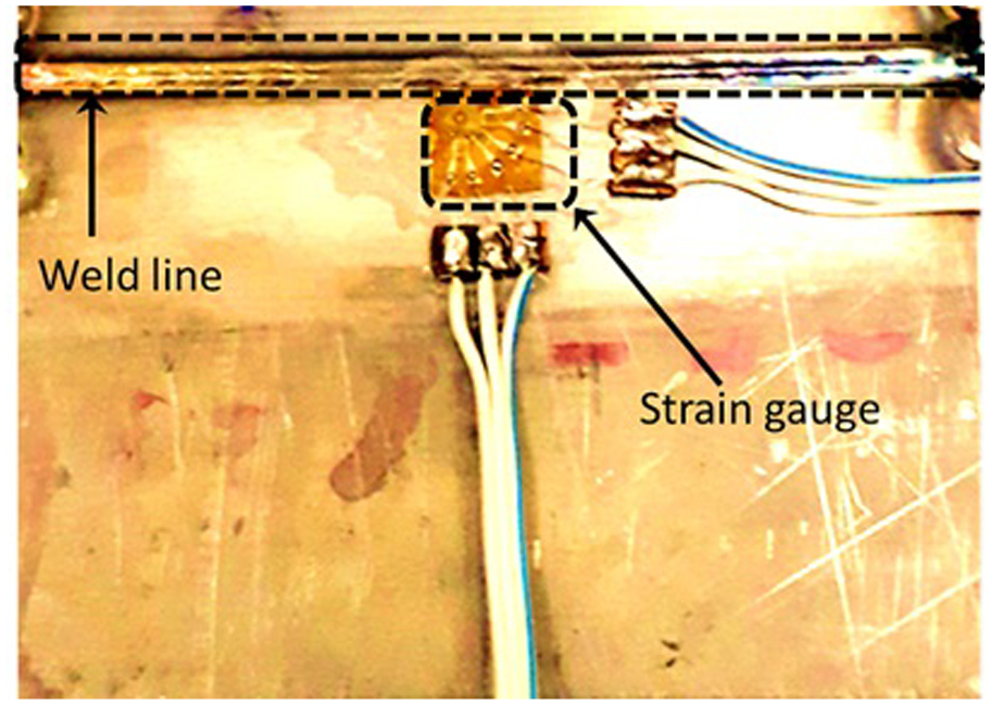
Position of strain gauge on the plate.
Mechanical properties
Wire-cut EDM was used to prepare samples for smooth tensile, double-notch tensile and impact testing according to ASTM standard E8M-04, ASTM E338-03 and ASTM E23-12c, respectively, as shown in Figures 6–8. The tensile test for both smooth and notch tensile specimens was conducted using the 30-kN load Instron machine, at a constant strain rate of 2.5 mm/min, for both patterns and non-oscillated weldment. The double-notch sample was prepared to ensure that the sample fractured from the welded area, so that the resultant properties of both the welding patterns could be easily differentiated. The smooth sample can also fracture from BM, which is also essential to study tensile strength of both types of weldments. Single notch samples of both welding patterns were also prepared for impact testing in order to measure the impact toughness of weldment. Vickers hardness was measured along the weld bead including fusion zone (FZ), heat-affected zone (HAZ) and BM using diamond pyramid indenter, under a load of 1000 g for 10 s. Vickers hardness was performed on the epoxy mounted sample which was earlier used for metallographic examination as shown in Figure 4.
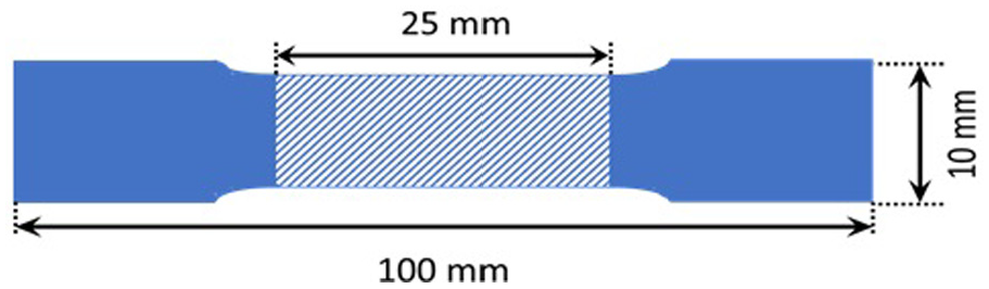
Schematic of the smooth tensile specimen.
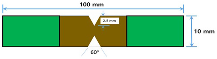
Schematic of the notch tensile specimen.
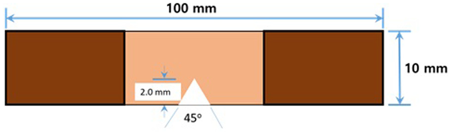
Schematic of the impact testing specimen.
Texture analysis
The crystallographic texture of all the weldments was analyzed using electron backscatter diffraction (EBSD), through a setup attached to the scanning electron microscopy (SEM), and the effect of texture of FZ on the mechanical properties of the joint are discussed in detail.
Results and discussion
Physical appearance of the weldments
The weldment appears to have a bright silvery appearance for all the three weldments as shown in Figure 9, suggesting no or insignificant contamination of the weldment as indicated by Lathabai et al. 33 A contaminated weldment would lead to a purple and bluish appearance as reported by Li et al. 34 However, certain parts were probably contaminated as they appeared blue in color. The bright silvery appearance shows better quality of welds.
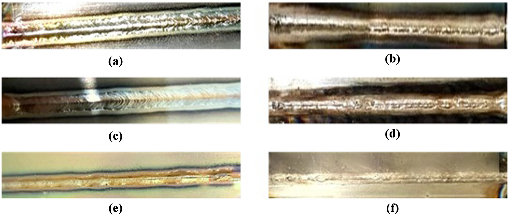
(a) Rectangular pattern, top surface; (b) rectangular pattern, bottom surface; (c) triangular pattern, top surface; (d) triangular pattern, bottom surface; (e) non-oscillated weldment, top surface; and (f) non-oscillated beam weldment, bottom surface.
Figure 10 shows the macrographs of the cross section of weld pool obtained for rectangular, triangular patterns and non-oscillated beam weldment, and it appears that the weld pool depth in all weldments extended to full sheet thickness. The non-oscillating patterns are characterized by low heat input owing to the shortest path which it takes while moving along the weldline as compared to other welding patterns. 7 The relative weld pool width of all the weldments is shown in Table 3. Owing to this reduced heat input, the non-oscillating pattern has a reduced size of the weldment (both top and bottom width) as compared to the triangular pattern and rectangular pattern. As the welding speed was kept same for all the weldments, therefore the heat input was the sole parameter to affect the weld pool width in all weldments.
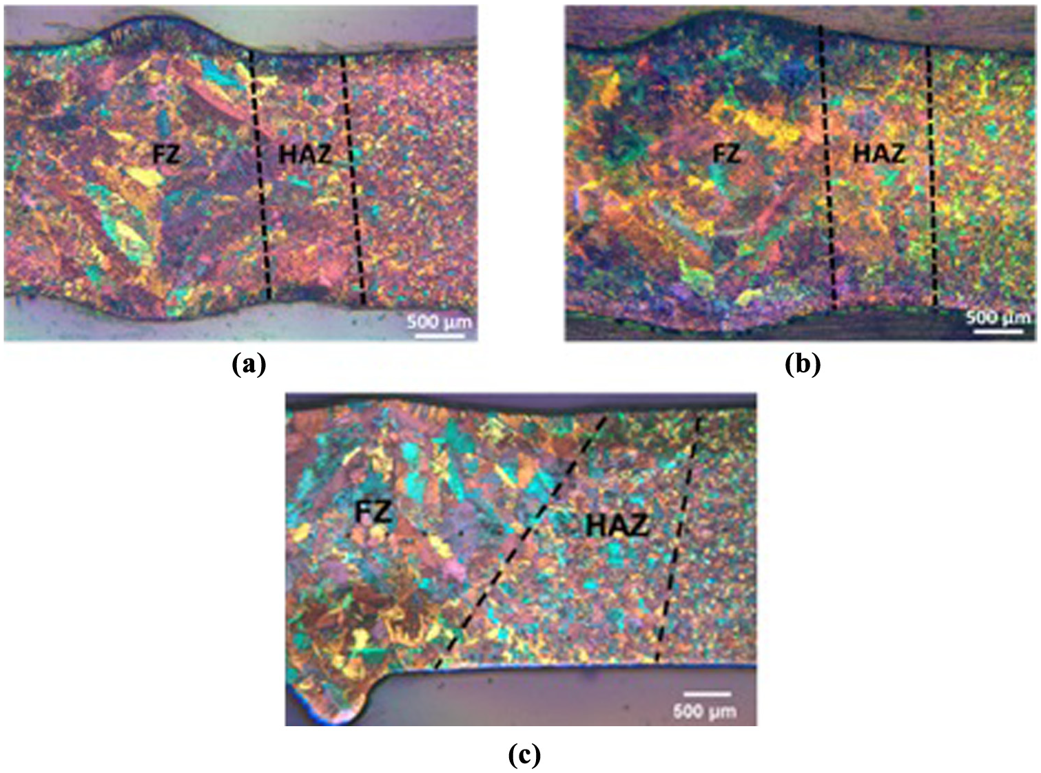
Cross section of variation in weld pool: (a) rectangular pattern; (b) triangular pattern; and (c) non-oscillated weldment. 1
Variation in weld pool.
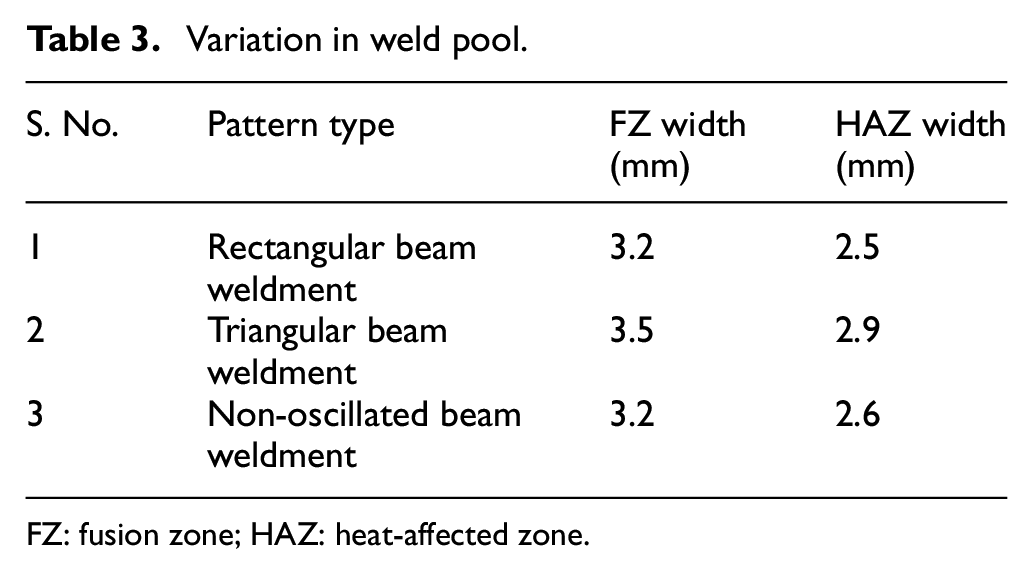
FZ: fusion zone; HAZ: heat-affected zone.
Microstructural characterization
Optical microstructure of BM
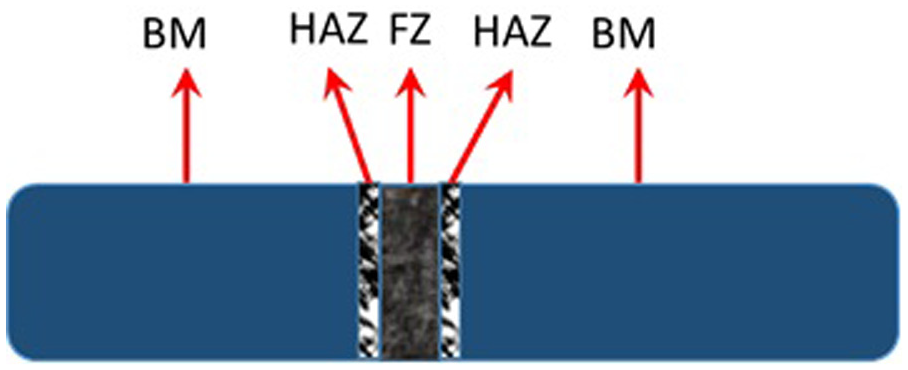
Figure 11 shows the optical microstructure of Ti-5Al-2.5Sn BM, which clearly shows the presence of primary α grains, with β grains at the grain boundaries. Figure 11 shows the microstructural variation from BM to FZ of triangular and rectangular pattern. Since the microstructure in FZ and HAZ is mainly composed of acicular α, columnar α and α′ martensite, hence the FZ and HAZ grains have hexagonal closed pack (HCP) crystal structure, while grain boundaries have body-centered cubic (BCC) crystal structure.
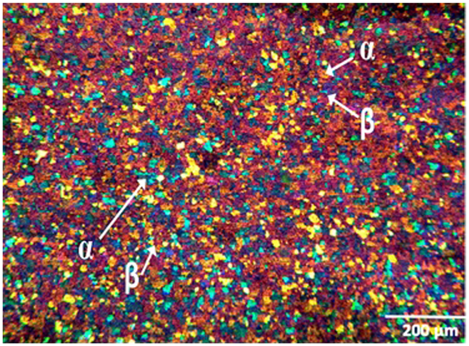
Base metal (Ti-5Al-2.5Sn).
Microstructure of welds
In EBW, the power density is high which means that it requires less heat input which leads to higher cooling rates.1,35,36 If the cooling rate exceeds 410 °C/s, the prior β grain boundary will completely transform into acicular α, and α′ martensite.1,37 Figure 12 shows the FZ of non-oscillated EB weldment. However, it is evident from Figure 13, where the presence of grain boundaries suggested, that completely martensitic structure was not formed in any of the oscillation beam weldments. It is also evident from Figure 13 that the β grain size increased in both patterns from BM to HAZ. This increase in β grain size took place due to retention of heat near the grain boundary during solidification of weld pool. This can also be attributed to the low conductivity of titanium and its alloys which increased β grain size.
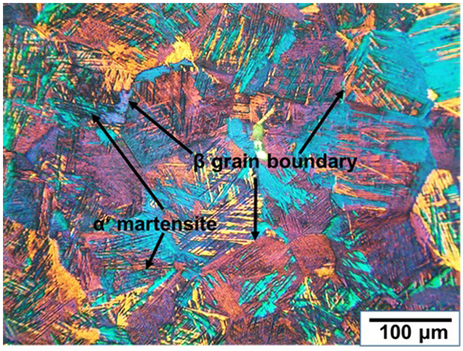
FZ of non-oscillated EB weldment. 1
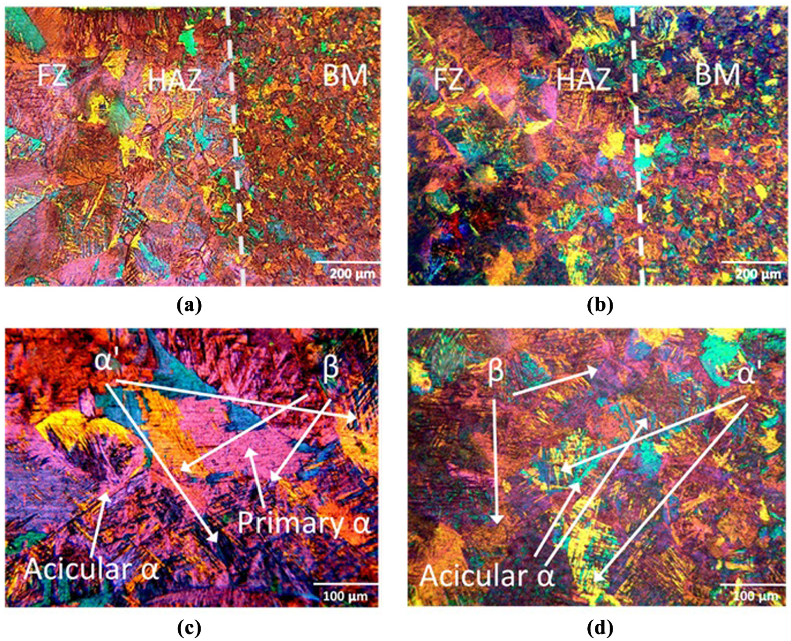
(a) Overview of the rectangular pattern; (b) overview of the triangular pattern; (c) FZ of rectangular pattern; and (d) FZ of triangular pattern.
In beam oscillation mode of EBW, in order to melt the same alloy, there is a higher degree of heat input as compared to the non-oscillation mode. This significantly reduces the cooling rate resulting in coarse martensitic grains and increased β grain size in the FZ of weldments obtained with beam oscillation.1,37 From Figures 12 and 13, it can be observed that the FZ of triangular pattern has relatively wider α lath whereas in the rectangular patterns, the α lath width has decreased. The α lathe appears to be finest and nearly needle like in the FZ of non-oscillated weldment. This difference in microstructure is suggestive of a low cooling rate and therefore a higher heat input per unit area of the weld region in triangular beam oscillation. 38
Micro-hardness
The micro-hardness variation across the weldment from the BM to FZ is due to change in phase and grain size.1,39 The micro-hardness profile of both EB patterns with beam oscillation and weldment from non-oscillating beam from our previous study 1 is presented in Figure 14 in order, to elaborate the effect of different beam oscillations. It is clear from the measured values that the hardness increased in both welding patterns and the highest values were observed in FZ. The high values in FZ is owing to the presence of acicular α and α′ martensite which contribute to increase in hardness. It has also been mentioned that the formation α′ martensite is dependent upon cooling rate of weld pool during solidification.1,7 The hardness profile shows that the average Vickers hardness of welding rectangular pattern was more than triangular pattern as shown in Table 4. This suggested that the proportion of acicular α and α′ martensite (harder phase) formed in rectangular pattern was higher than triangular pattern. The formation of acicular α and α′ martensite is related to cooling rate, and since cooling rate was higher in rectangular pattern due to its welding pattern shape, more acicular α and α′ martensite formed in rectangular pattern than triangular pattern which increased the hardness of rectangular pattern. The non-oscillated EB beam weldment has greater hardness than both oscillated EB patterns due to greater cooling rate than the oscillated beam, which led to more martensite being formed in non-oscillated beam weldment. Previously, it has been reported and it is also evident from present study that hardness of phases is in the order α′ martensite > acicular α > β. 40 Table 4 makes it clear that the average hardness value in FZ and HAZ in the weldments produced when using rectangular beam oscillation is higher as compared to weldments produced by triangular beam oscillations. These results are consistent with the microstructural analysis discussed in section “Optical microstructure of BM.”
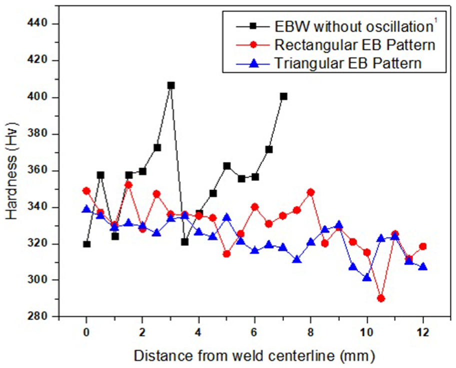
Micro-hardness profile of the EBW weldments with and without oscillations.
Average hardness values.
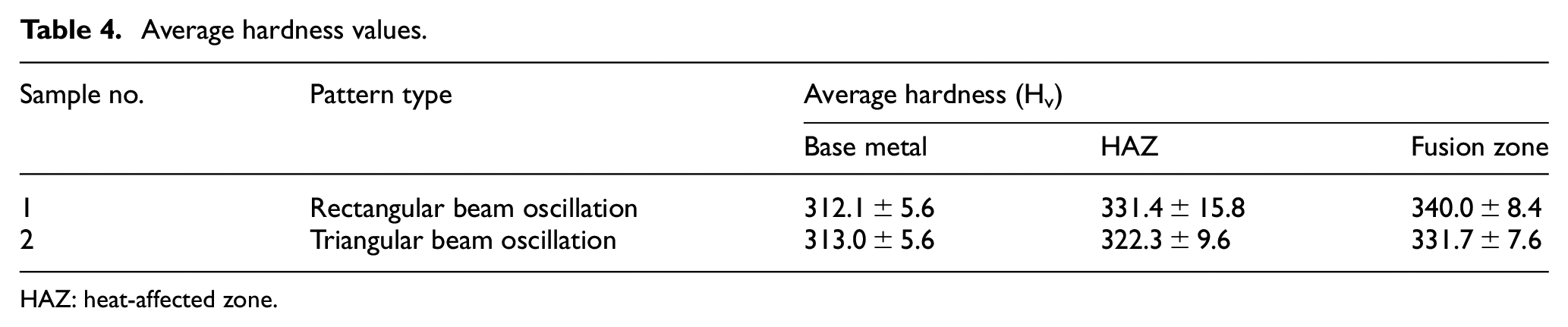
HAZ: heat-affected zone.
Mechanical properties
Figures 15 and 16 show the stress–strain relations for smooth and double-notch tensile tests of the samples produced by the rectangular and triangular beam oscillations and non-oscillated beam. The result shows that the both patterns of EBW show similar trend in terms of strength and elongation. The fracture of triangular weldment was relatively more ductile than rectangular weldment as shown in Figure 15. Smooth tensile sample of both welding patterns also fractured from BM, indicating the high strength of weldment in EBW. Figures 17 and 18 show the SEM images of fractured weldments of EB patterns with beam oscillation, while Figure 19 shows the SEM images of non-oscillated EB weldment. It can be seen that both welded patterns exhibited fibrous fractured surface with dimples, suggesting brittle fracture mode. It is also clear from SEM images at higher magnifications that the triangular beam pattern has deeper and smaller dimples as compared to rectangular beam pattern. These smaller dimples enhanced the ductility in triangular pattern which increased the elongation in triangular pattern than the rectangular pattern and non-oscillated weldment. The non-oscillated weldment as shown in Figure 19 has fine dimples and higher porosity than oscillated EB patterns which decreases the ductility of non-oscillated EB weldment. These results are consistent with the results presented in the sections “Microstructural characterization” and “Micro-hardness.”
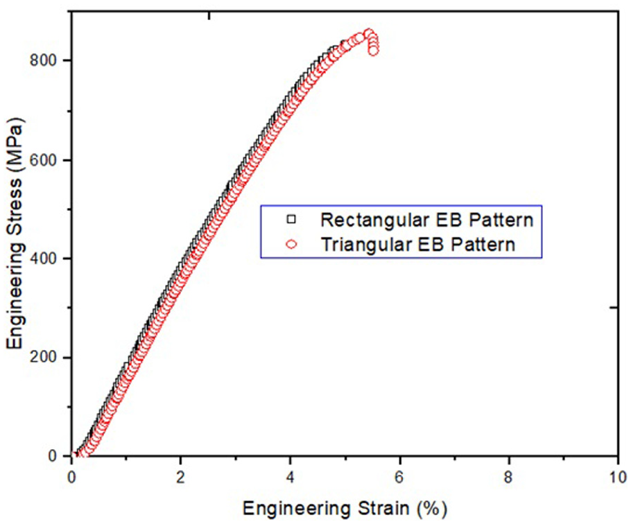
Tensile test result of double-notch samples.
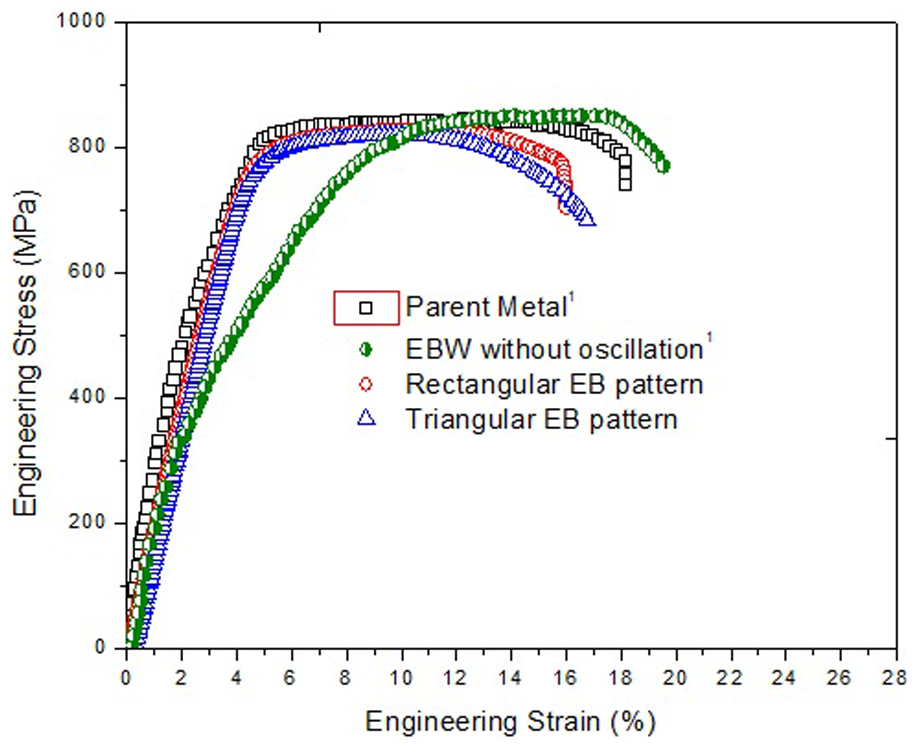
Tensile test result of smooth samples of the EBW weldments obtained with and without oscillations.
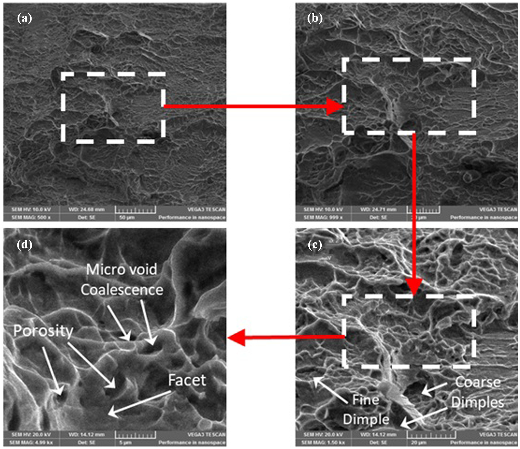
SEM images of fractured surface rectangular pattern weldment.
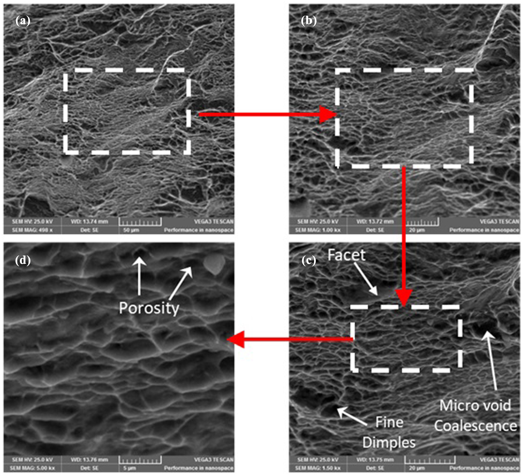
SEM images of fractured surface of triangular pattern weldment.
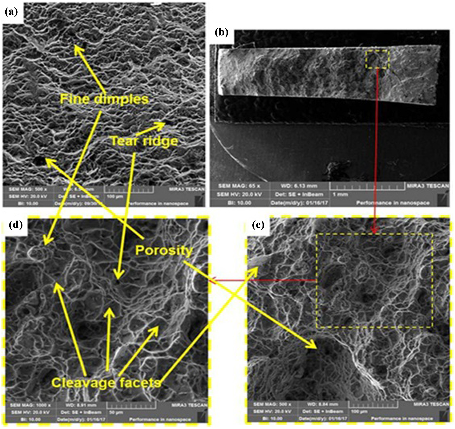
SEM micrographs of the fractured surfaces of (a) BM specimen and (b)–(d) EBW specimen without oscillation. 1
Texture analysis
Although most literature suggests that tensile strength decreases as the average grain size increases, but these observations were based on samples with no defects and without the presence of notch. However, in the presence of a notch, the coarse microstructure is beneficial, as the average grain size increases the ductility hence more toughness and less notch sensitivity. Therefore, in the presence of a notch, as was in this case, coarse microstructure was favorable and explained the increase in notch tensile strength (NTS) (Figure 20). However, apart from the grain size, the texture of the FZ also affects the mechanical properties and is discussed further in the following section.
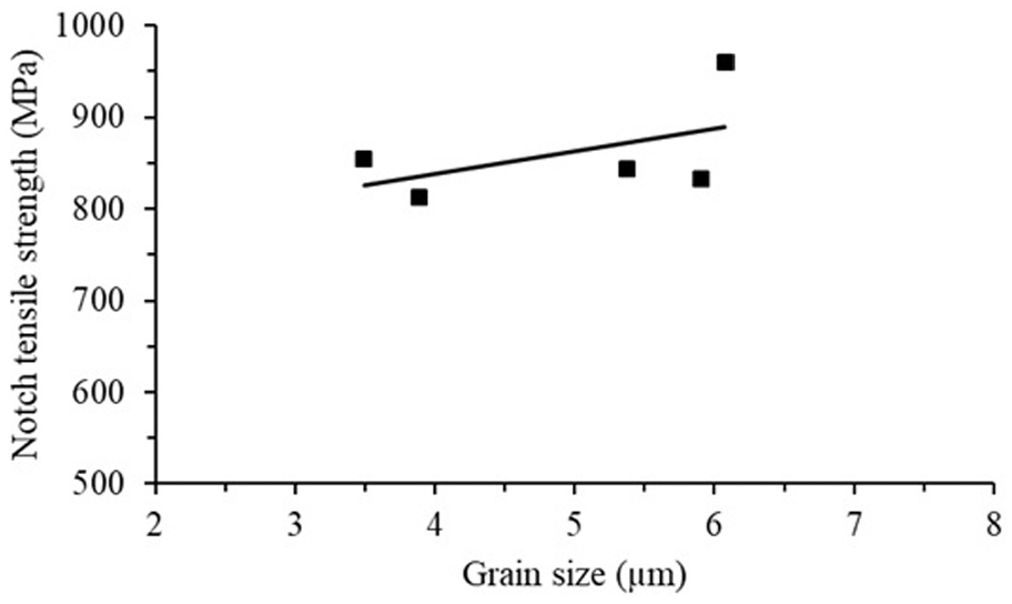
Effect of grain size on notch tensile strength.
The observed fine α lathe in triangular pattern is suggestive of an increased hardness and strength according to Banerjee and Williams.
38
However, it can be observed that there is no significant difference in the mechanical properties of triangular and rectangular patterns. The observed increase in micro-hardness of rectangular pattern showed that an increase in α lathe width is not significantly degrading the mechanical properties of rectangular patterns. This may be attributed to the texture strengthening due to weld pool stirring in the rectangular pattern. For further investigation, EBSD analysis was performed on all the three weldments. Figure 21(a)–(c) shows the EBSD results of FZ with different welding strategies. It was noted that there was a considerable difference in texture in the FZ of these samples. The intensity distributions of the {0001}, {11-20} and {10-10} pole figures of the α-phase are shown in Figure 22 for rectangular EB pattern and triangular EB pattern. Rectangular EB pattern showed strong texture of basal plane (0001) and prismatic plane (01-10), which is parallel to the rolling direction while in triangular EB pattern the basal texture is not significantly pronounced in rolling direction, while prismatic (12-30) and pyramidal planes (01-10) texture can be seen (Figure 22). These different orientations indicate different slip mechanism under tensile loading, which is dependent on grain orientation, with respect to the applied load and is represented by Schmid factor (m) and critical resolve shear stress value of that slip system. The most dominant slip systems in alpha titanium is pyramidal
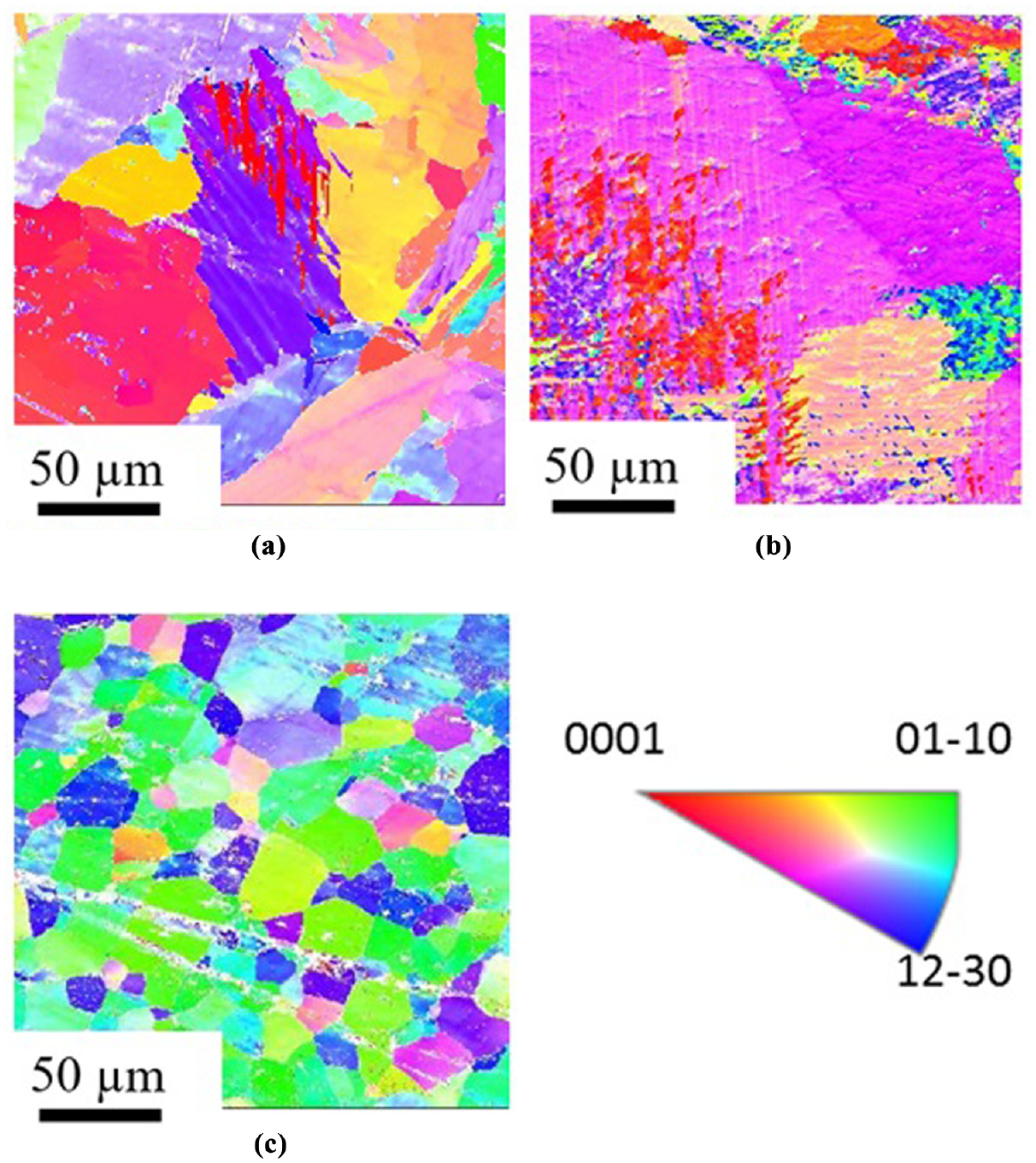
EBSD color mapping of (a) FZ of rectangular pattern; (b) FZ of triangular pattern; and (c) base metal.
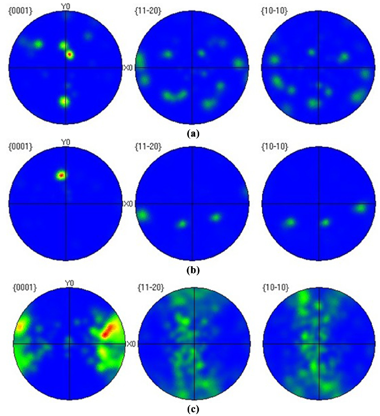
Pole figures of alpha phase: (a) FZ of rectangular EB pattern; (b) FZ of triangular EB pattern; and (c) base metal.
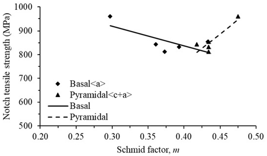
Graph of Schmid factor versus notch tensile strength of fusion zone of different welding strategies.
Impact test
Charpy test was also performed on the samples produced by the two different beam oscillations, in order to measure the impact toughness. The results are presented in Table 5, which show that triangular beam pattern has higher impact strength than rectangular beam pattern. The increase in notch toughness in the triangular beam pattern compared to rectangular beam pattern can be correlated with the microstructure of weld pool of triangular pattern which is more uniform and well dispersed. The uniform microstructure led to increase in the tri-axial stress state which hinders stress cavitation for failure and therefore triangular beam pattern had higher notch toughness as compared to rectangular beam pattern.43,44
Charpy test result.
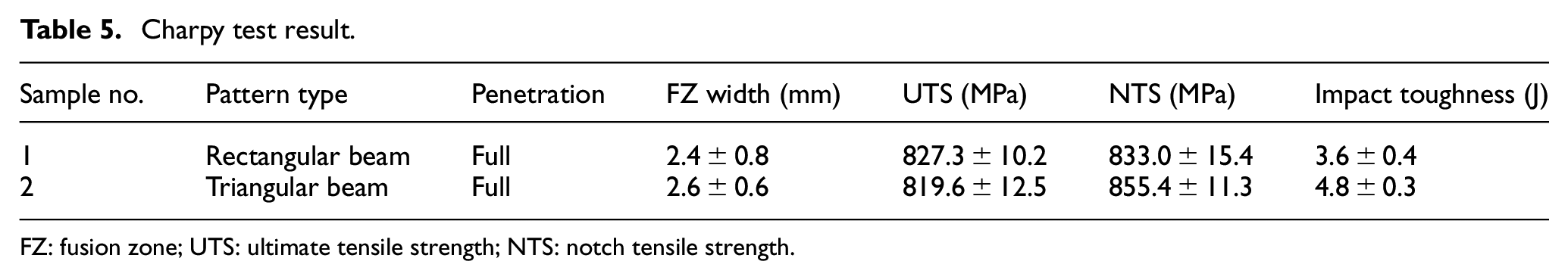
FZ: fusion zone; UTS: ultimate tensile strength; NTS: notch tensile strength.
Residual stresses
Residual stresses in weldment are a combination of volumetric variations due to phase changes and non-uniform thermal strains. The residual stresses in weldment were measured using Hole-drill method. Figure 24 shows that the stress profile is non-uniform in both patterns, because the normalized strains are not in the shaded region, according to the methodology explained by Niku-Lari et al. 45 to calculate residual stresses. In this method, the normalized coefficients “P” and “Q” can be calculated using relieved strain data points. Figure 24 shows solid line of “P” and “Q” strains, and they show a standard case of uniform stress profile. If the strain data points “P” and “Q” lie in the area between solid lines, then it means uniform through thickness stress profile. Owing to the non-uniformity in stress profile, integral method was used to calculate residual stresses using normalized strains which is explained in great detail by Grant et al. 46 The transverse and longitudinal stresses were measured and are presented in Table 6, and clearly show that rectangular beam pattern had higher residual stresses as compared to triangular beam pattern. This was attributed to overall higher heat input and less cooling rate in rectangular patterns.
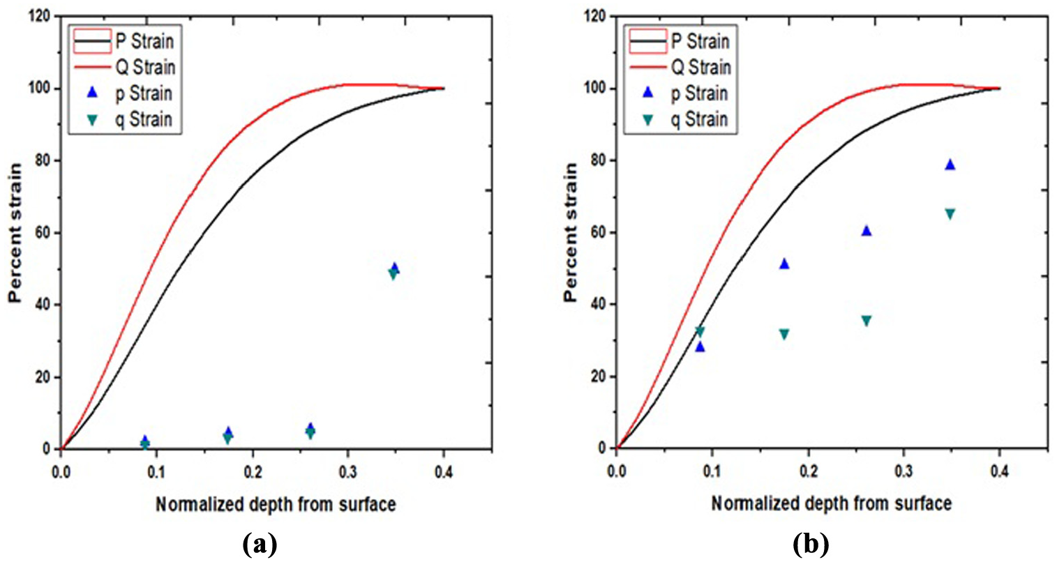
Percentage of residual strains as a function of normalized hole depth: (a) rectangular pattern; (b) triangular pattern.
Residual stresses in EB patterns.
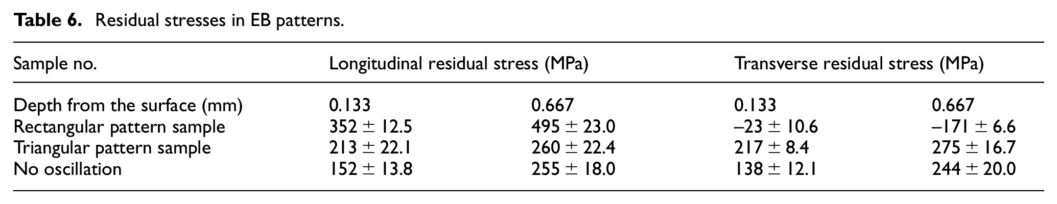
The magnitude and direction of residual stresses give important information about the processing carried out on the alloy. The main factors are plastic flow, differential cooling rates and phase transformations. During the welding process, molten material cools instantly due which the weld line region experiences rapid contractions; however, as it is connected with the parent metal, there is a state of tensile residual stresses developed at the weld line (longitudinal direction). 47 An increased heat input during the welding process intensifies this phenomenon and further enhances the state of tensile residual stress in the longitudinal direction. 48 In the case of titanium alloys, fast cooling after welding leads to the formation of α′ martensite and acicular α from β phase during which the local volume of the material increases, owing to size difference between HCP and BCC crystals. This induces compressive residual stresses in the region 49 and reduces the intensity of tensile residual stresses generated due to rapid weld pool contraction. As discussed earlier, the oscillating patterns are characterized by a low heat input owing to the path which it takes while moving along the weldline as compared to non-oscillating pattern. As shown in Table 6, this resulted in a significant increase in residual stresses in both longitudinal and transverse direction in the weldments obtained using oscillating patterns.
Conclusion
EBW was performed using two different types of beam oscillations on Ti-5Al-2.5Sn alloy. The observed microstructure in the FZ of triangular pattern was significantly refined; however, the micro-hardness and mechanical properties were not significantly different than that of the rectangular pattern. Micro-hardness of rectangular pattern was observed to be higher than the triangular pattern, regardless of the wider α lathes in the FZ. Moreover, the tensile strength and elongation was also comparable to the triangular pattern and non-oscillated beam. This was attributed to the observed texture strengthening in the FZ of rectangular pattern due to excessive churning effect. However, residual stresses were observed to be maximum (tensile) in both the oscillating patterns, due to high overall heat input in the welding process as compared to the non-oscillating pattern. Moreover, the impact toughness of triangular pattern was observed to highest due to a strong texture in the prismatic and pyramidal plane of the triangular EB pattern weldments.
Footnotes
Data availability
The raw/processed data required to reproduce these findings cannot be shared at this time as the data also form part of an ongoing study.
Declaration of conflicting interests
The author(s) declared no potential conflicts of interest with respect to the research, authorship, and/or publication of this article.
Funding
The author(s) disclosed receipt of the following financial support for the research, authorship, and/or publication of this article: The authors wish to acknowledge GIK Institute for financial support.