
Abstract
Metal matrix composite is made of non-metallic reinforcements (usually ceramic) in metal matrices that are widely used in various industries, including aerospace and automotive. Two main components of metal matrix composite are the matrix (base metal) and the reinforcing particles that tend to increase the hardness of the workpart. The production and machining of such materials are hard and costly. However, due to their excellent mechanical properties such as high strength to weight ratio, high hardness and rigidity, corrosion resistance, abrasion resistance, and low thermal coefficient, their applications are still growing in various aspects. One major division of metal matrix composite is aluminum metal matrix composite with ceramics particulate reinforcement such as silicon carbide and alumina. According to review of literature, a low volume of information was found in terms of machinability of specific grades of aluminum composite (A356-10% silicon carbide) under various lubrication modes. Therefore, in the course of this study, several blocks of aluminum metal matrix composite (A356) reinforced with 10% silicon carbide elements were used under dry, minimum quantity lubrication and wet milling operation. The maximum flank wear, tool wear modes, as well as the average surface roughness were recorded and were subsequently studied as the machining performance attributes. The use of lubricants in both minimum quantity lubrication and wet modes led to reduced tool wear as compared with readings made under dry mode. However, under similar experimental conditions, no significant improvement was observed on the average surface roughness values.
Introduction
Metal matrix composite (MMC) is referred to as the category of engineering materials with growing applications in the automotive and aerospace industries. Examples of MMC applications include engine parts, brake system, driveshaft, and others such as pump housing and supercharger compressors. 1 The advantage of MMC over industrial metals is the possibility of modifying material properties by combining matrix alloys and the reinforcement phase. The reinforcement phase in MMC can be presented in the form of particulate, short fiber and whisker, continuous fiber, and monofilament. One major division of MMC is aluminum alloy matrix composite (Al-MMC) with ceramics reinforcements such as silicon carbide (SiC) and alumina. The ceramic reinforcement has a higher hardness than conventional tool materials, for instance, 2400 Hv of SiC vs 1800 Hv of tungsten carbide (WC). 2 Particulate reinforced Al-metal matrix composite (PRAlMMC) is one of the crucial composites among the metal matrix composites, which have SiC particles with aluminum matrix that is harder than tungsten carbide (WC) and pose several severe difficulties in machining operations. The aluminum alloy reinforced with discontinuous ceramic reinforcements is about to replace with conventional materials in various automotive, aerospace, medical, and automobile industries. 3 However, machining Al/SiC-MMCs is one of the major complications which hinders its widespread applications. 4 The presence of hard ceramic particles led to significant difficulties in machining operations and rapid tool wear. Although many works are currently in progress to decrease the needs for machining operations by proposing subsequent manufacturing operations such as near net shape forming and modified casting, machining is still an integral part of the manufacturing chain. The final surface quality and tolerance are critical elements for a wide range of components. The most reliable method to acquire desired levels of quality, as aforementioned, is machining.5–8 This is especially true in the case of MMCs, which are generally hard to cut materials. 9 Research works into improving or quantifying the machinability of MMCs that has been undertaken since the early 1970s.10–13 This is especially useful since carbide inserts are cheaper, and tool wear starts relatively quickly, allowing the evaluation of different parameters in order to determine their machinability and suitability for critical conditions. This is also ideal for evaluating the effects of cooling methods under similar conditions. The conducted research studies revealed that carbide tools were used in over 53% of cutting tests. According to the review of literature, coated or uncoated carbide inserts were not often used. As noted by Barnes and Pashby, 14 Durante et al., 15 and Tomac et al., 16 high-speed steel (HSS) and ceramic tools are both unsuitable for machining MMCs. Investigations into the effects of cutting speed on abrasive flank wear have shown that minimum wear is achieved by optimized cutting speed.17,18 The study by Pandi and Muthusamy 19 revealed that decreased average surface roughness (Ra) could be improved at medium cutting speeds. Many studies have suggested that reduced cutting speeds tend to generate less diffusion wear during machining MMC.20,21 Diffusion wear becomes an issue as the tool material softens during machining operations with high levels of generated temperature. 22 It has been shown that high cutting speeds are primarily responsible for the softening of the tooltip due to generated temperatures at high speeds. 23
The conducted research studies about the use of lubricants while machining MMCs have been the source of attention in recent years, and daily attempts to discover solutions to overcome machinability concerns of MMCs and many other hard to cut materials are in progress. As noted by Gururaja et al., 24 the use of cutting fluid could be redundant due to the lack of improvement in the performance of machining operations under cooling operation. Dry machining generally generates high temperatures over the use of coolant, leading to built-up edge (BUE). The increased temperature also increases the risk of wear by diffusion, which occurs when atoms from the reinforcement matrix and the tooltip are exchanged, resulting in a weakened tooltip and the associated negative impact on the cutting tool’s properties. 25 Higher machining temperature led to an exponential increase in the rate of diffusion wear. 26 The use of traditional coolants while machining MMCs was investigated by Hung et al. 27 It was exhibited that the use of cutting fluid would neither increase nor decrease the cutting tool life. It was also found that the use of flood machining had no effects on machinability improvement under low cutting speeds. However, smaller cutting forces were observed at higher cutting speeds. 23 Solhjoei et al. performed high-speed milling tests with carbide tools on alumina-reinforced aluminum of varying reinforcement particle concentrations. It was found that the use of minimum quantity lubrication (MQL) may lead to satisfactory surface finish and tool wear when machining 10% and 15% alumina-reinforced MMC. The same study revealed that MQL was not appropriate for 20% reinforced MMC, and high flank wear was observed. 28
Knowing that aluminum matrix reinforced with SiC reinforcing particles are the most commonly used MMCs, research studies into improving their machinability is of prime importance. A review of literature denotes that milling aluminum metal matrix composites-grade (A356)-reinforced with SiC elements under various lubrication modes was not reported in the open literature. To better draw an operational window for improving part quality while maintaining the machining time and costs within an appropriate level of precision and quality, the main machinability attributes, including cutting forces, the surface roughness Ra, as well as tool wear modes, were studied in dry, wet, and MQL milling of A356-reinforced with 10% SiC. The effects of cutting parameters aforementioned on maximum flank wear, tool wear modes, as well as Ra were studied. Comprehensive material characterization was also conducted in the course of this work to evaluate the tool wear modes under various cutting conditions.
Experimental procedure
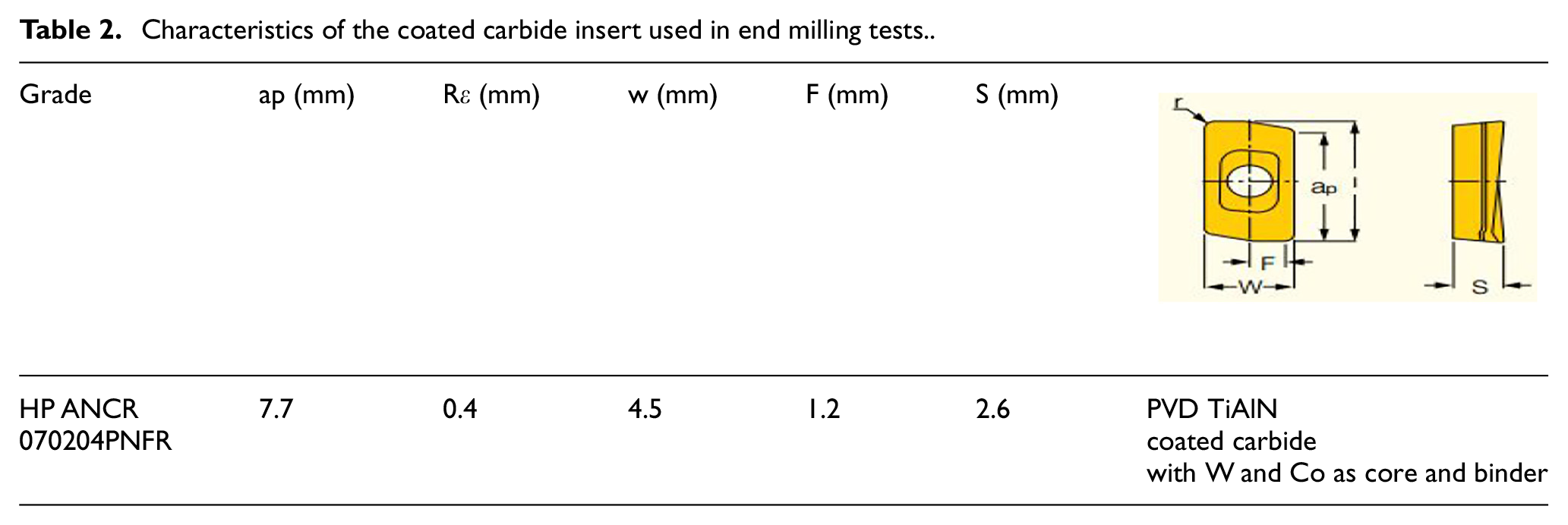
The cubic blocks of A356 with 10% volume fraction of SiC particles with uneven shapes and 10–20 μm size with dimensions 21.68 × 12.05 cm were used in the end milling tests. The cutting operations were performed on a three-axis computer numerical control (CNC) machine tool (power: 50 kW, speed: 28,000 rpm; torque: 50 Nm) under different lubrication conditions, including dry, MQL, and wet. According to Table 1, the cutting speeds of 120, 180, and 240 m/min, depth of cut 1 mm, and feed rate 0.1 mm/tooth were used. The experimental setup is shown in Figure 1. The Iscar coated carbide insert was used in the tests (Table 2). The bio-lubricant MecGreen was used in MQL and wet tests under flow rates of 150 mL/h for MQL mode and 5 L/h for the wet mode. The cutting tests were repeated twice, and the average values of readings were used in the course of result analysis. The surface roughness measurement was conducted on the profilometer Mitutoyo SJ 400. To better elaborate the effect of cutting parameters and tool wear mode on the surface quality, the surface roughness measurement was conducted within the entrance, center, and exit sides of the workpart in each sample, and an individual set of analyses was performed concerning each section presented in Figure 2.
Machining parameters used.
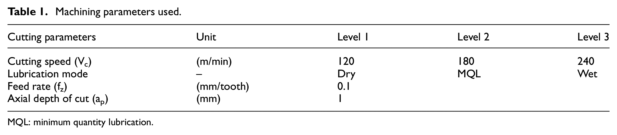
MQL: minimum quantity lubrication.
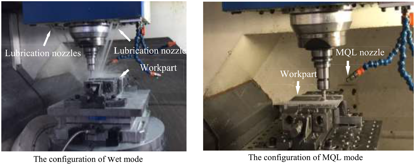
Overview of the experimental setup.
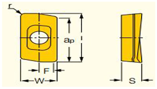
Characteristics of the coated carbide insert used in end milling tests.
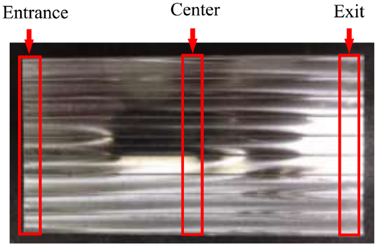
Overview of surface roughness measurement approach.
Methodology
Upon completing the milling tests, the scanning electron microscope (SEM) images were captured from both rake, and flank faces, followed by energy-dispersive X-ray spectroscopy (EDS) analysis, examining the material components remained in the machined part and cutting tool surfaces. The wear rate and morphology, as well as the Ra readings, were evaluated under different cutting conditions.
Results and discussion
Tool wear morphology at dry mode
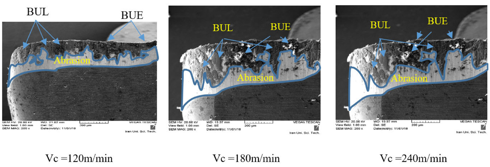
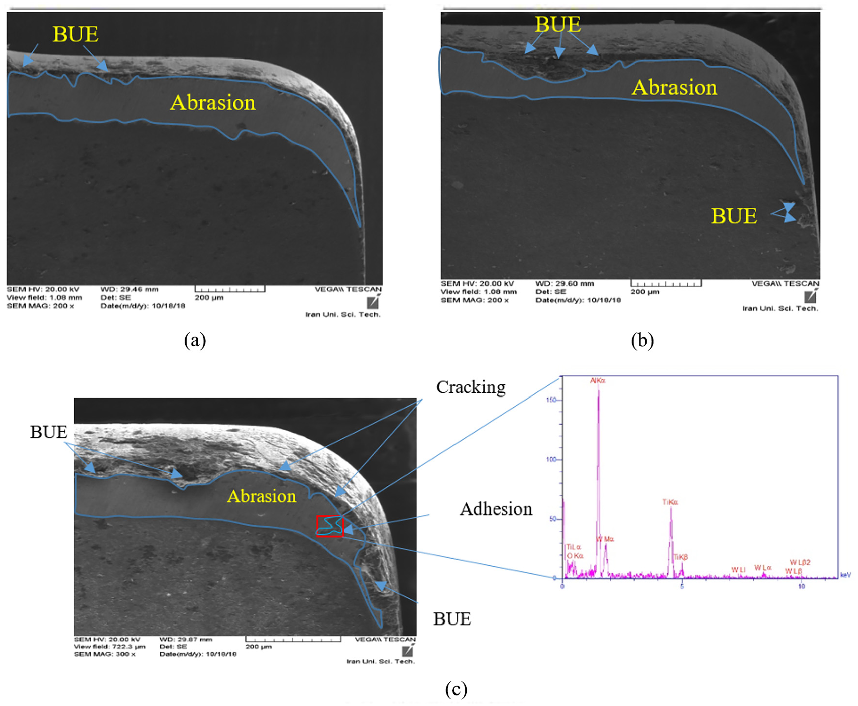
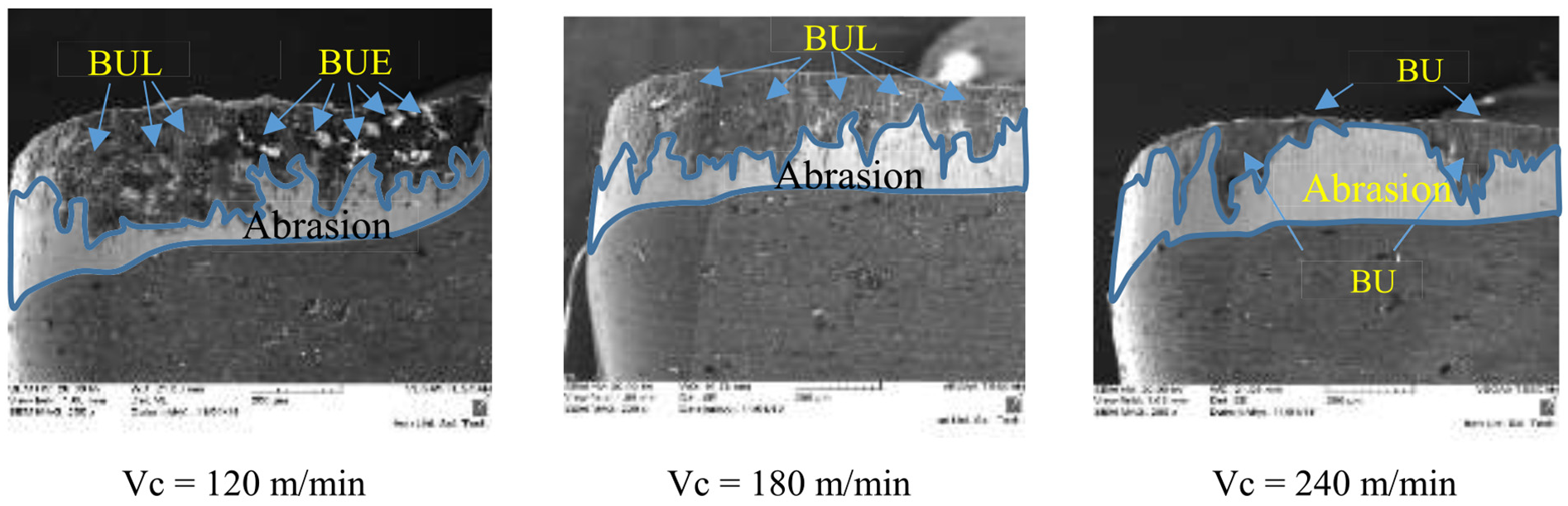
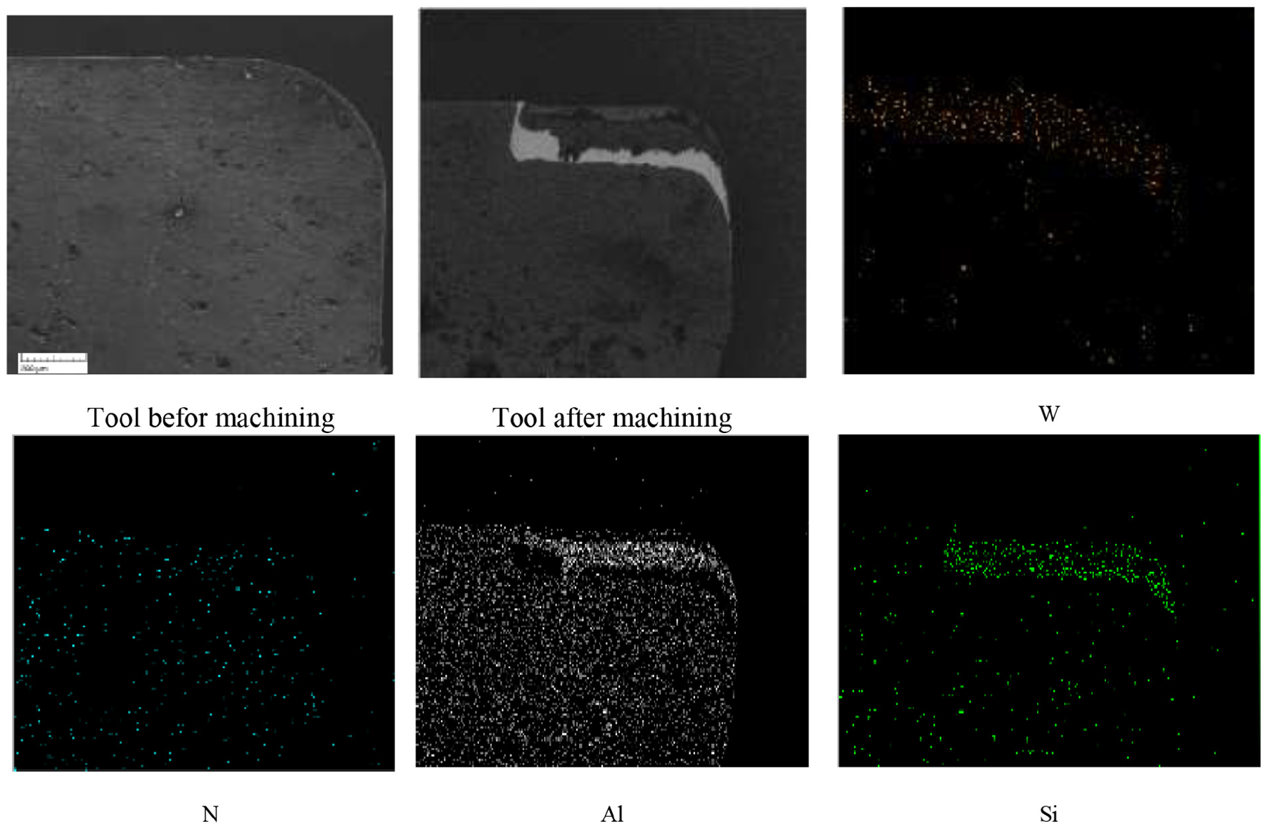
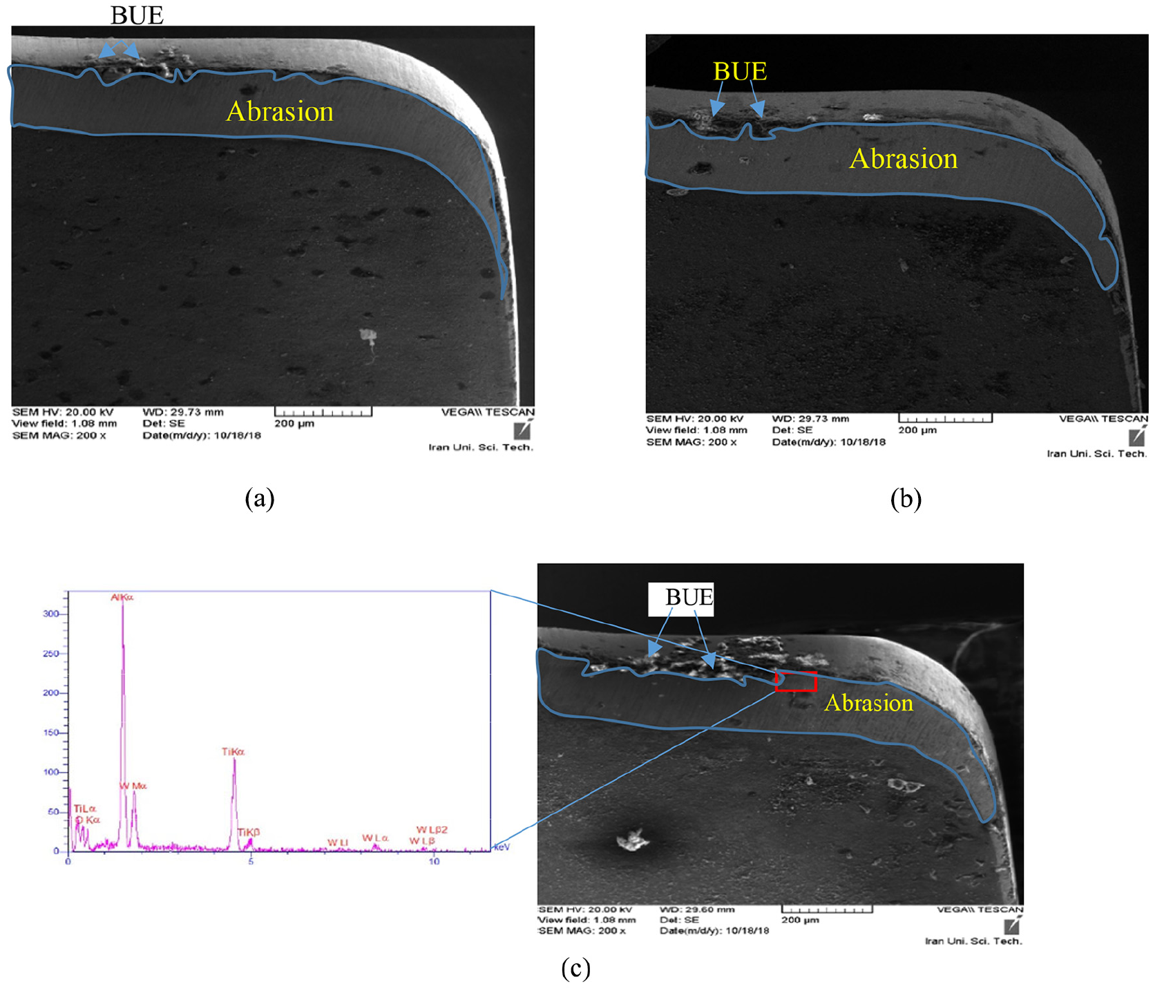
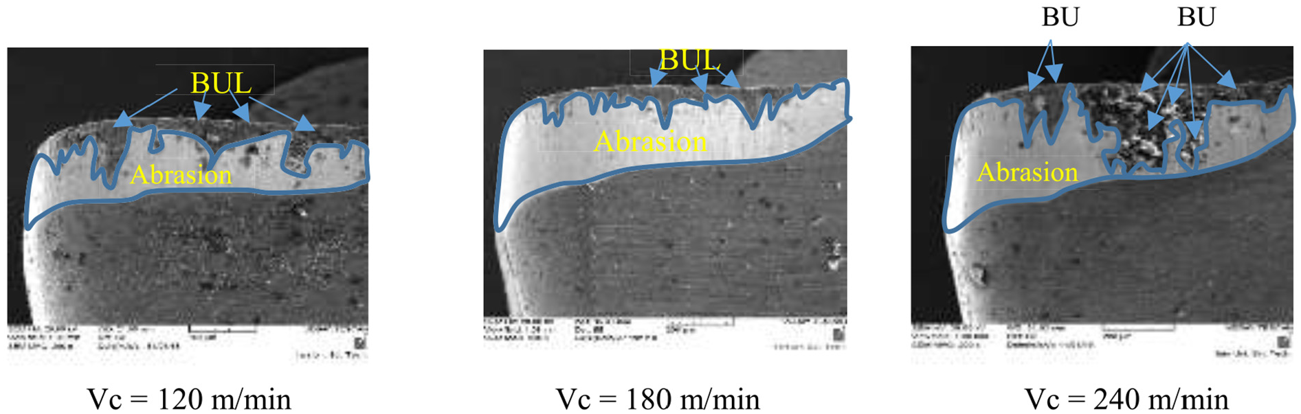
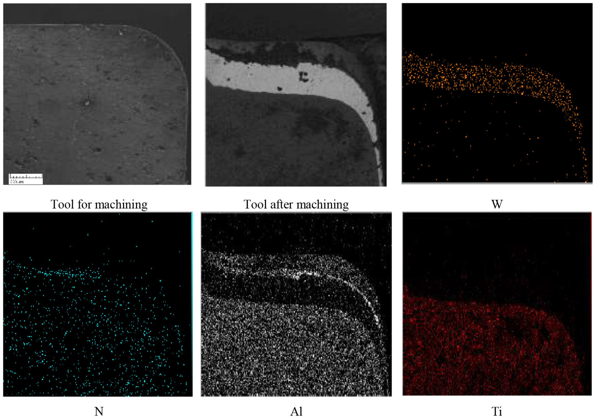
To better elaborate the differences between the worn and unworn inserts, the flank face of the unused insert is shown in Figure 3. According to SEM images in Figure 4, it can be indicated that despite the level of cutting speed used, the abrasion mode exists in the cutting tool surface. The mapping analysis of the rake face (Figure 5(a) and (b)) shows that the amount of titanium, nitrogen, and aluminum elements, which are the main elements of coating are significantly reduced in the tool’s cutting edge. In contrast, the amount of tungsten in this area was increased. Knowing that tungsten is the core element of the cutting tool, its presence indicates the abrasion wear, where the coating has been removed. The abrasion is the dominant wear mechanism that may occur due to the interaction between SiC particles in the workpart and the tool. SiC particles act very similar to cutting edges. According to Manna and Bhattacharyya, 29 the leading cause of tool wear in machining MMCs is due to the collision of SiC particles with the surface of the carbide tool. Another important phenomenon that has been identified from SEM images is the formation of a BUE at the cutting tool edge. At cutting speed 120 m/min, less BUE was observed as compared with those found under higher cutting speeds used (Figure 6). It can be expressed that the utilized cutting speed is close to the critical cutting speed that tends to generate BUE. The cutting tool used under cutting speed 240 m/min was exposed to more abrasion, BUE, and built-up layer (BUL). According to Figure 4(c), the presence of more aluminum on the cutting edge can be correlated to BUE in that area. At a higher level of cutting speed, the wear rate is increased, where it has no significant effects on the BUE phenomenon. Due to the lack of cutting fluid and also the non-homogeneity of the reinforcing particles in the matrix, those conditions that may tend to intensify BUE have been provided. Therefore, as clearly shown in Figure 4, the BUE can be observed on the primary and secondary edges of the cutting tool. According to Figure 6, BUE and BUL were also seen on the flank faces of the insert. In the absence of cutting fluid, the use of the higher level of cutting speed (240 m/min) led to diffusion and oxidation phenomenon (Figure 6). The cutting temperature in the machining area increases sharply, and the diffusion and oxidation phenomenon occurs. According to the EDS diagram of the examined area, the presence of tungsten indicated the removal of the coating. Furthermore, the presence of oxygen in this region is an indication of oxidation.
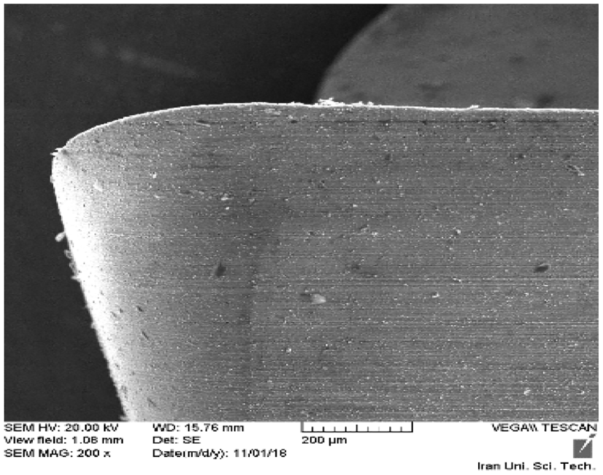
The flank face of unused insert.
SEM images of tool wear on tool rake face in the dry mode.
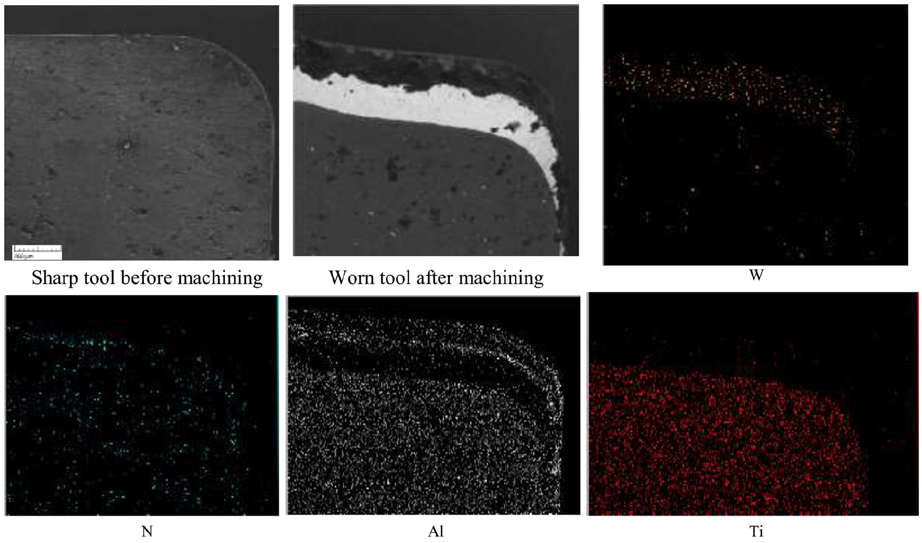
SEM image and EDS mapping analysis of tool rake face in the dry mode.
SEM images of the flank wear under dry mode. (a) Vc = 120 m/min. (b) Vc = 180 m/min. (c) Vc = 240 m/min.
MQL mode
As can be seen in Figure 7, at cutting speed 240 m/min, the BUE is lined up with a piece of workpart on the tool rake face and also on the tool flank wear, which may lead to extended tool life as compared with other two lubrication modes used. The BUE in Figure 7(c) is much smaller than that observed in the dry mode under similar cutting conditions. The presence of a large amount of aluminum on the cutting edge indicates that BUL has been converted to BUE. Also, Figure 8 presented the EDS chart of BUL region, which was occupied with a high level of aluminum. The presence of tungsten on the tool cutting surface as compared with other elements in the mapping analysis (Figure 9), as well as in the EDS diagram indicates the adhesion wear behind the BUL. It can be observed that the use of MQL improves the abrasion mechanism relative to the dry mode and severely reduces the presence of diffusion and adhesion phenomena. The other element that lies in the tool’s flank face is the reduction of the BUE in comparison with dry mode (Figure 8). The use of MQL may tend to reduce the cutting temperature and BUE formation. It is visible that the abrasion on the flank face is less than the observation made under dry mode.
SEM images of wear modes on rake face under MQL mode.
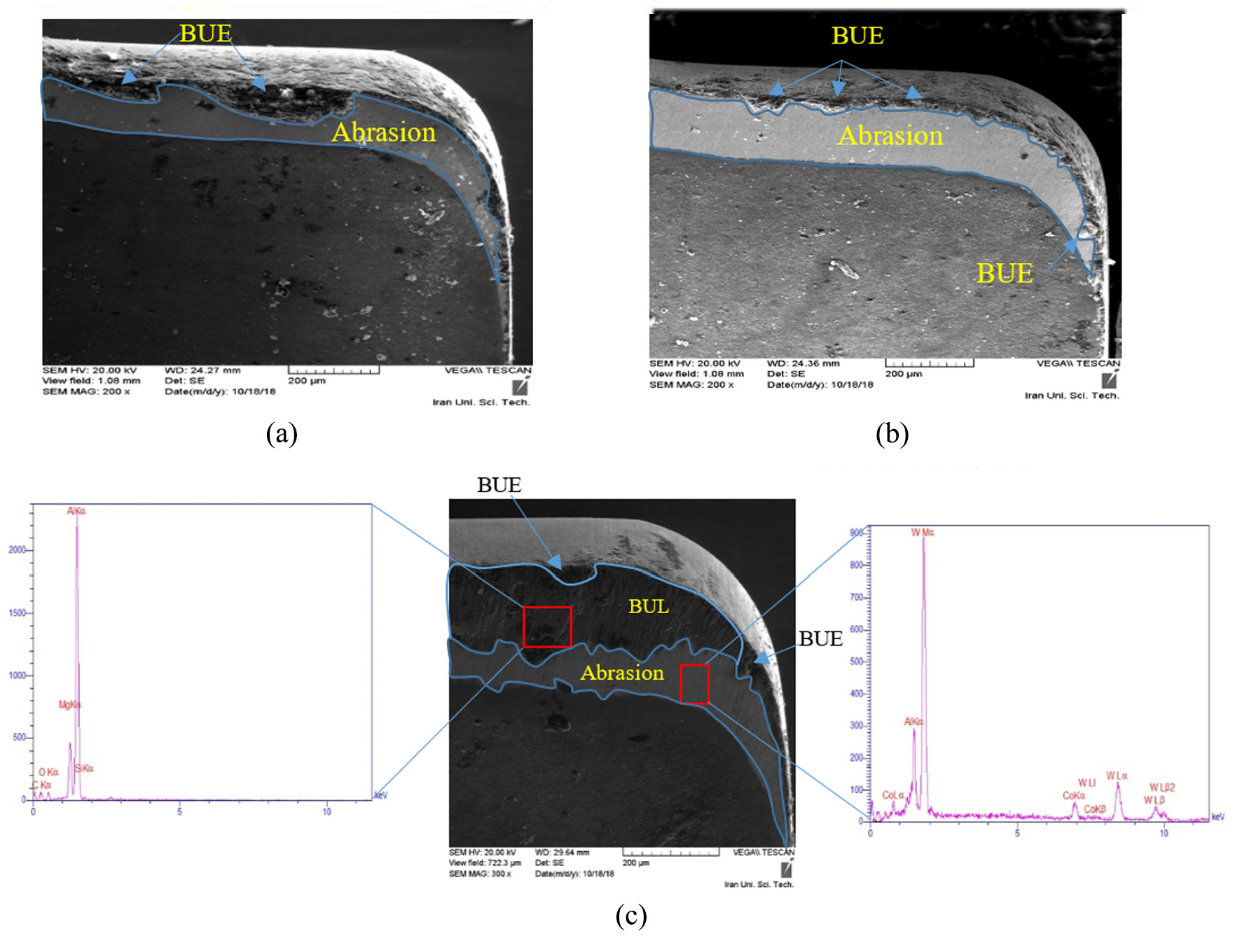
SEM images of wear modes on the tool flank face under MQL mode. (a) Vc = 120 m/min. (b) Vc = 180 m/min.(c) Vc = 240 m/min.
SEM image and EDS mapping analysis of tool rake face in the MQL mode.
Wet mode
According to Figure 10(c), under similar cutting speed, the BUE is much smaller than the ones observed under the other two lubrication modes. However, the abrasion phenomenon still exists. According to Figure 11, the least amount of BUE was found at the cutting speed 180 m/min, and the highest rate was at a cutting speed of 240 m/min. This observation indicates that to reduce the presence of BUE, optimum cutting speed should be used, which is, however, a critical task while nonlinear effects of cutting speed were observed on the BUE under wet mode. This reflects the presence of interaction effects between cutting speed and lubrication mode, which requires additional statistical and experimental studies in this regard.
SEM images of tool wear on tool rake face in the wet mode. (a) Vc = 120 m/min. (b) Vc = 180 m/min. (c) Vc = 240 m/min.
SEM images of tool wear on tool flank face in the wet mode.
Based on the mapping analysis presented in Figure 12, the high percentage of tungsten in the tool cutting area, and the dramatic reduction of aluminum and titanium, which are the coated elements, are an indication of the coating removed from the cutting tool surface. However, knowing that the amount of aluminum on the cutting edges was intensified, it can be stated that the presence of BUE is an inevitable phenomenon in the case of machining such materials. However, lower width and volume of BUE was observed under wet mode as compared with observations made under dry and MQL modes.
SEM image and EDS mapping analysis of tool rake face in the wet mode.
Contrary, less BUE on the flank size was observed under MQL mode. These observations indicate nonlinear interaction effects between lubrication modes and cutting parameters, which tend to complicate wear control and reduction. A systemic approach is then needed to propose simultaneous multiple responses optimization for flank and rake wear control and minimization. It can be generally indicated that the primary wear mechanism observed under wet mode was an abrasion. BUE, which is highly relevant to the cutting temperature in the cutting zone, was less likely found under wet mode than the other two lubrication modes.
Flank wear
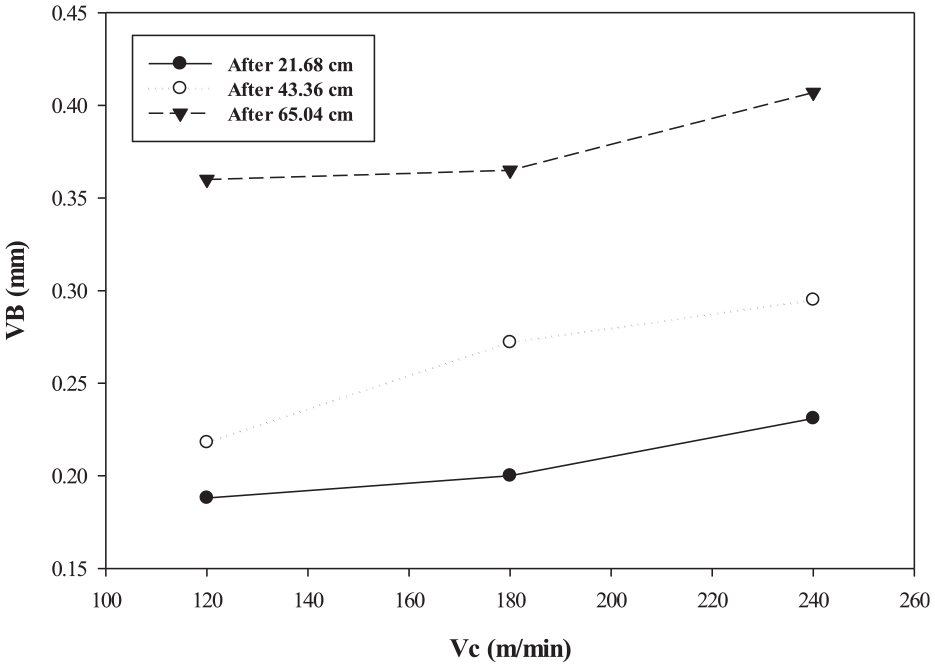
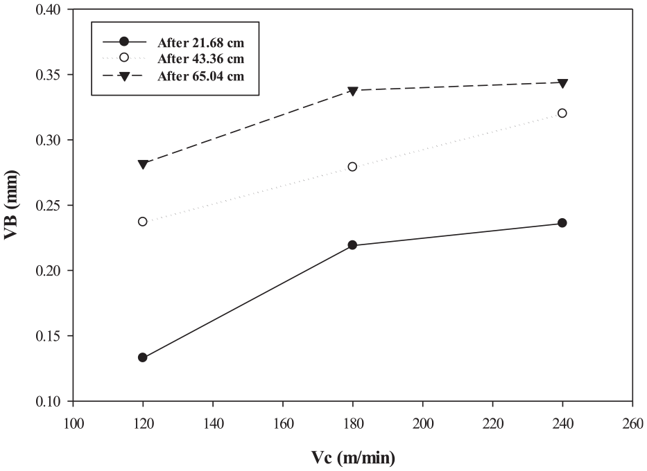
In order to assess the flank wear morphology and size, the lubrication modes used, the flank wear was measured at the end of each pass (Figure 2) in all three lubrication modes used. According to Figure 13, it can be underlined that despite the cutting speed used, increased cutting length led to a higher wear rate. Based on Figure 14, it appears that MQL was more successful than dry mode by means of tool wear reduction. The wear rate under similar cutting conditions has decreased relative to dry mode. In fact, under dry cutting tests, the similar cutting tool reached to maximum flank wear (VBmax) at the second cutting tests while under similar conditions at MQL, 43.63 cm of machining could be conducted with the non-worn cutting tool. According to Figures 14 and 15, no significant difference could be observed between the recorded values of VB under both MQL and wet mode. As similar to the MQL mode, 43.63 cm of machining could be conducted with a non-worn cutting tool under wet mode. The third machining pass led to complete deterioration of the tool’s sharpness in both MQL and wet modes, and completely worn tools resulted. Furthermore, irrespective of the length of cut and the lubrication mode used, higher cutting speed led to increased flank wear. This reveals that although the material structure is non-homogeneous, however, the cutting speed still has a direct influence on the tool wear. However, additional parametric studies by evaluating the effects of cutting speed on tool wear modes and size under various lubrication strategies are suggested.
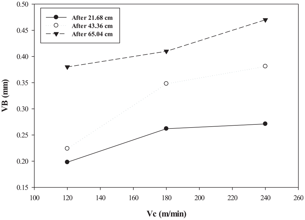
Variation of flank wear under different cutting speeds in dry mode.
Variation of flank wear under different cutting speeds in the MQL mode.
Variation of flank wear under different cutting speeds in wet mode.
According to Figure 16, it can be expressed that at cutting speed 120 m/min, the wear in the wet mode was significantly lower than the dry and MQL modes. This can be related to the intense effects of an additional amount of lubricants on temperature and friction defect reduction in the cutting zone, which tend to prolong the tool life. Based on Figure 17, when a higher level of cutting speed (180 m/min) was used, higher tool wear appears in dry mode while the negligible difference was observed between tool wear readings in wet and MQL modes. It exhibited the effects of lubrication mode at a higher level of cutting speed are not significantly tangible. However, it can also be observed that when machining time increases, higher tool wear is resulted as compared with readings made under wet mode. In fact, at a higher level of cutting speed, friction at the surface of the tool-workpart and the workpart surface increases. Knowing that the flow rate of the cutting fluid in the MQL method is low, the cooling efficiency and lubrication efficiency decrease with increasing contact surface; consequently, a higher wear rate is observed at dry mode, followed by MQL and wet modes.
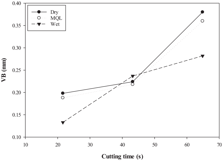
Variation of flank wear under different cutting time in cutting speed of 120 m/min.
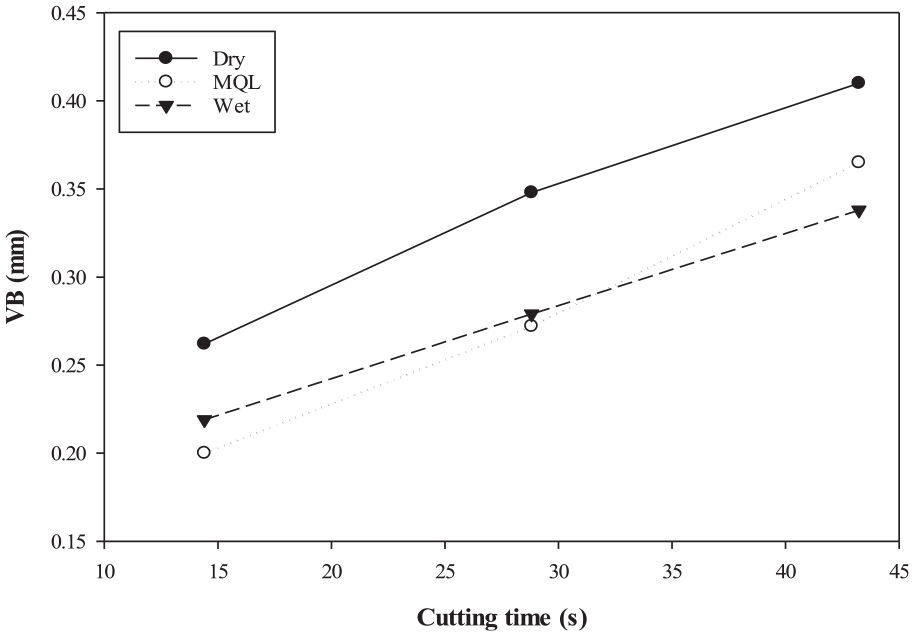
Variation of flank wear under different cutting time in cutting speed of 180 m/min.
According to Figures 16–18, when cutting speed 180 m/min was used, the lower resulted values of machining time were observed. Furthermore, better results were found in wet mode at higher cutting length. Moreover, the slope of variation of tool wear vs cutting time was slower in the wet mode as compared with the other two cases. This observation exhibits the effects of the volume of lubrication on the reduction of generated heat temperature in the cutting zone.
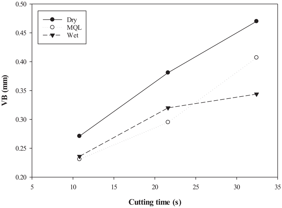
Variation of flank wear under different cutting time in cutting speed of 240 m/min.
Surface roughness
Knowing that Al-MMC is hard to cut material, an adequate selection of initial cutting conditions may affect the surface quality. To better define the surface quality attributes, the average surface roughness, denoted as Ra, was used as the surface roughness attribute in this work. In this study and according to cutting speeds and three lubrication modes used, the surface roughness was measured in three points: first, middle, and end of each pass. Except for minor cases and despite the cutting speed used, it can be observed that larger values of Ra were found at the dry conditions. Furthermore, under the dry mode, the highest values of Ra were recorded at the entrance. This can be related to the collision between the tool and the workpart in a very short time, which generates thermo-mechanical shocks. Accordingly, small-medium scratches were generated on the workpart surface. To reduce the impacts of the cutting tool on the workpart edges, it is necessary to use the most reliable tool path approach, capable of optimizing the exit and entrance sequence of the cutting edge, geometrical elements of the cutting tool, including inclination angle, rake angle, as well as nose radius. Lower values of Ra were recorded in the entrance side under MQL and wet lubrication modes. It is expected that the cutting tool/workpart interaction zone is less affected by thermo-mechanical shocks. However, further experimental works are needed to validate this hypothesis. According to Figure 19, it can be seen that except for minor cases, no systematic relationship can be established between the resulted values of Ra at each pass and lubrication modes used. It is not possible to state that the use of lubrication may undoubtedly lead to improved surface quality. This can be due to the presence of SiC reinforcing particles as well as the material structure, which recovers its hardness and resist against cutting operation under lubricated modes.
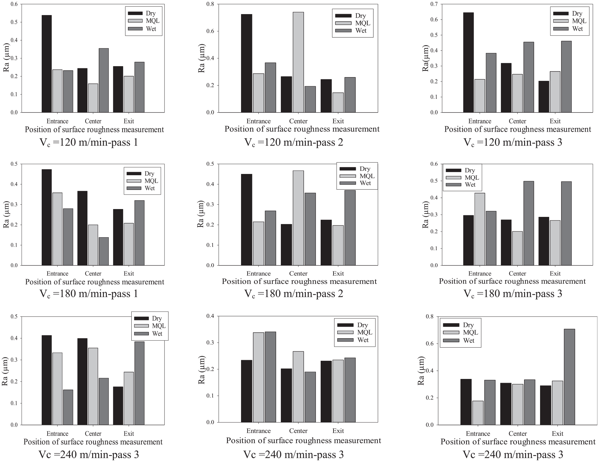
Variation of surface roughness Ra under different conditions.
Conclusion
In the course of this study, the maximum flank wear, tool wear modes, as well as the average surface roughness Ra were recorded under dry, MQL, and wet milling of Al-MMC (A356) reinforced with 10% SiC elements. This study can be concluded as follows:
The BUE was observed under all lubrication modes and cutting speeds used. In addition, the abrasion wear was seen on both rake and flank faces. The main reason for this phenomenon can be related to interactions between hardcore particles with SiC elements, which may lead to coating removal from the cutting tool surface.
Less BUE was observed at lower cutting speeds. This phenomenon can be related to the less generated temperature at lower cutting speeds. In addition to the abrasion and BUE, the diffusion, oxidation, as well as cracks were observed at the tool nose radius. In fact, at a higher temperature, a higher tendency to exchange atoms between the tool and the workpart may occur. Eventually, regardless of the lubrication mode used, diffusion is one of the most widely observed wear modes at higher levels of cutting speed.
The biggest BUE under MQL mode was created at cutting speed 120 m/min, which can be attributed as the critical speed with a higher tendency to BUE formation. Under similar lubrication mode and higher levels of cutting speed (240 m/min), the BUE with a relatively large area was created instead of BUL. Abrasion was also observed under MQL mode. Cutting speed, the BUE, and BUL were reduced, and only the tendency to abrasion mode was increased at higher levels of cutting speed.
It was exhibited that the use of lubricant prevents extension of BUE, and only at a high shear rate with a BUL that has a low thickness on the rake face and flank face of the tool, an extension may occur, and consequently, progressive tool wear may occur. Knowing that in wet mode, a large volume of fluid is injected into the cutting region, the friction tends to decrease much faster than the other two lubrication modes. It was underlined that the BUE was not sensitive to the variation of cutting speed during wet machining.
In general, it was observed that when BUL began to form, consequently, BUE was also created. The growth rate of BUE may vary with respect to the length of cut and cutting speed used. According to experimental results, the use of MQL and wet modes led to reduced temperature and cracking in the cutting area. Subsequently, less flank wear VB was observed as compared with readings made under dry mode.
Ra measurement indicated that except minor cases and despite the cutting speed used, larger values of Ra were observed at the dry condition. Furthermore, under dry conditions, the highest values of Ra were recorded at the entrance side of the workpart. This phenomenon can be related to the collision between the tool and the workpart in a very short time, which generates thermo-mechanical shocks. Accordingly, small-medium scratches were generated on the workpart surface. Also, due to the presence of SiC reinforcing particles as well as the material structure which recovers its hardness and resist against cutting operation under lubricated modes, no systematic relationship can be established between the resulted values of Ra at each pass and lubrication modes used.
Specific attention should be paid to study the effects of other reinforcing elements and particulate (e.g. Bi, Sn) in the machinability evaluation of A356-MMC. Furthermore, Due to the complex shape and morphology of MMCs, and no systematic effects of cutting parameters on their machinability attributes, the use of advanced optimization methods is needed for multiple response optimization. This could be considered as the subject of prospective research works.
Footnotes
Declaration of conflicting interests
The author(s) declared no potential conflicts of interest with respect to the research, authorship, and/or publication of this article.
Funding
The author(s) received no financial support for the research, authorship, and/or publication of this article.