
Abstract
Safety and reliability are significant in the sense of robotic machining for large-scale workpieces. In this article, a control scheme is proposed to ensure the safe motion of the mobile robot. Screw theory is used to analyze the motion of the mobile robot. The mobile platform with Mecanum wheels can be considered as a mechanism with four driven screws in series. An auxiliary reference position of the mobile platform is calculated based on the kinematic model, and the motion of the mobile platform and robot arm can be decoupled to handle its redundant degrees of freedom. Constant speed control is investigated to reduce the interaction force between the robot and platform. Experiments are conducted on the mobile robotic machining task for a large-scale wind turbine blade. The mobile robot moves steadily and smoothly owing to the constant speed control with an auxiliary target.
Introduction
Robots are currently used in industrial machining operations due to the advantages of large operation reach and low cost. 1 Since robots are normally with low stiffness compared to machining tools, 2 they work on machining tasks with relatively low cutting force, such as robotic polishing, 3 robotic boring, 4 and so on. To further increase the workspace of the robots, mobile robotic machining systems are proposed by combining a robot arm with a mobile platform.5–7 As the mobile platform can move to the arbitrary work station, the mobile robotic machining system has a large workspace and ability to machine large-scale workpieces, such as coaches of high-speed trains, wind turbine blades, and aeronautical structures.
On the one hand, the mobile platform can enhance the workspace of the machining system. On the other hand, the accuracy of the mobile robotic machining system is generally low by introducing the mobile platform. To improve the motion accuracy of the mobile robot, closed-loop control is used to compensate for the motion error of the platform and robot arm. Chen et al. 8 summarized the difficulties of control of mobile robots: the redundancy degree of freedom (DOF); the interacted dynamics between the robot arm and mobile platform; and their different constraints (a mobile platform has nonholonomic constraint while a manipulator is unconstraint). To handle the redundancy problem, Bayle et al.9,10 proposed a control scheme by the inverse kinematic model of mobile robots, where a nonholonomic base with a 2-DOF manipulator has been considered. A similar control concept was also studied by Varela-Aldás et al. 11 Galicki presented a feedback control by solving the inverse kinematics problem for mobile manipulators, where the Frechet differential of a certain criterion function is used to solve the inverse problem. Later, he proposed a real-time trajectory generation algorithm of mobile manipulators to control the accurate positioning of the end-effector, where various terminal sliding modes are used to solve the kinematic redundancy. 12 Due to the redundant DOF of the mobile robot, and pseudoinverse techniques are utilized to resolve mobile manipulator redundancy. The main disadvantage related to the pseudoinverse techniques is the lack of obstacle influence on the end-effector movement. 12 Also, the interaction force between the robot arm and mobile platform is not considered during kinematic control.
With respect to the dynamic model of the mobile robot, the mobile platform and robot arm can be treated as two subsystems and an interaction force may exist between the arm and the base. Based on this consideration, Liu and Lewis 13 developed a decentralized robust controller of the mobile robot and proved that the two interconnected subsystems are stable if the interconnections are bounded. If the interconnection force can be measured, Hootsmans and Dubowsky 14 presented a dynamic control method to compensate the interconnection force based on an extended Jacobian. Yamamoto 15 studied the coordinate issue between the base and the arm. Mazur 16 studied the tracking control for different types of nonholonomic mobile manipulators. More references related to the coordinate control of mobile robots can be found in Khatib et al., 17 Tahboub, 18 and Chung et al. 19 It should be noted that the precise knowledge of the mobile manipulator dynamics is normally the preconditions to design the coordinate control. In practice, the precise dynamic model is hard to obtain. Jiang et al. 20 proposed a bioinspired control design for omnidirectional mobile robots, where a cerebellar model articulation controller neural network is constructed to learn the complex dynamics of the omnidirectional mobile robot. But the payload dynamics, dynamics of interactions between the base and the arm, and unknown disturbances such as machining force are complex and time-varying, which is hard to be estimated online and in real time.
In this article, a constant speed control scheme with subtarget is proposed to solve the control issue of a mobile robot for large-scale workpiece machining. In the beginning, the screw theory is used to model the kinematics of mobile robots.21–23 According to the screw theory, the kinematic model can be expressed in a geometric way. It is found that the Mecanum wheels-driven platform is equivalent to an instantaneous serial mechanism with four driven screws. The motion of the end-effector consists of the combined motion of 10 individual driven screws (six driven screws of the robot arm and four driven screws of the platform). This indicates that the mobile platform and robot arm have the same constraints. Then, to decouple the redundancy DOF of mobile robots, an auxiliary subtarget of the mobile platform is defined according to the machining condition. In the end, constant speed control based on the inverse kinematics is proposed to control the mobile platform and robot arm. Since the mobile platform and robot are moving with constant speed, the interactive force between the robot arm and the platform can be reduced. This article aims to provide an easy but reliable method to solve the control issue for the mobile robotic machining, which ensures safety and reliability of the machining process. Simulation and experimental studies are presented to testify the efficiency of the proposed control method.
The remainder of the article is organized as follows. The section “Kinematic analysis of mobile robot” presents the kinematic model of the mobile robot in the sense of screw theory. The section “Control of mobile robot” proposes a control scheme of the mobile robot, where an auxiliary target of the mobile platform is designed. The section “Simulation study” provides the simulation studies to compare the performance of the control with and without the auxiliary target. The section “Experiment investigation” presents the experimental investigation. Finally, some concluding remarks are made in the section “Conclusion.”
Kinematic analysis of mobile robot
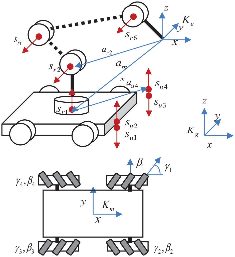
To machine the large-scale component, such as the coach of high-speed trains, large-scale wind turbine blades, and so on, a mobile robot is proposed in this article. The mobile robot consists of a mobile platform with an industrial robot arm. The mobile platform is driven by four Mecanum wheels, while the robot is with 6 DOFs.
In this article, the screw theorem is introduced to describe the kinematic model of the mobile robot.21,24 A coordinate system Ke is attached at the end-effector of the mobile robot, and Km is attached at the mass center of the mobile platform. Both coordinates parallel to the global coordinate Kg, as shown in Figure 1. The screw in six-dimensional space
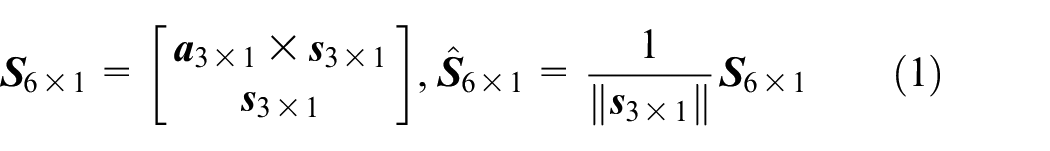
where

where
where
Kinematic model of the mobile robot.
To calculate
where
The motion of the mobile platform is described as follows
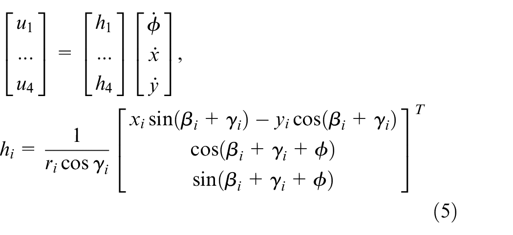
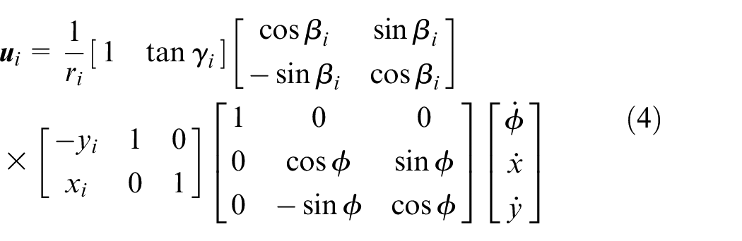
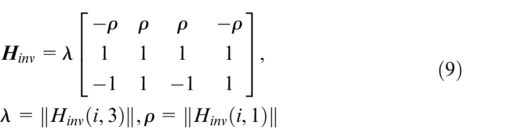
If the Mecanum wheels are arranged as follows (shown in Figure 1)
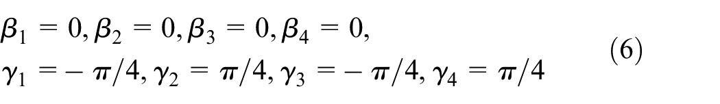
the kinematic model of the mobile platform is
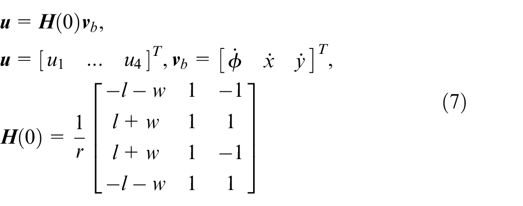
where
The motion of the mobile platform lies in a plane. It is possible to expand the planar motion into a six-dimensional space
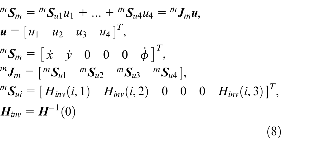
where
where
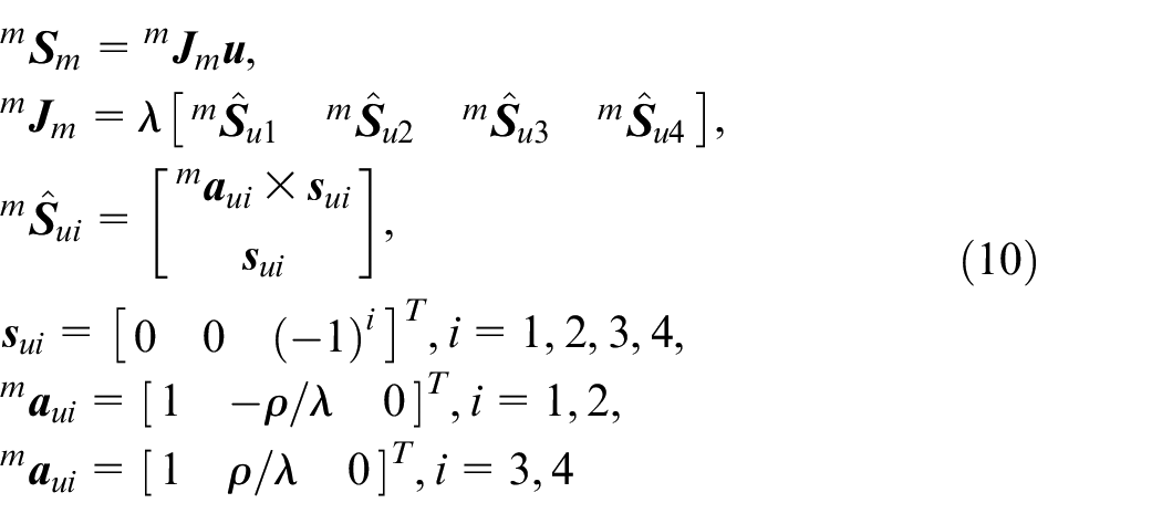
where
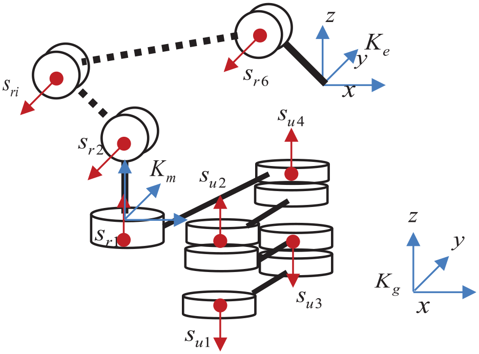
Equivalent kinematic model of the mobile robot.
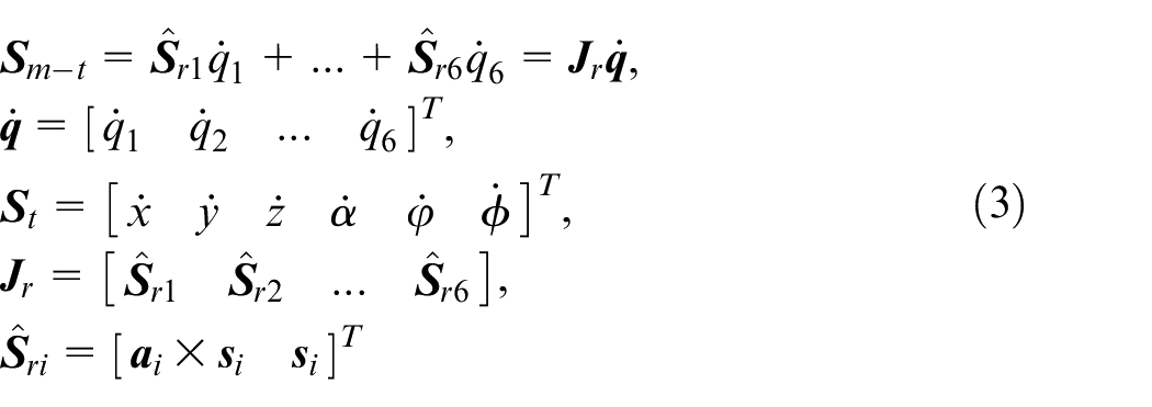
Transforming the screw from the center of the mobile platform to the end-effector of the robot, we have
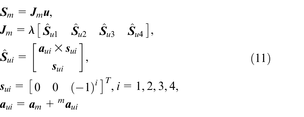
where
Substituting equations (3) and (11) into equation (2), we have the kinematic model of the mobile robot expressed by screws
Then, the position of the end-effector can be expressed by
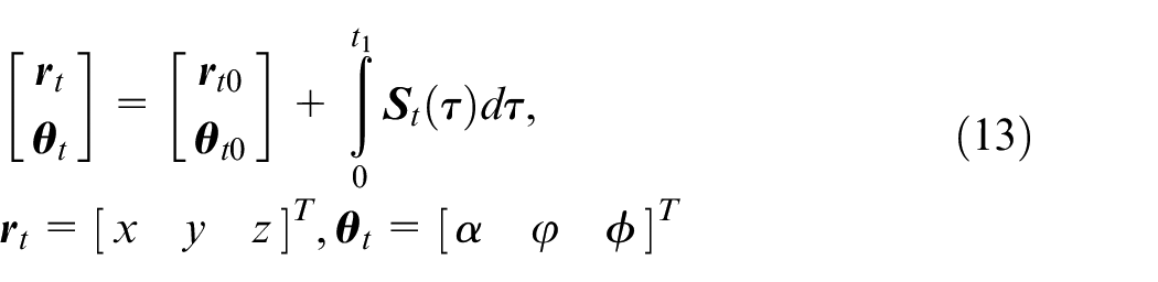
where
Control of mobile robot
Control without subtarget
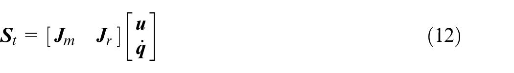
The end-effector of the mobile robot is with 6 DOFs but with 10 actors, which is a redundant driven system. For such a system, the pseudoinverse operator is widely used to solve the control issue. In general, the control input is given as
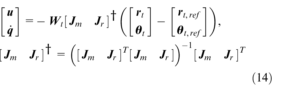
where
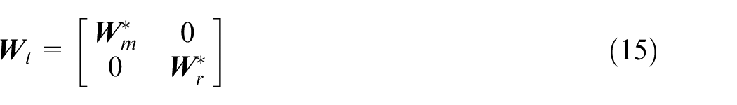
The weight matrix indicates the input energy of the mobile platform and robot. Since the mass of the mobile platform is much larger than the robot, the weight matrix is given as
To analyze the stability of the system under control, the Lyapunov function is constructed with the error between the reference and the real posture
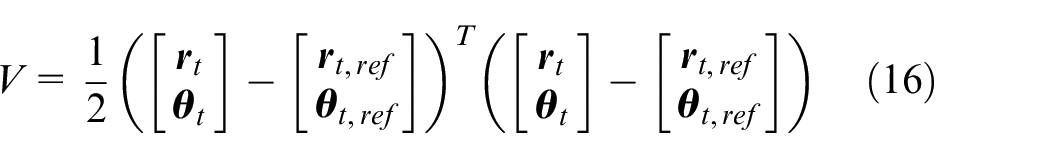
The derivation of the Lyapunov function is
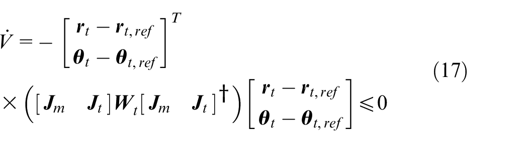
Equation (17) indicates that the error converges to zero when time goes to infinity.
To ensure a safe motion in the machining environment, the motion of the mobile platform should be also controlled. If we check the motion of the mobile platform
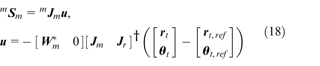
Integrating equation (18), we have
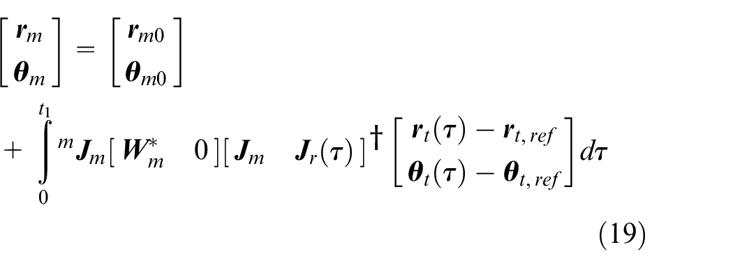
Equation (19) indicates that
Control with subtarget
For any given target posture of the end-effector, it is possible to find map function as
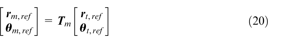
where
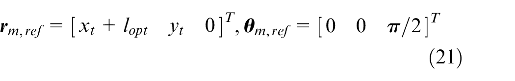
where
Then, the reference of the end-effector related to the mobile platform is given as
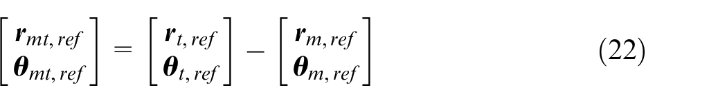
where
Based on the subtargets, the control of the mobile platform and robot can be separately designed. The control input of the mobile platform is given as
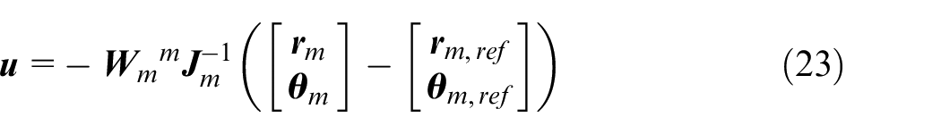
where
Correspondingly, the control of the robot arm is
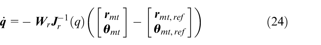
where
To analyze the system stability under the control with subtarget, a Lyapunov function is constructed as
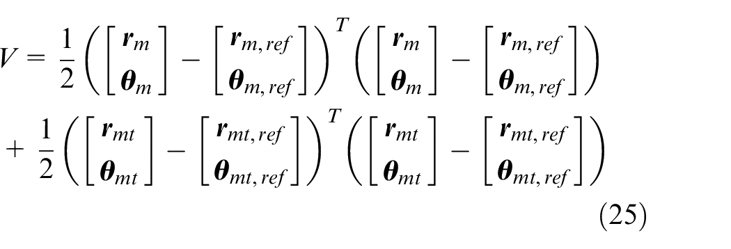
Taking the derivative of equation (25)
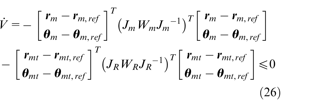
Equation (26) indicates that the controlled system is stable. Then, the control error approaches to zero when time goes to infinity
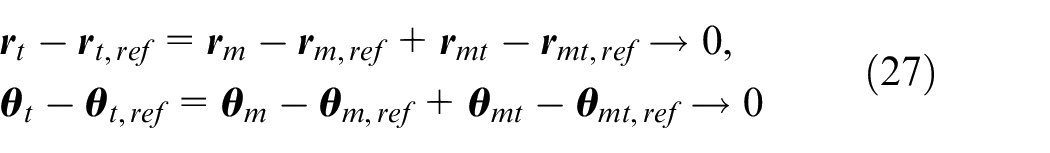
Since the mobile platform and the robot arm reach the reference postures, the end-effector will also achieve the target posture. The advantage of the control with subtargets is that the redundant driven issue can be solved by the planning technique, and meanwhile the system reliability can be ensured.
Constant speed control with subtarget
To reduce the interaction force between the mobile platform and robot arm, a constant speed motion is desired. Thus, a smooth switching function is introduced to describe the input of the mobile platform and robot arm
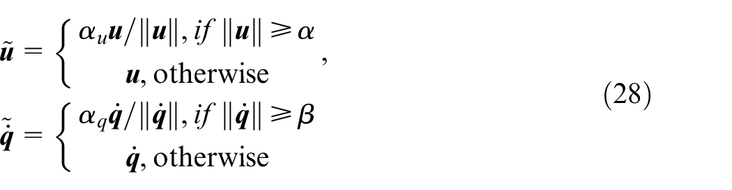
where
Simulation study
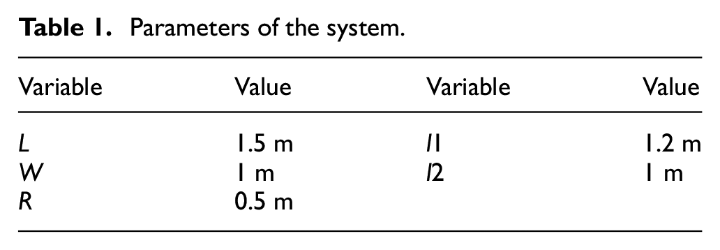
A numerical simulation study is carried out in this section to compare the two control schemes, that is, without subtarget and with subtarget. The parameters of the system are given in Table 1. To simplify the analysis, the center of the mobile platform is assumed to coincide with the first axis of the robot. In the simulation study, the mobile platform and the first three joints of the robot are controlled.
Parameters of the system.
The initial posture of the mobile robot is
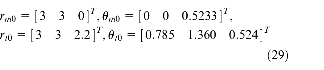
where

The weight matrix in the simulation study is given as
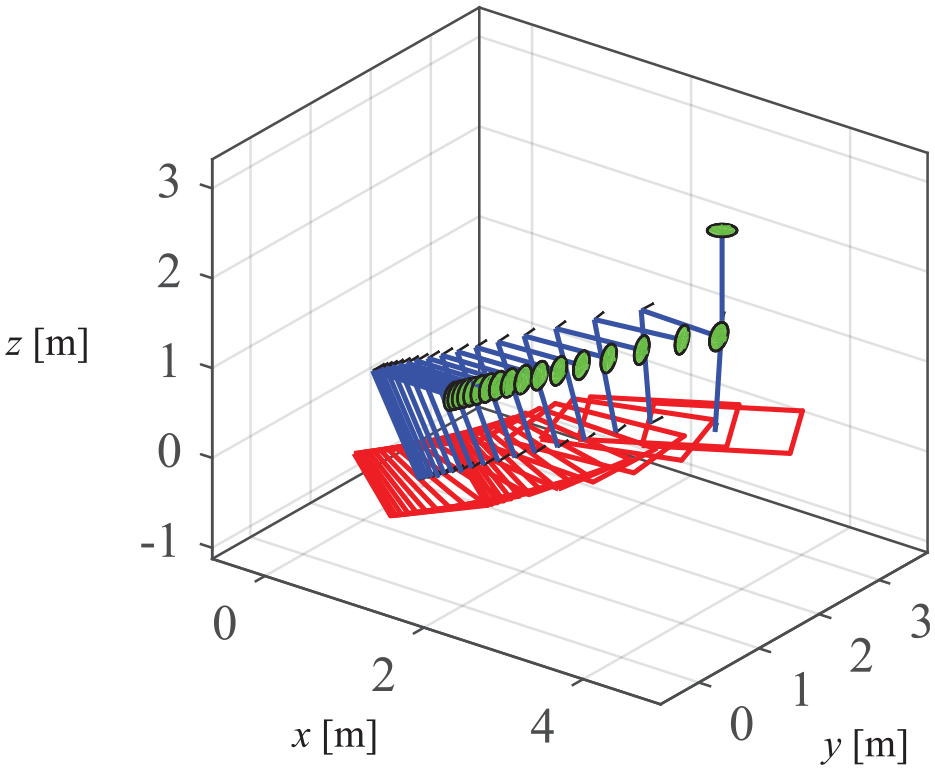
Trajectories of the mobile robot under the control without subtarget.
Control error and input value under the control without subtarget. (a) shows the control error, (b) shows the control input of the mobile robot, and (c) shows the control input of the robot arm.
Trajectories of the mobile platform with different initial positions under the control without subtarget.
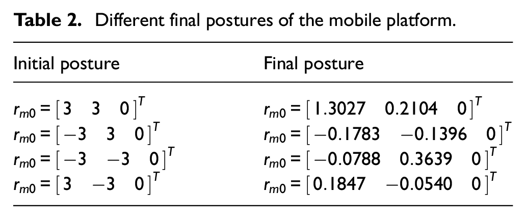
Different final postures of the mobile platform.
To cope with the disadvantage of the control without subtarget, an auxiliary target for the mobile platform is given as

Then, the reference of the end-effector related to the mobile platform is

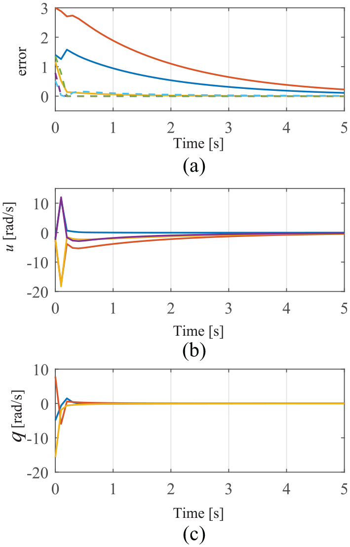
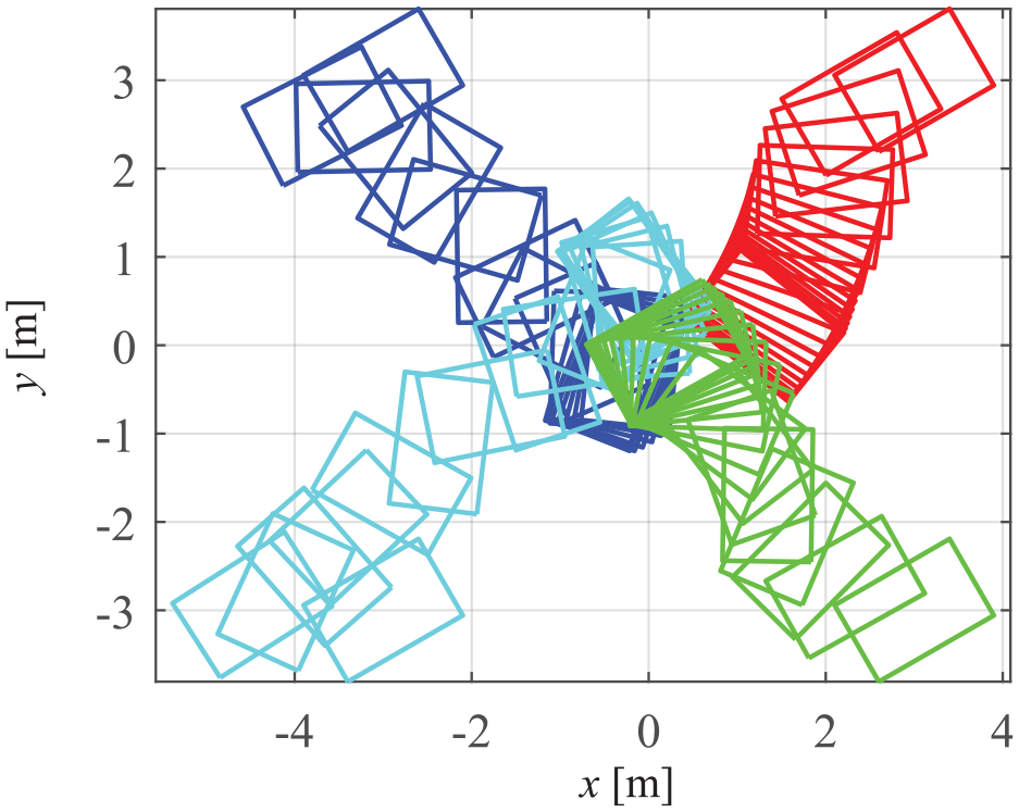
Figure 6 describes the trajectories of the mobile robot under the control with subtarget. Thanks to the subtarget, the mobile platform and the robot arm can move independently. Figure 7 shows the control error and the input value of the mobile robot over time. The input value of the mobile platform and robot is smooth by using the switch input function given in equation (28). By doing this, the mobile robot can move steadily and the interaction force between the robot and arm can be reduced. Figure 8 shows that the trajectories converge to the auxiliary target with different initial conditions. Since the redundancy-driven system has been decoupled into two subsystems, the control has no difficulty to drive the mobile platform and the robot arm to their reference postures. Simulation results testify the control with subtarget is more reliable for the mobile robot for the machining task, which has a large potential for practical application.
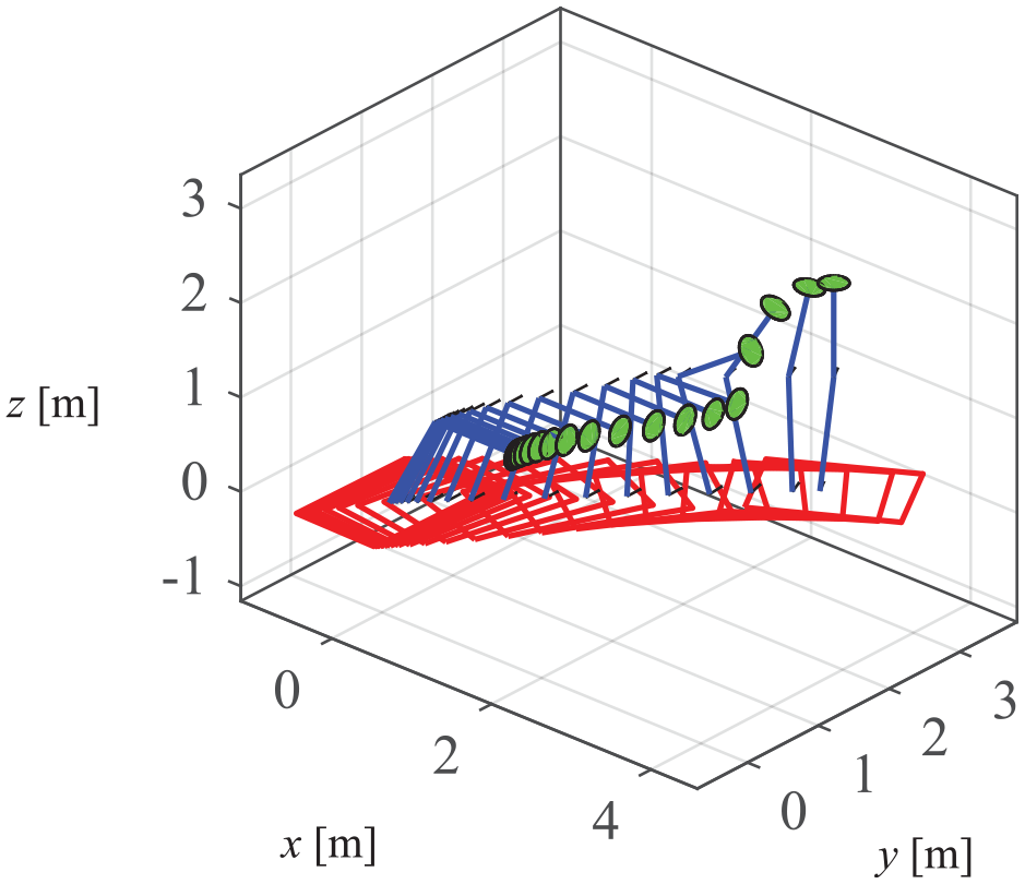
Trajectories of the mobile robot under the control with subtargets.
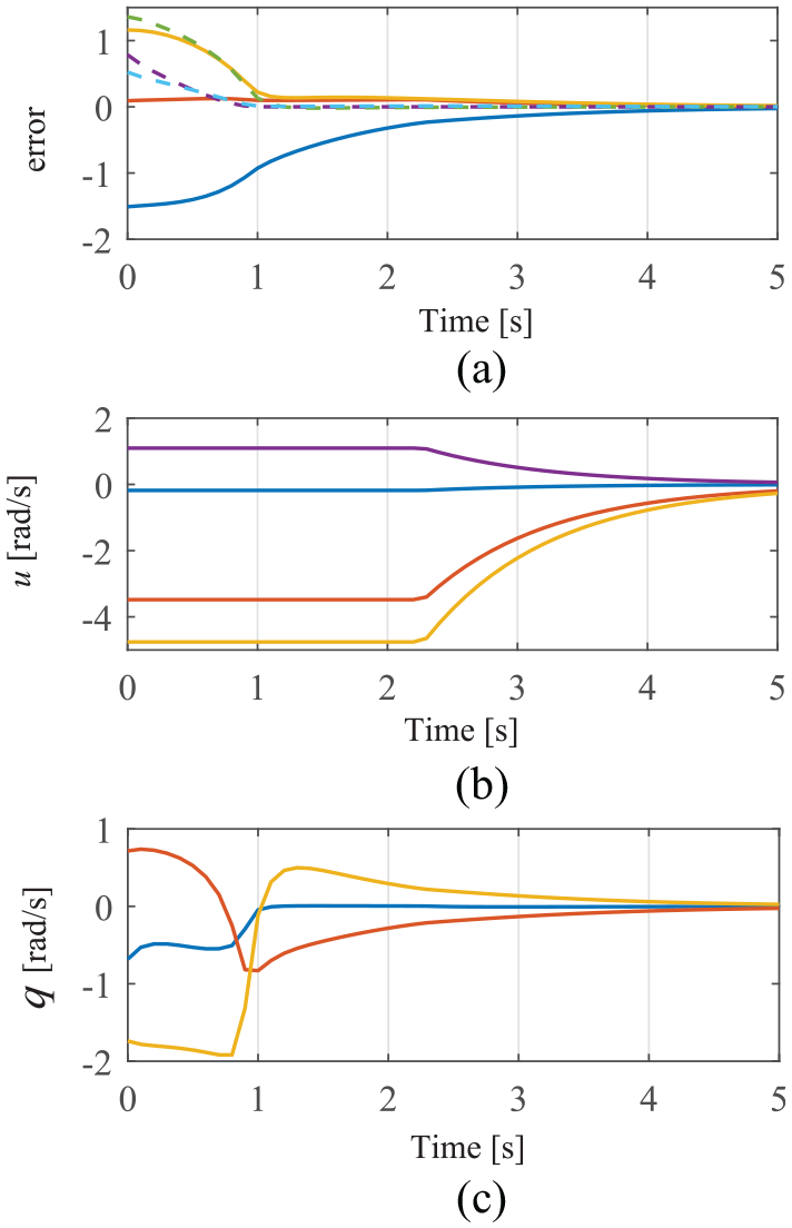
Control error and input value under the control with subtargets. (a) shows the control error, (b) shows the control input of the mobile robot, and (c) shows the control input of the robot arm.
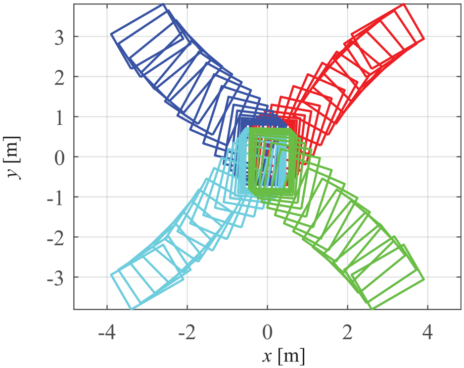
Trajectories of the mobile platform with different initial positions under the control with subtargets.
Experiment investigation
In this part, a mobile robotic machining system is constructed as shown in Figure 9. The mobile robotic system consists of a mobile platform driven by four Mecanum wheels and an ABB-4600 robot arm. The workpiece is a wind turbine blade. The motion capture system (Optitrack) produced by NaturalPoint, Inc. is used for global localization of the mobile robot and the workpiece. To localize the motion of a rigid body, the rigid body should be at least observed by two cameras. Figure 10 shows the layout of the cameras, so that the whole workspace of the mobile robot can be observed.
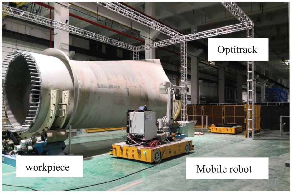
Mobile robotic machining system for a large-scale workpiece.
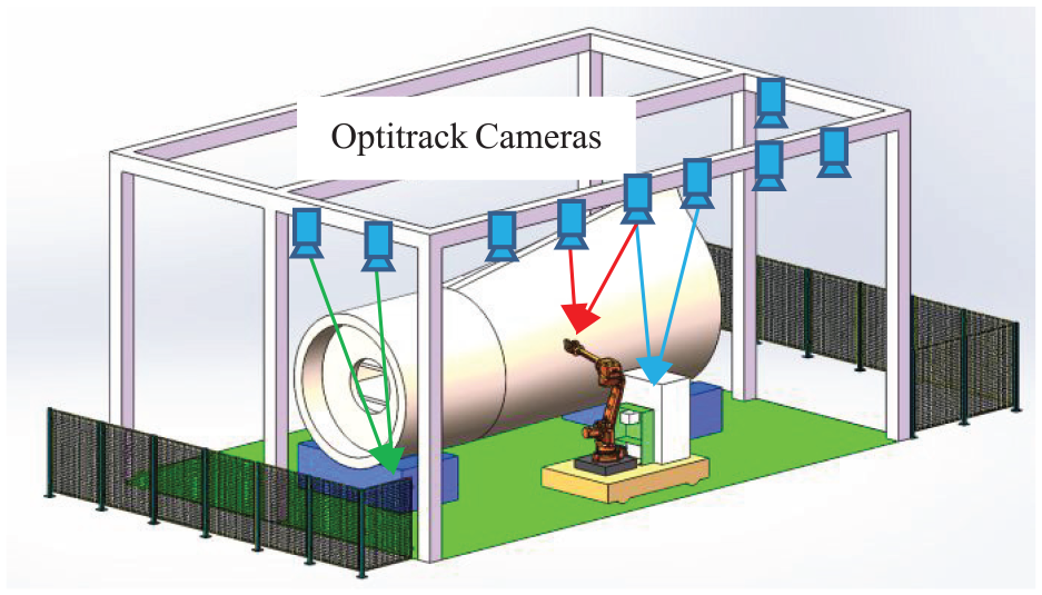
Global measurement system.
The Socket communication is used to transfer the data within the Optitrack, robot arm, and mobile platform. The input of the mobile platform is the speed of wheels, and the posture of the platform measured by the Optitrack is the output. The input of the robot arm is the speed of each joint. The end-effector of the robot can be calculated by forward kinematics of the robot arm as the output. The control sample time is set as 0.1 s. The mobile platform is with its length 1.5 m and width 1 m. The type of the robot arm is ABB-4600, whose detailed data can be found in an official datasheet.
To machine the large-scale workpiece, the robot arm and the mobile platform move alternately. In the beginning, the mobile platform moves to the designed station. Then, the robot arm moves along the designed trajectory to machine the surface of the workpiece. Once the region to be machined is out of the workspace of the robot arm, the platform moves to the next station. In this way, a large workpiece can be machined piece by piece.
Experiments will be carried out to testify the feasibility of the technology process. Figure 11 shows the trajectory of the mobile platform recorded by the Optitrack. The mobile platform is controlled to approach the designed position
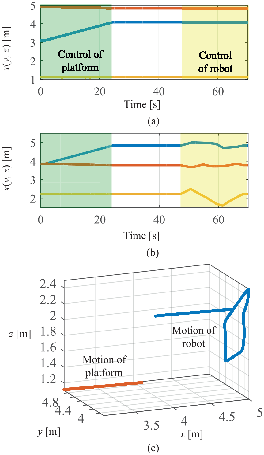
Trajectories of mobile robot recorded by the Optitrack: (a) the trajectory of the mobile platform, (b) the trajectory of robot arm, and (c) the trajectory of mobile robot in three dimensions.
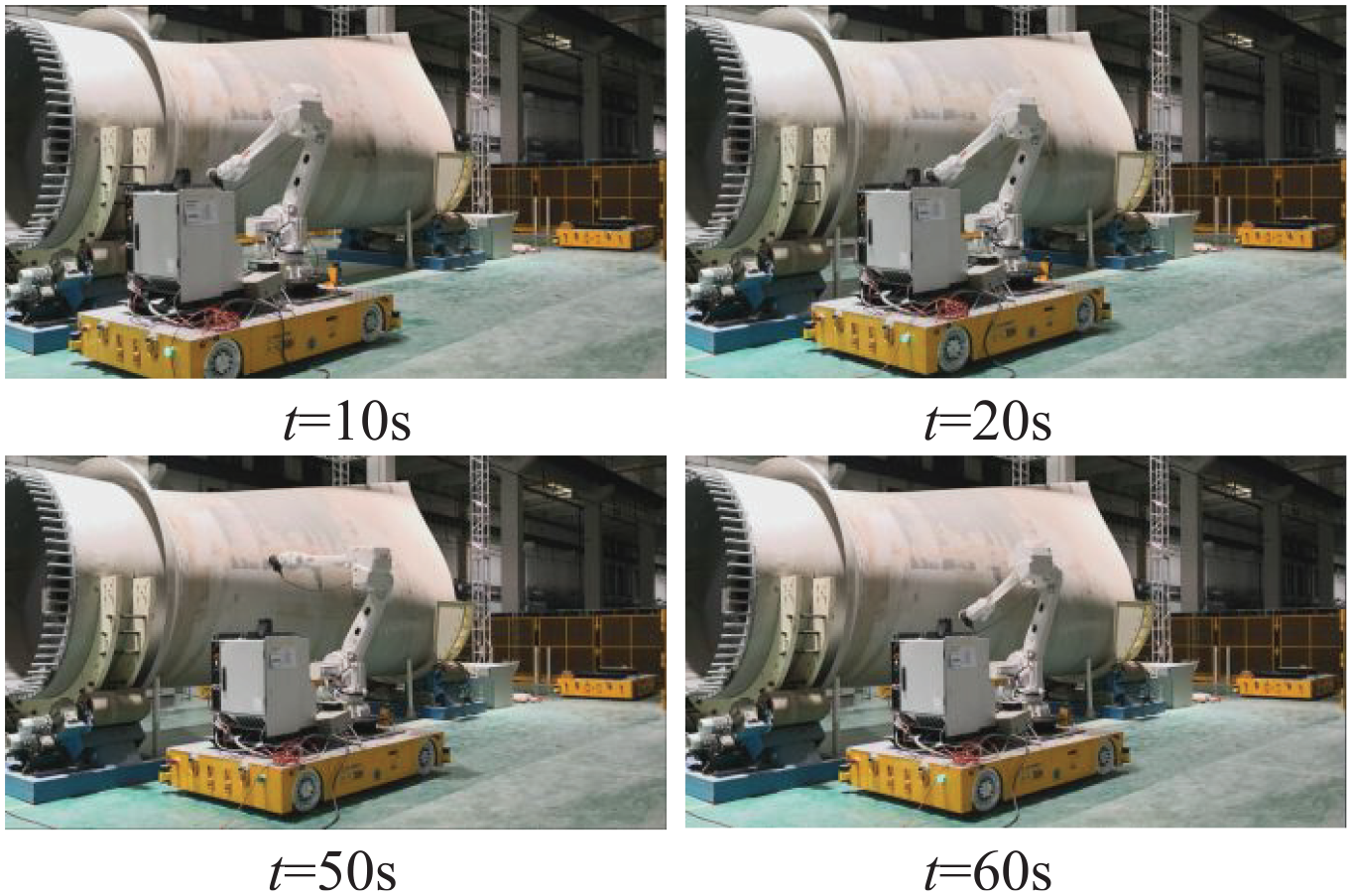
Poses of the mobile robot at different instants: t = 10 s, t = 20 s, t = 50 s, and t = 60 s.
Conclusion
In this article, a mobile robot is set up for large-scale workpiece machining, which consists of a mobile robot with an industrial robot. The kinematic model of the mobile robot is investigated by the screw theory. According to the screw expression, it is found that the mobile platform driven by four Mecanum wheels is equivalent to a mechanism with four driven screws in series. Based on the kinematic model, a control strategy of the mobile platform featured by an auxiliary target is proposed. The auxiliary target gives the reference posture of the mobile platform according to the machining condition. Then, the control of the mobile robot can be decoupled as the control of the mobile platform and the control of the robot arm. Constant speed control based on the inverse kinematics is proposed to reduce the interaction force between the mobile platform and the robot arm. Based on the control scheme, mobile robotic machining for large-scale workpieces becomes feasible. Simulation and experiment studies testify the performance of the control strategy.
Footnotes
Declaration of conflicting interests
The author(s) declared no potential conflicts of interest with respect to the research, authorship, and/or publication of this article.
Funding
The author(s) disclosed receipt of the following financial support for the research, authorship, and/or publication of this article: This work was supported in part by the National Science Foundation of China under Grants 91748204, 51905184, and 91948301, in part by the National Key Research and Development Program of China under Grant 2017YFB1301504.