
Abstract
In a discrete manufacturing enterprise, it is difficult to satisfy the fast matching and accurate supply of production materials or the demand of modern dynamic production systems using passive material supply. With a focus on engine builders, this study explores the active material configuration and systematic material distribution approaches. Due to the material characteristics and the granularity of logistics demand, the material distribution is arranged in reverse chronological order, and the corresponding mathematical modeling of the distributing period is proposed to achieve lean manufacturing. To ensure exact material distribution time, the allocation material configuration model that works best for the dynamic manufacturing system is presented by means of system modeling. Next, a production material distribution method for the general assembly line and the sub-assembly line with a closely related production sequence is proposed to achieve the exact match of manufacturing and material resources through the analysis of data fusion and logistics resource matching. Finally, a simulation is conducted using production data gathered from engine builders. The results indicate the effectiveness of the proposed active material configuration method. The outcome of this study can be used as a guide for the time planning of material flow in a dynamic manufacturing system and can provide a new research perspective on production logistics or distribution in a production line.
Keywords
Introduction
Material distribution management is extremely important in the production process of a discrete manufacturing assembly system. As a key part in the whole production process, material distribution connects the integrated logistics services with demand subjects.1–3 Timeliness and accuracy are considered to be two key metrics for measuring the material distribution efficiency. Timely and accurate delivery of materials from the production line to the assembly line is an important guarantee for the successful completion of lean production and is also a major area of focus in academia and the business community. However, investigation of the assembly production process of engine builders reveals that the following issues exist in the distribution process of production materials. Engine builders suffer from inefficient material distribution, and the existing material replenishment mode cannot meet the just-in-time distribution requirements of the production line. Moreover, without uniform management, material packaging on the production site has increased invalid working time during the production process and decreased production efficiency. Furthermore, material demands besides the production line cannot be captured in real time; thus, to meet the demand of continuous production, enterprises must maintain a large amount of material safety inventory besides production lines, which can lead to an increase in waiting time and material inventory. Finally, due to the inconsistency between the production cycle and material distribution at the worksite, workers are sometimes required to complete additional tasks, such as material pickup and unpacking, which can cause production halts. Therefore, research on systematic material distribution is of great significance for lean production and the improvement of enterprise efficiency.
Regarding the optimization of material distribution of the production line, several methods have been reported in the literature. Material requirement planning and enterprise resource planning solved the issue of large-batch logistics distribution among enterprises. 4 Wang et al. 5 presented an efficient scheduling method based on item similarity and task balance principles on a picking line, using which the problem of frequently changing picking channels was resolved. Domingo et al. 6 addressed the problem of intermediate inventory accumulated in the production process, identified the data from value flow graphs, and developed a milk-run routing analysis system on the foundation of inventory, dock-to-dock time, and lean rate to improve material flow. With the actual data of an engine logistics department, Liu 7 achieved the just-in-time distribution and optimum stowage rate of a trolley by analyzing the sequence production-based material distribution model. The authors divided the delivery mode into three types—non-delivery, batch delivery, and sequential delivery. By combining the proposed bill of material (BOM), the remaining parts at each production cycle of each station can be computed to accomplish a sound material distribution. 8 According to the different execution orders of the plan, Jeunet 9 combined the inventory control strategy to predict the quantity of material demand and the demand time window of the production line. Kabak and Ornek 10 studied the impact of scheduling on material distribution and proposed a new measurement mechanism to evaluate the impact of scheduling on the leveling consumption instability of multi-material distribution. Using the system dynamics modeling and simulation principle and related technologies, Lai et al. 11 investigated how to accurately calculate the delivery time, delivery quantity, and delivery frequency in just-in-time production and presented some countermeasures to improve productivity using real-time display. According to the material delivery quantities and the speed of material consumption, Choi proposed and simulated a dynamic parts distribution system to meet the needs of automobile assembly production. Considering the constant production time, the type and quantity of required parts were dynamically estimated and used as the real-time input condition for distribution route planning to optimize the on-line delivery efficiency of production materials. 12 Unlike the current research on material distribution optimization methods in the field of manufacturing, this study mainly focuses on the improvement of the material distribution path, material transportation means, material on-line mode, and inter-enterprise material transportation.13,14
Addressing the issues in the process of material dispatching to the production line in engine assembly, this article investigates a novel method of material distribution. First, the characteristics of the materials on an engine assembly are discussed. The distributed materials are categorized according to the BOM information and the demands at the production workstation. The distribution mode is determined to be quantitative distribution, single distribution on work order, and replenishment distribution. Next, the temporal logic for material distribution to production lines is designed in reverse chronological order. Moreover, the mathematical model of active material configuration for the general assembly line (GAL) and the sub-assembly line (SAL) is developed based on the temporal logic and the material demands on production lines; furthermore, the material distribution interval and the table of distribution time zones (TZ) are obtained. A case study involving production data is presented to verify the effectiveness of the proposed method. Results from this study will provide a guide for effective material flow in the assembly process and a control method for the material dispatching process on the production line.
Production material distribution configuration
Production line material distribution process
In the production process of engine manufacturing enterprises, the material distribution is mainly guided by the master production schedule (MPS). An operation plan is generated according to the MPS to obtain information on material demand and time at the border of the line. 15 The workstation material distribution demand is pulled by production demand to establish a sustainable distribution system. In the process of material distribution, the following rules should be followed: accurate feeding quantity, exact feeding time, paperless feeding, direct feeding to workstation, and separation from production and logistics. 16 Combined with key management factors in engine builders, such as material characteristics (volume, number of unit packages), the distribution principles, and production rhythm, the material distribution mode is classified into three types—quantitative distribution, single-order distribution, and replenishment distribution. The main distribution flowchart of engine builders is provided in Figure 1.
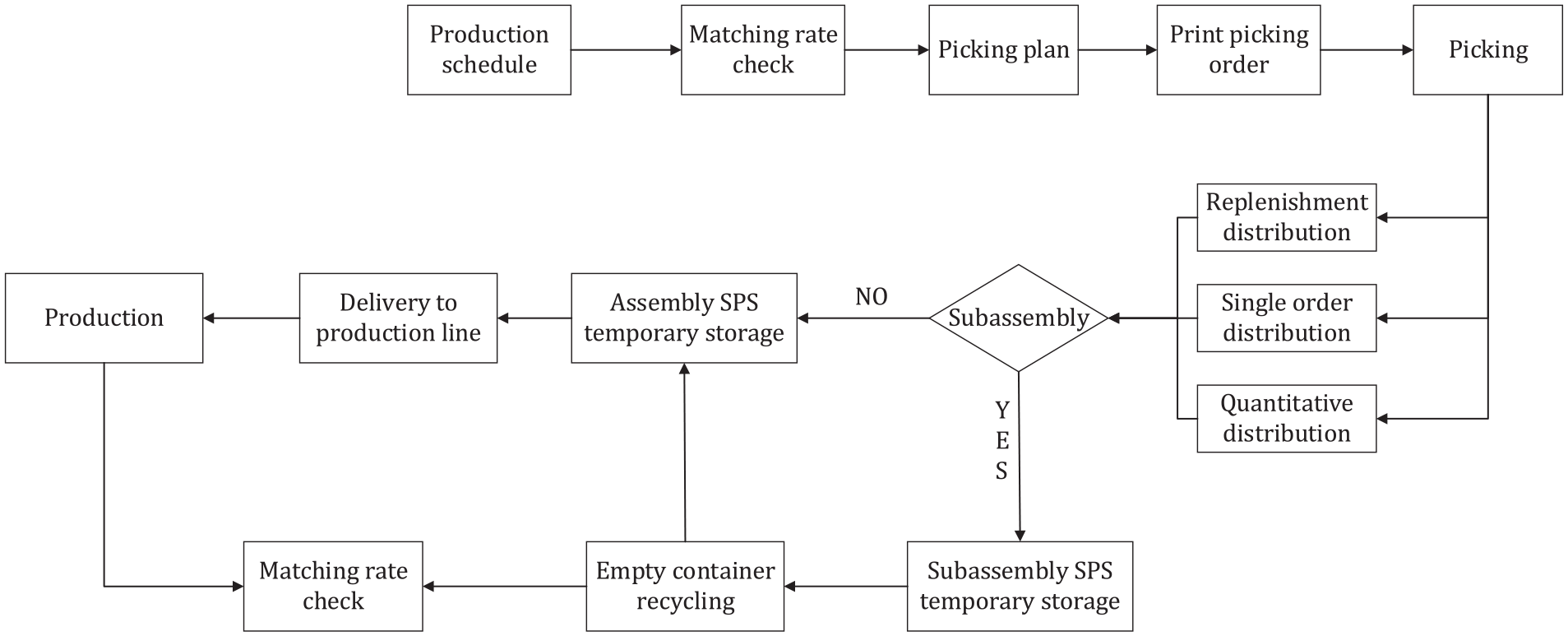
Main distribution flowchart of engine builders.
First, the production and material demand plans for daily operation are formulated through the MPS. 17 Next, the border of line matching should be guaranteed, and then the material matching rate is verified according to the requirements of different materials. The material picking plan is then made after satisfying the matching rate, wherein the picking should take different material distribution modes into consideration. Once the picking completed, materials for sub-assembly are placed in the set parts supply (SPS) area, and materials for general assembly are placed in the general assembly SPS. 18 Finally, the shippers deliver the materials to the corresponding workstation for production according to the preset delivery lead time.
Feeding operation configuration design
An analysis of the flowchart in Figure 1 reveals that the workshop is mainly composed of the SAL and the GAL. The SAL is a discrete production line, which can supply a continuous GAL by assembling the parts needed in advance. Therefore, this study combines the main process of distribution with the design of the time sequence of material distribution by the method of time inversion. That is, the material distribution time, picking time, working time of the SAL, and supplier order to delivery are derived by the information regarding the material demand of the GAL. 19 Subsequently, the deduced working time guides the work of producers and logistics employees. In the process of inversion of service time, different matching rate checking methods should be set for a continuous assembly line according to whether the BOM contains self-made materials. For the case of semi-finished products contained in the BOM, two matching rate checks are required: one is a matching check for feeding GAL and the other is for feeding SAL. 20 For other cases, matching inspection of materials in an assembly workstation (AW) only requires the matching rate to be checked N hours before the start of production according to the requirements of different materials.
Active material resource allocation model of manufacturing systems
The manufacturing system realizes the material resource allocation by utilizing the workstation production time as the criterion to pull the material demand. There is a strict time sequence relationship between the material demand of the GAL and the SAL workstations. Distribution sequential logic describes the material flow process in the horizontal direction. In particular, it specifies the time between the arrival of materials from suppliers to the assembly line. 21 The batch distribution interval mainly regulates the time of material vertical flow. That is, based on the relationships in distribution sequence logic, the working time in the process of material distribution to production and the assembly line is accurately determined. This study classifies the material distribution modes of the GAL and the SAL into three types. Among them, quantitative distribution is mainly given in pcs of hours. According to the unit information table of materials and material distribution tools, the border of the line is prepared in hours and then distributed in batches according to the production quantity determined by the main production operation plan. For assembly line production, the replenishment interval of materials with quantitative batch distribution depends on the production rhythm and quantity of batch distribution at each station on the assembly line.
Establishment of distribution interval model of GAL
For assembly line production, the start time of batch production is delayed with an increase in the number of workstations. However, the start time of batch distribution is determined by the start time of batch production. Therefore, the batch replenishment time can be determined by calculating the start time of batch production. The equation for calculating the start time of batch production on an assembly line is given as
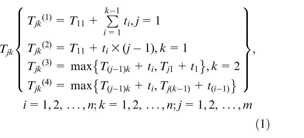
where i and k are the assembly process numbers, j is the serial number of the engine produced on the GAL, ti is the assembly time of the assembly shop i, and Tjk is the start time of product j on AW k.
Using the mathematical model defined in equation (1), the production start time of each product on the GAL of each process is calculated. The steps of calculation are as follows:
Based on Tjk(1) and Tjk(2), the production start time of the first product on every AW and the start time of the first AW for all products are calculated, respectively.
The start time of the second product on the second station and the second product on every workstation of the GAL are calculated by Tjk(3) and Tjk(4), respectively.
Similarly, the production start times of all products are calculated accordingly.
After calculating the batch production start time of all processes in the assembly shop, the production process, working procedure, and logistics operation times are used to calculate the batch distribution time interval of all materials in the assembly workshop. This provides the basis for determining the start time of parts production in the sub-assembly workshop.
Establishment of the distribution interval model of SAL
In the SAL, the feeding time depends on the start time of sub-assembly. According to the production start time and the material demand time of the GAL, the start time of batch production is determined to calculate the feeding interval of the SAL. The start time of batch production for the SAL is calculated as follows
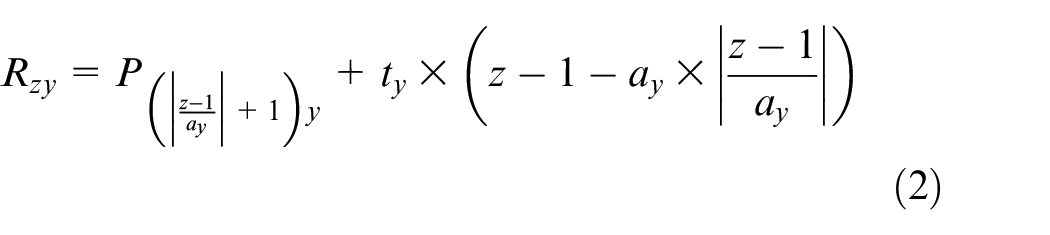
where Rz represents the start time of the SAL for the product z,
According to equation (2) and the start time of batch production, the production start time and feeding time interval of the SAL are calculated. However, some start times of sub-assembly production derived by the demand information of the GAL conflict with the end times of the previous batch. That is, the parts of the previous batch have not been assembled yet, and the next batch production has already begun.
As long as a certain batch production start time conflicts with the previous batch end time, there will be a mismatch in the rest of the batches. To solve this conflict, it is necessary to analyze the production start time and completion time of the materials of the parts and adjust the conflicting schedule. The adjustment method is shown in equations (3) and (4)

where TE1 and TS2 represent the initial inverted end time of the first batch and the initial inverted start time of the second batch at the sub-assembly workstation (SAW), respectively. If
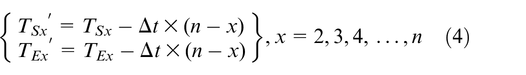
where x represents the production batch number of the SAW; n is the total batch number of the SAW; TSx and TEx represent the initial inverted start time and end time of batch x at the SAW respectively; and TSx′ and TEx′ represent the adjusted start time and end time of batch x at the SAW, respectively.
Production material resource matching check
Calculation of the start time of batch production
A case is studied to verify the effectiveness of the proposed model. Suppose the order of delivery is set to 20 May. Based on the production plan and daily capacity, on 10 May, a work order batch of 100 engines is released to the workshop. The working hours of the workshop are from 8:00 to 12:00 and from 13:30 to 17:30. The last engine in the last process of the assembly line is produced at 17:30 on 19 May.
According to the mathematical model and the computational procedure, the start time of each product on the GAL is determined as follows:
The production start time of the last product on all stations and the production start time of all products on the last station are calculated in reverse chronological order by Tjk(1) and Tjk(2), as depicted in equation (1).
With the computing method of reverse chronological order, the production start time of the penultimate product at the penultimate station is obtained by Tjk(3)and, subsequently, the production start time of the penultimate station product at all stations is scheduled by Tjk 4 .
Similarly, the production start time of the antepenultimate product at the penultimate station and the antepenultimate product at all stations are calculated by Tjk(3) and Tjk(4), respectively. By that analogy, the production start time of the first product on the first station, namely, the start time of the assembly line, can be determined. The start times of each product at any workstation on the GAL are calculated and listed in Table 1.
Finally, based on the calculated production start time of the GAL, the production start time of the batch product at the SAL is calculated by equation (2).
Using equation (2) and the data in Table 1, the batch production start time of the closely related workstations on the SAL is calculated.
Calculation results of production start time of the GAL.
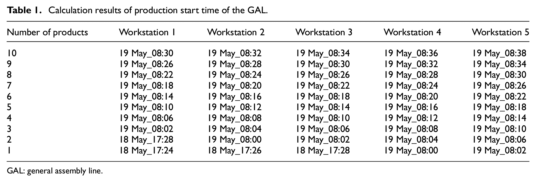
GAL: general assembly line.
Feeding demand time node calculation
Taking the production of piston connecting rod assembly (PCRA) as an example, according to the assembly line production requirements, logistics operation configuration, production rhythm, and the data from Table 1, the feeding time nodes of the GAL and the SAL are calculated.
Feeding time node arrangement for GAL
For PCRA production, on the GAL, the time node of material flow for each batch of 100 pcs, which includes the start time of GAL production, the PCR feeding time, the inspection time of material matching, the end time of SAL production, the SAL production start time, the piston and connecting rod (P&CR) feeding time, and the P&CR cleaning end time and cleaning start time, is arranged under some constraints. The four batch results are listed in Table 2.
Material flow time node for PCRA production.
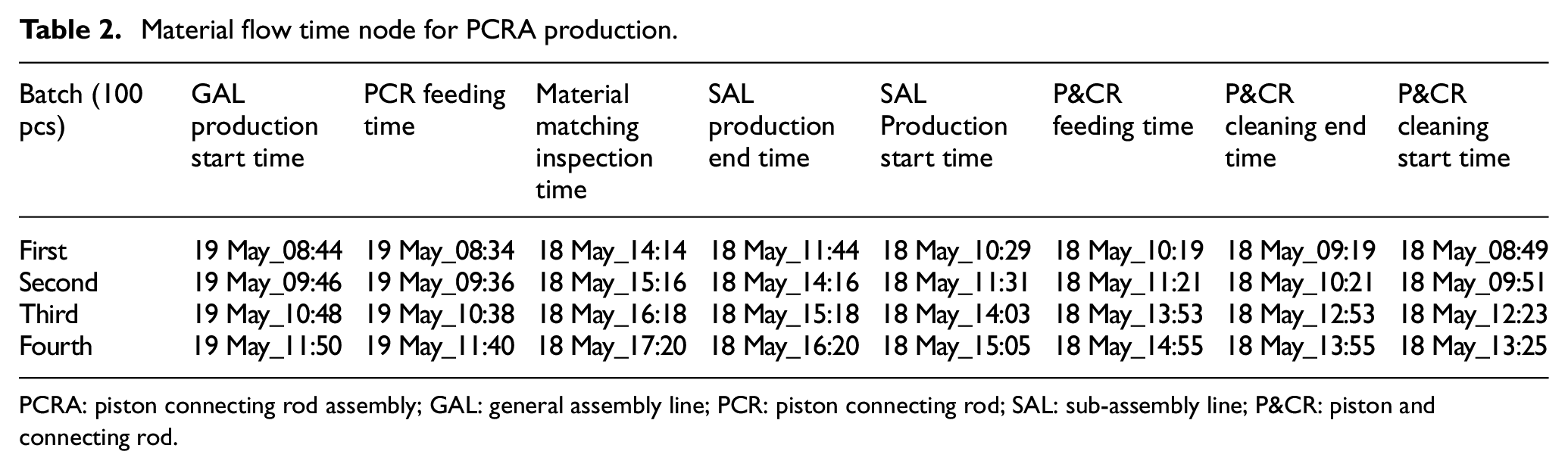
PCRA: piston connecting rod assembly; GAL: general assembly line; PCR: piston connecting rod; SAL: sub-assembly line; P&CR: piston and connecting rod.
The constraints are depicted as follows:
GAL production start time: the start time for PCRA production on GAL (keeping the demand of materials for 2 h besides the line).
PCR feeding time: the time when the PCR is distributed to GAL (10 min before GAL production start time).
Material matching inspection time: the time for inspection of matching material for PCRA production (4 h before GAL production start time).
SAL production end time: the end time for each PCR production batch and placing in the SPS buffer after PCR assembly (at least 1 h before matching inspection).
SAL production start time: the start time for each PCR production batch on SAL (45 s per piece).
P&CR feeding time: the time when the P&CR is distributed to the SAL (10 min before SAL production start time).
P&CR cleaning end time: the end time for P&CR cleaning and placing in the SPS buffer (1 h before feeding time).
P&CR cleaning start time: the start time for P&CR cleaning (cleaning for 30 min).
Inverted material flow time node for SAL
On the SAL, the materials for PCR production include the P&CR, oil ring, hole ring, and piston pin. Under some constraints, the time nodes for P&CR include the time of SAL production start, P&CR feeding, P&CR cleaning end, P&CR cleaning start, and P&CR feeding to cleaning line. For the oil ring, hole ring, and piston pin, the time nodes include the time of material prepared, SAL feeding, picking end, picking start, and picking list print. According to the schedule in Table 2, the materials flow time nodes are inverted in chronological order and are listed in Table 3.
Inverted feeding time nodes for SAL.
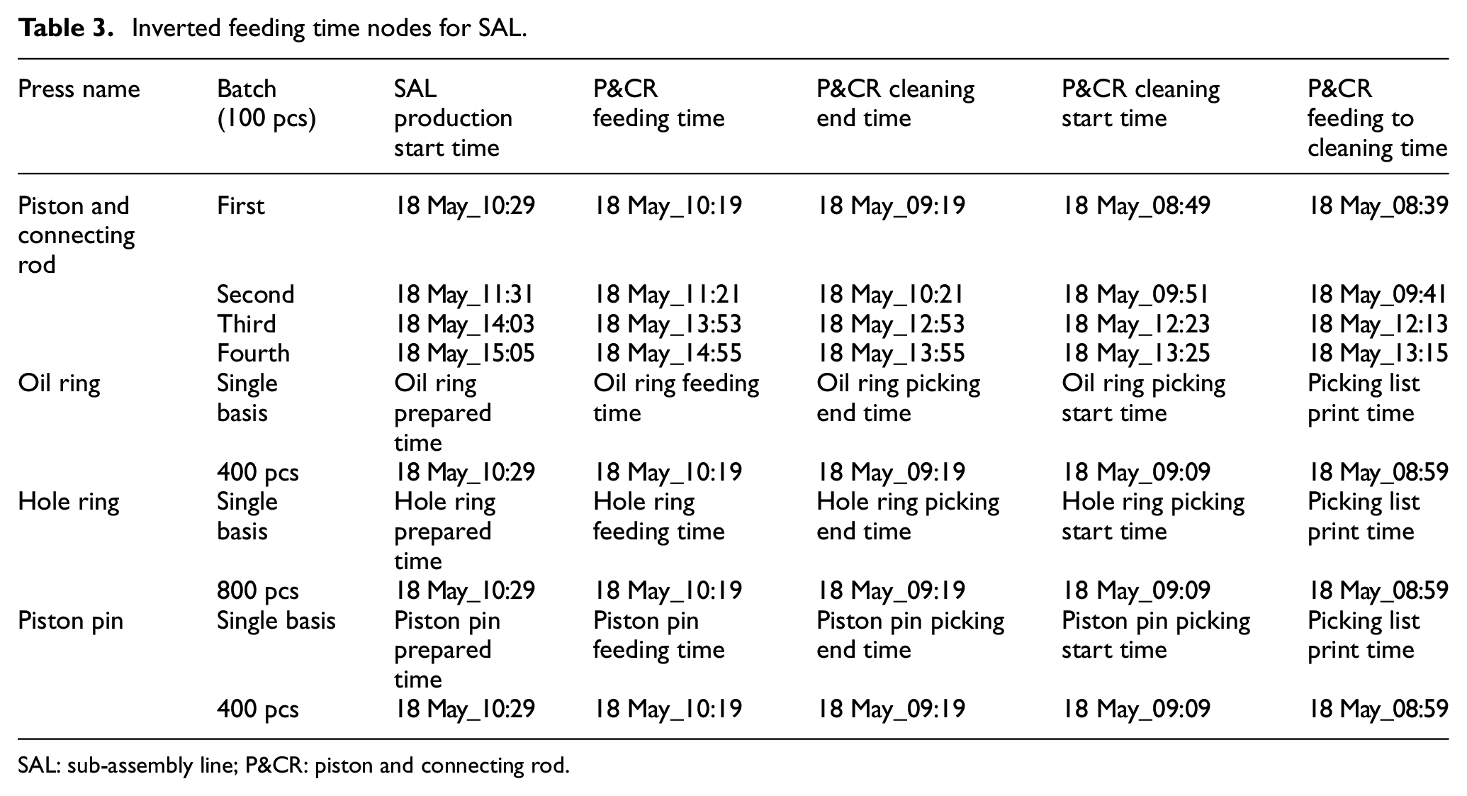
SAL: sub-assembly line; P&CR: piston and connecting rod.
The constraints are given as follows:
SAL production start time: the start time of each PCR production batch on SAL (45 s per piece).
P&CR feeding time: the time when the P&CR is distributed to SAL (10 min before SAL production start time).
P&CR cleaning end time: the end time for cleaning the P&CR and placing with SPS buffer (1 h before feeding time).
P&CR cleaning start time: the start time for cleaning the P&CR (cleaning for 30 min).
P&CR feeding to cleaning time: the time when the P&CR is distributed to cleaning line (10 min in advance).
Oil ring prepared time: the time taken for the preparation of 400 pcs of oil rings (including springs) besides the workstation.
Oil ring feeding time: the time when the oil ring (including spring) is distributed to SAL (10 min before SAL production start time).
Oil ring picking end time: the end time for picking the oil rings (including springs) and placing in the SPS working area (1 h before feeding time).
Oil ring picking start time: the start time for picking the oil rings (including springs) (picking for 10 min).
Picking list print time: the time for printing the oil ring picking list.
Hole ring prepared time: the time required for preparing 800 pcs of hole rings besides the workstation.
Hole ring feeding time: the time when the hole ring is distributed to SAL (10 min before SAL production start time).
Hole ring picking end time: the end time for picking the hole rings and placing in the SPS working area (1 h before feeding time).
Hole ring picking start time: the start time for picking the hole rings (picking for 10 min).
Picking list print time: the time for printing the hole ring picking list.
Piston pin prepared time: the time required for the preparation of 400 pcs of piston pin besides the workstation.
Piston pin feeding time: the time when the piston pin is distributed to SAL (10 min before SAL production start time).
Piston pin picking end time: the end time for picking the piston pin and placing in the SPS working area (1 h before feeding time).
Piston pin picking start time: the start time for picking the piston pin (picking 10 min).
Picking list print time: the time for printing the piston pin picking list.
Feeding time adjustment
As can be seen from the data in Tables 2 and 3, the second batch start time is 11:31, but the first batch completion time is 11:44 on 18 May in the sub-assembly. This indicates that the next batch commences, even though the previous batch is not complete. The inverted production time of the next batch of semi-finished product based on the GAL production demand information will be in conflict with the actual production time. For the semi-finished product, the production start and end times for each batch must be analyzed one by one. If conflicts exist, adjustments should be made based on equation (4) to determine a reasonable operation time. The conflict with respect to the data in Tables 2 and 3 is adjusted. The adjusted time series and batch feeding time nodes are displayed in Tables 4 and 5.
Adjusted production time node for PCRA.
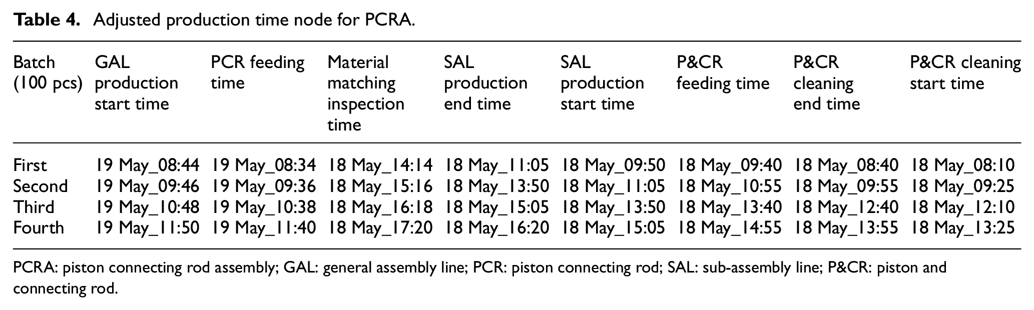
PCRA: piston connecting rod assembly; GAL: general assembly line; PCR: piston connecting rod; SAL: sub-assembly line; P&CR: piston and connecting rod.
Adjusted feeding time node for SAL.
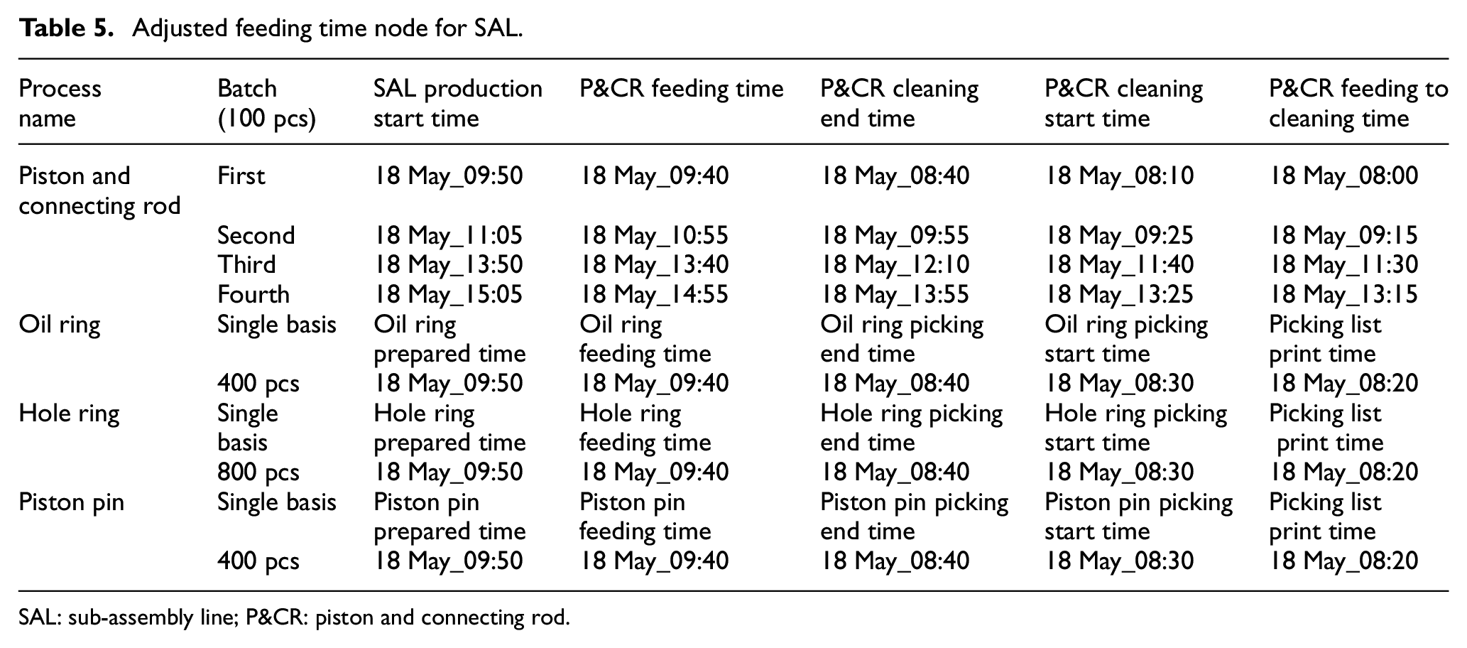
SAL: sub-assembly line; P&CR: piston and connecting rod.
Generation of material distribution TZ table
Based on the logistics operation and production TZ, the quantitative distribution intervals for discrete manufacturing systems can be calculated using the logistics configuration and the feeding time nodes. Furthermore, the material distribution TZ table for the GAL and SAL can be generated to determine accurate time nodes for the feeding operation, material picking operation, reloading operation, supplier arrival, and so on. Using the data from Tables 4 and 5, the material distribution TZ table with 10 batches is generated from workstation number (WN) 14–28, as displayed in Table 6.
Material distribution TZ table.
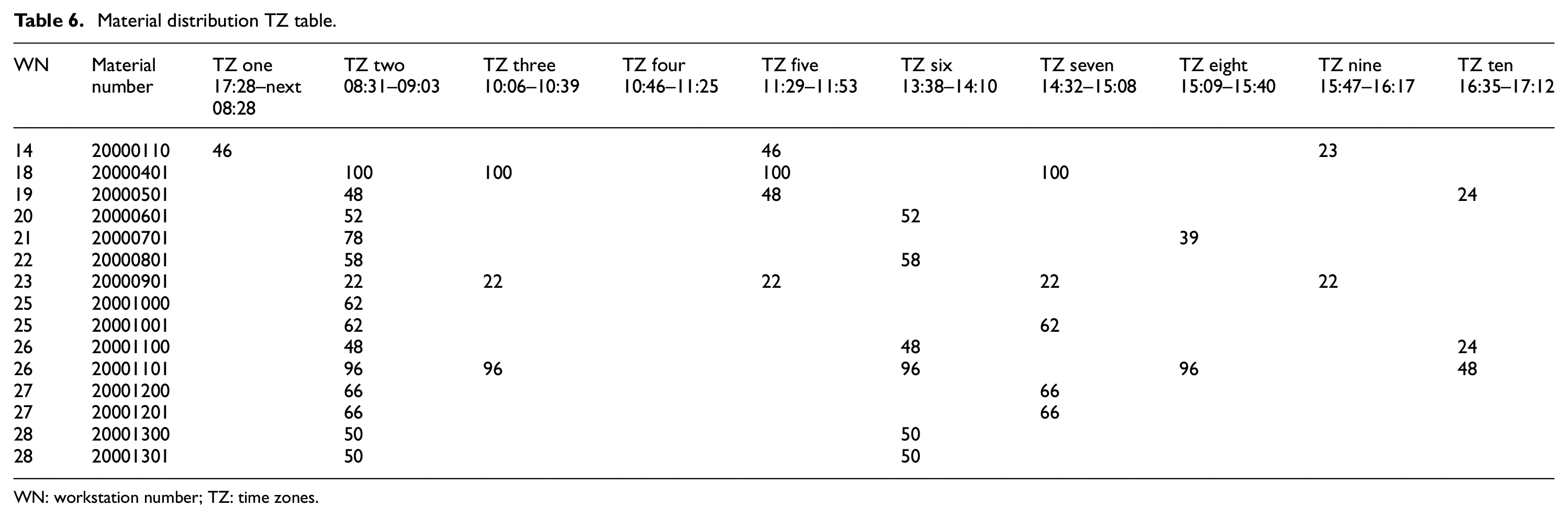
WN: workstation number; TZ: time zones.
Conclusion
By means of the reverse chronological order, a novel material distribution method for assembly lines has been proposed in this study. A case study involving the production data in engine builders indicates the effectiveness of the proposed method. The main contributions can be summarized as follows:
The developed distribution solution with remedies resolves the bulk production time conflict.
Based on the method of system modeling, the active material configuration model has been explored to accurately quantify the material distribution time and intervals, which makes the production work in an organized manner from supply to distribution.
Footnotes
Declaration of conflicting interests
The author(s) declared no potential conflicts of interest with respect to the research, authorship, and/or publication of this article.
Funding
The author(s) disclosed receipt of the following financial support for the research, authorship, and/or publication of this article: This work was supported by the Guangxi Key Laboratory of Manufacturing System & Advanced Manufacturing Technology, College of Mechanical Engineering, Guangxi University, Nanning, 530000, China.