
Abstract
Mg-based metal matrix composites reinforced with nanoparticles are promising biomaterials due to their biocompatibility and high hardness and because they are local and systemic toxicity free. Nano-metal matrix composites are considered to be hard-to-machine materials due to the high strength and high abrasiveness of the reinforcing nanoparticles. In this article, the micro-drilling mechanisms of Mg-based metal matrix composites reinforced with different volume fraction of SiO2 nanoparticles (0.5, 1.0, 1.5, 2.0 vol.%) were investigated experimentally. Results obtained were also compared with pure Mg. First, it was found that the volume fraction and drilling parameters played an important role in the chip formation mechanism. Second, the influence of drilling parameters on hole surface morphology and cutting force were studied, in which both the rotation speed and feedrate affected the surface morphology, and the main factor affecting cutting force was found to be the feedrate. Furthermore, the formation of burrs was investigated. The height of the burr could be reduced by using small feedrate and low rotation speed. Finally, the size effect of micro-drilling was studied. The variation of surface roughness and cutting force of pure Mg and Mg-based metal matrix composites had three changing trends with the uncut chip thickness. The minimum chip thickness of Mg/SiO2 metal matrix composites was determined to be 1.1 μm.
Keywords
Introduction
Magnesium (Mg), as the sixth abundant element in the earth, has the density of 1.74 g/cm3, which is 35% and 77% lighter than aluminum and steel, respectively. 1 At the same time, Mg has excellent biocompatibility and local or systemic toxicity free and high hardness.2,3 Therefore, as a potential alternative biomaterial, Mg has attracted extensive research in the last decade. However, the ductility and poor wear resistance and corrosion resistance of Mg at room temperature greatly limit its potential application. 4 In order to improve the mechanical properties and overcome these limitations, metal matrix composites (MMCs) are fabricated by dispersing stable and low-volume fractional nanoparticles within the matrix to achieve strengthening effect. Silica (SiO2) is composed of two of the most abundant elements (oxygen and silicon) in the earth, which is chemically inert with high hardness and melting point. 5 SiO2 has also been widely used in clinical and biomedical fields, and its potential as a structural material is gradually being utilized by the scientific community. Regarding the biomedical applications, Parande et al. 6 synthesized Mg-(0.5, 1.0 and 2.0 vol.%) SiO2 nanocomposites using hybrid microwave-assisted powder metallurgy. It was observed that the hardness and other properties gradually increased with the addition of SiO2 nanoparticles. Thus, the preparation and material properties of Mg/SiO2 MMCs have been studied and fruitful results have been achieved. However, as a hard-to-process material, its processing properties have not been revealed.
In terms of machining, MMCs with nanoparticles are relatively new composites whose properties are improved by combining the toughness and ductility of the metal matrix phase with the hardness and strength of the reinforcing phase, which make them become hard-to-machine materials. 7 There are two main processing methods for MMCs, namely non-traditional cutting methods and traditional cutting methods. The non-conventional machining technology include electro-discharge machining (EDM), laser cutting, electro-chemical, electrochemical discharge and abrasive waterjet cutting.8,9 The main problem observed within various non-traditional methods is inaccurate surface quality or size. Therefore it seems that traditional methods will continue to be used for situations requiring precise part geometry or good surface finish at the current level of development. 10 In the traditional machining, the researchers mainly studied the influence of varying machining parameters on the surface morphology and tool wear of MMCs. Cheung et al. 11 reported that in circumstances where the reinforcing fibers or particles are pulled from the workpiece during machining of MMCs, the surface finish may deteriorate. Ciftci et al. 12 tested various cutting speeds with fixed feedrate and cut depth of 0.12 mm/rev and 1 mm, respectively in the turning of MMCs. Many studies13,14 have shown that reducing the cutting speed would reduce tool wear when machining MMCs. Vibu Nanthan et al. 15 found that the cutting speed is the main factor affecting the cutting force and tool wear mechanism. Radhika et al. 16 concluded that feedrate has the greatest effect on surface roughness when machining MMCs using analysis of variance (ANOVA). Boswell et al. 17 found that the feedrate is the main factor affecting the surface roughness.
The research on the microfabrication properties of MMCs is the key to medical applications. In the study of micromachining of MMCs, Teng et al. 18 have studied the influence of cutting parameters on the cutting force and surface morphology in micromachining of Mg-based MMCs reinforced with two types of nano-sized particles, namely, titanium and titanium diboride. Liu et al. 19 conducted micro-milling experiments on MMCs reinforced with SiC particles and found that increasing the volume parameters of nano-reinforced fillers can increase the yield strength and fracture strength of MMCs, thereby increasing the cutting force. In addition, the presence of nanoparticles affects the formation of chips, and the cutting force profile is not as smooth as pure Mg.
Mg/SiO2 MMCs have attracted more and more attention as important biomaterials in the future. In the application process, drilling is inevitable, and the drilling process can better reflect the processing properties of materials, so drilling is chosen as the research object. In order to reveal the cutting performance of Mg-based MMCs with different volume fraction of SiO2 nanoparticles (0.5, 1.0, 1.5, 2.0 vol.%), micro-drilling experiments were carried out. In the experiment, the influences of different cutting parameters on the cutting force, burr formation and surface roughness of the hole were analyzed. The chip formation mechanism under the effect of different volume fractions were analyzed. Finally, the size effect of Mg-based MMCs was obtained through surface roughness and cutting force measurements. The experiment results provide a comprehensive understanding on the micro-drilling characteristics of Mg-based MMCs reinforced with different volume fractions of SiO2 nanoparticles.
Experimental setup
In this study, five samples including one pure Mg and four Mg-based MMCs reinforced with different volume fraction of SiO2 nanoparticles (0.5, 1.0, 1.5, 2.0 vol.%) were prepared. Pure Mg powder having a purity of ≥ 98.5% and a size ranging from 60 to 300 μm was used as a base material. SiO2 nanoparticle of purity 99.5% with a size ranging from 10 to 20 nm (Sigma-Aldrich, USA) were used as reinforcement. Mg-based MMCs reinforced with SiO2 nanoparticles were synthesized using the powder metallurgy technology assisted by hybrid microwave sintering. Pure Mg powder and SiO2 nanoparticles were mixed with 200 r/min for one hour in a RETSCH PM-400 mechanical alloying machine (Haan, Germany) after weighing. Billets with 40 mm long and 35 mm diameter were obtained by uniaxial cold pressing of a powder mixture at a pressure of 50 tons. The billet was then heated to 640 °C at 2.45 GHz, 900 W Sharp microwave oven. Cylindrical rods with diameter of 8 mm were extruded by 150 T hydraulic press at a die temperature of 350 °C with an extrusion ratio of 20.25:1. The detailed preparation process has been recorded in the publication. 6 The workpiece was milled into a cuboid shape with dimensions of 60 mm × 7 mm × 4 mm, as shown in Figure 1(a).
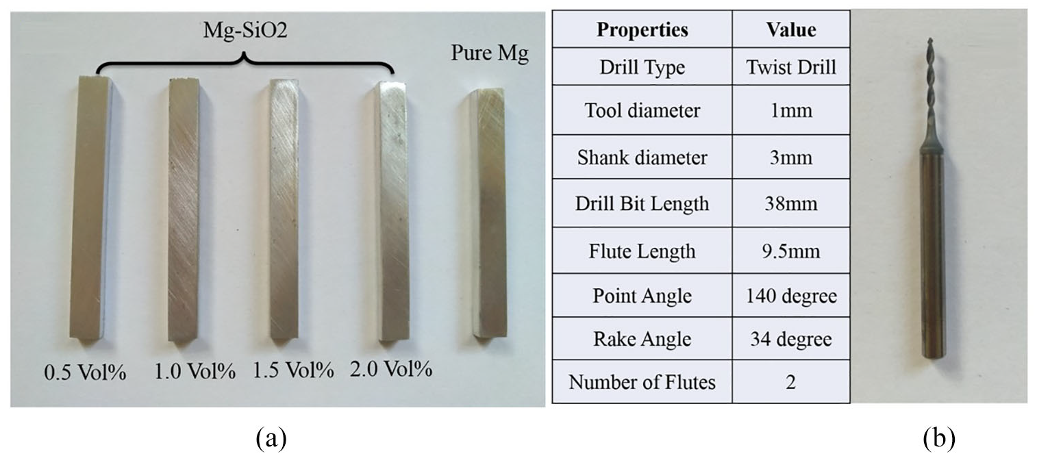
Workpiece samples (a) and micro drill properties (b).
Uncoated tungsten carbide micro twist drill with diameter of 1.0 mm and shank diameter of 3 mm were utilized, shown in Figure 1(b). The geometry of all the new tools used in the experiment was examined by a scanning electron microscope (SEM, Hitachi TM3030) before drilling. The cutting edge radius was estimated to be 1.3 μm by SEM. One new drill was used for each workpiece to ensure the accuracy of the measurement. A desktop precision machine tool (Nanowave MTS5R) equipped with a high-speed spindle in the range of 5000–80,000 r/min was used for the machining experiment. It features high feedrate, meanwhile maintaining movement of X, Y, Z axis by minimum of 0.1 μm, which has been reported in the publication. 18
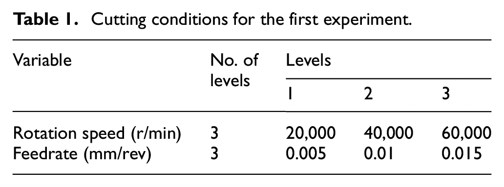
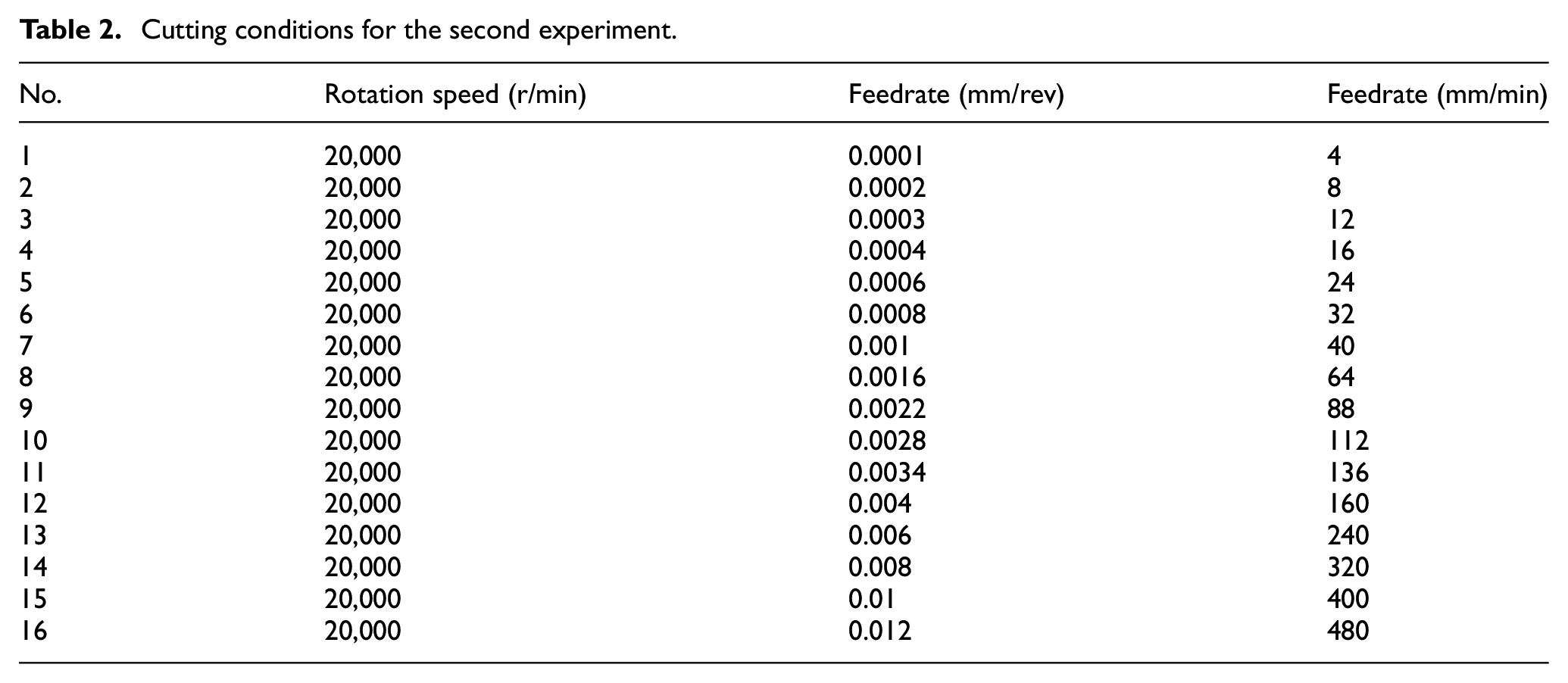
Brand new micro drill was used for each sample in order to obtain the accuracy of experimental results. The first experiment used a full factorial design approach in which two controlled quantitative factors were used, namely rotation speed and feedrate, as listed in Table 1. The effects of cutting parameters on cutting force and surface roughness were investigated based on drilling with nine different cutting conditions. Table 2 shows the cutting conditions for the second experiment, in which the rotation speed is constant and 16 different feedrates are used to study the size effect in micro-drilling. In order to analyze the burr formation and surface topography of drilled hole, each sample was cut along the center line using a milling cutter to reveal the section view of the drilled hole. The drilled holes are through holes with a diameter of 1 mm, a depth of 4 mm and a distance of 2 mm between the holes. An SEM was used to conduct the microstructure analysis. The surface roughness of the machined surface was measured using a SurfTest.
Cutting conditions for the first experiment.
Cutting conditions for the second experiment.
Results and discussion
Chip formation
The study of the chip formation can provide a better understanding of the changing trend of the hole surface morphology. Because of the difference in material structure and machining parameters, the shape and size of chips are different. Generally, chip morphology can be divided into eight categories: 20 (1) powder, (2) fan, (3) needle, (4) short ribbon, (5) long ribbon, (6) very long ribbon, (7) short spiral, (8) long spiral. In this experiment, this classification will be used. Chip formation will be affected by micro-structure, ductility and cutting parameters such as rotation speed and feedrate. Figure 2 illustrates the chip shapes of pure Mg and Mg/SiO2 MMCs (0.5 and 2.0 vol.%) under different cutting parameters.
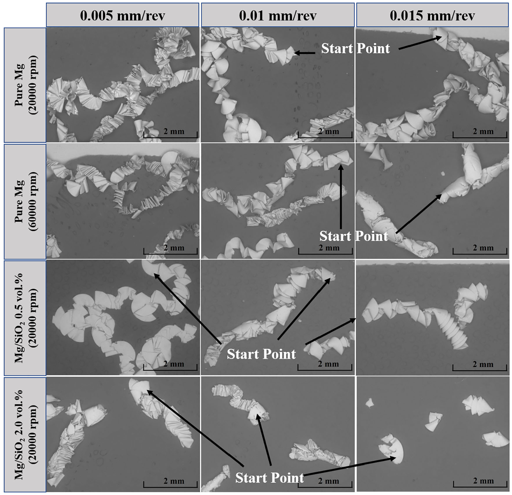
Chips formation of pure Mg and Mg/SiO2 MMCs under different parameters.
In pure Mg, chips are easier to form due to its higher ductility and lower hardness. Obviously, when the rotation speed is 20,000 r/min and the feedrate is 0.005 mm/rev, the contact area between the micro-cutter and the workpiece is the starting point of the chip, which enables chips to be generated continuously as the micro-cutter curls upward. In this case, the pure Mg chip will be long and continuous, showing a long spiral shape, and the chip will be wound on the tool during drilling, which is not conducive to drilling. With the increase in feedrate, the chip thickness will increase, resulting in an increased friction between the chip and the workpiece during the cutting process. This leads to the easy breaking of the chip and the formation of short spiral chips. Figure 2 also shows the difference of chip length when the rotation speed increases from 20,000 to 60,000 r/min. The chip length decreases with the increase in rotation speed along with the morphology changing from long spiral to short spiral at the same feedrate. This can be attributed to the increased heat generated in the cutting process when increasing the cutting speed, which softens pure Mg. At the same time, the chips will rub the surface of the machined holes during the extraction process. The friction force will cause breakage of the chip, thus forming short spiral chips. The chip shape and the changing trend of Mg/SiO2 MMCs 0.5 vol.% are similar to that of pure Mg workpiece, which is due to the low volume fraction of materials and the close material properties with pure Mg. When the volume fraction of SiO2 nanoparticles increases to 2.0%, the chip morphology changes. At low feedrate, short spiral shape type chips are formed. With the increase in feedrate, the chip becomes more discontinuous resulting in segmentation. On the one hand, the increase in SiO2 nanoparticles increases the hardness of the matrix material, 6 on the other hand, super hard nanoparticles act as small chippers, breaking the chips into small pieces. From the surface quality perspective, shorter chips are more advantageous.
Figure 3 shows the SEM micrographs of chip shapes when drilling pure Mg and four types of Mg-based MMCs. It can be observed from Figure 3(a) of the chip micro-morphology in drilling pure Mg that the chip has smooth edge and regular grooves on the chip surface. This is mainly due to the high ductility and low hardness, which increases the blurred material between the tool and chip, resulting in grooves on the inner surface of the chip. With the increase in the SiO2 nanoparticle volume fraction, the chip surface is no longer regular, and a large number of fragments appear (see Figure 3(b) and (c)). The main reason is that the addition of hard SiO2 nanoparticles reduces the ductility of matrix materials leading to brittle chip formation with more debris. At higher nanoparticle volume fraction (1.5% and 2%), a large number of cracks is observed on the chip surface, and the larger the volume fraction, the larger the cracks (see Figure 3(d) and (e)). It is mainly due to the existence of hard particles, which make the chip deformation and stress concentration occur along the shear zone. As a result, the debonding of nanoparticles from the matrix results in cracks and some small voids.
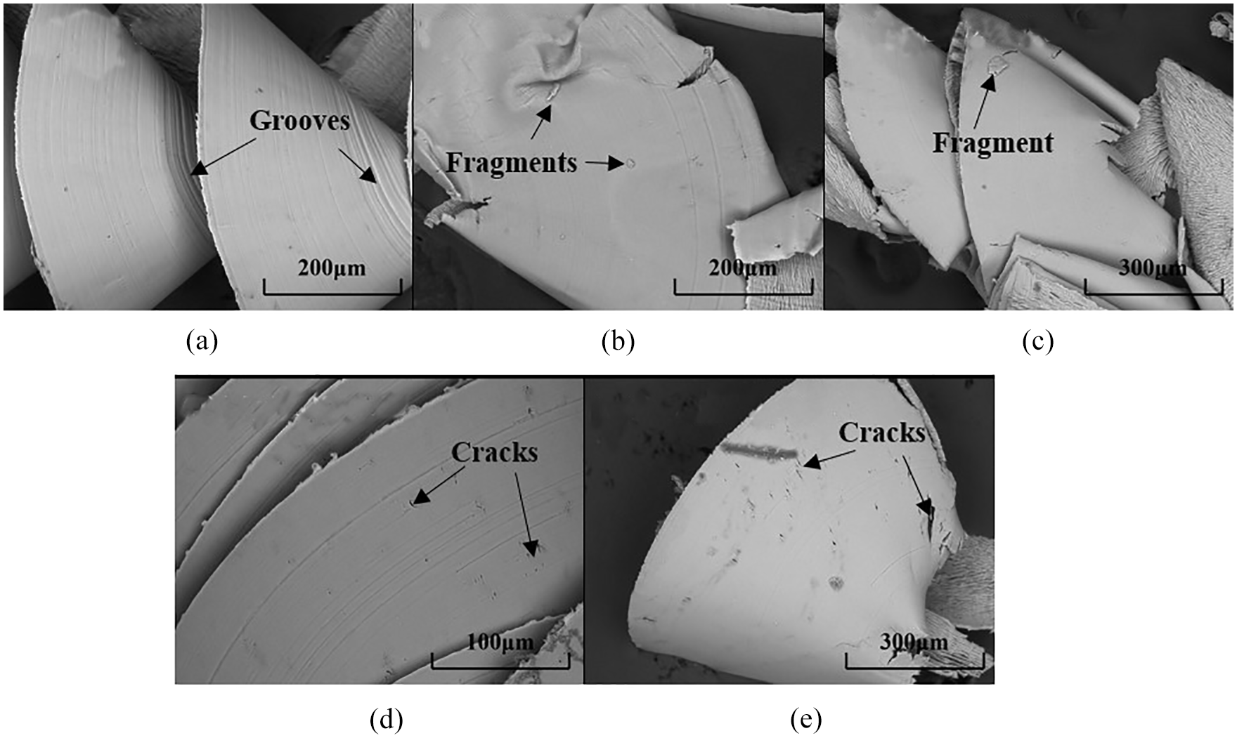
Chips morphology of pure Mg and Mg-based MMCs reinforced with SiO2 nanoparticles. (a) Pure Mg. (b) Mg/SiO2 0.5%. (c) Mg/SiO2 1.0%. (d) Mg/SiO2 1.5%. (e) Mg/SiO2 2.0%.
Surface morphology
In order to study the influence of drilling parameters on the surface roughness, the drilled samples were cut along the central line, and the surface roughness of holes was measured by SurfTest. Three locations, namely the entrance, the middle and the exit of the hole were measured to obtain the average surface roughness. The surface roughness of the entrance, middle and exit of the hole do not change much in the study of drilling Mg/SiO2 MMCs, so the study is limited to the relationship between the average surface roughness of the three locations and the cutting parameters only. Figure 4(a) is the relationship between the average surface roughness of five materials under the effect of various feedrates at a rotation speed of 20,000 r/min. Figure 4(b) is the relationship between the average surface roughness of the hole and the rotation speed at the feedrate of 0.01 mm/rev. It can be seen that the average surface roughness increases with the increase in feedrate and decreases with the increase in the rotation speed, which shows a similar trend with literatures.21,22 At the same rotation speed, the hole surface roughness with lower feedrate is lower, and the surface quality will decrease with the increase in feedrate.
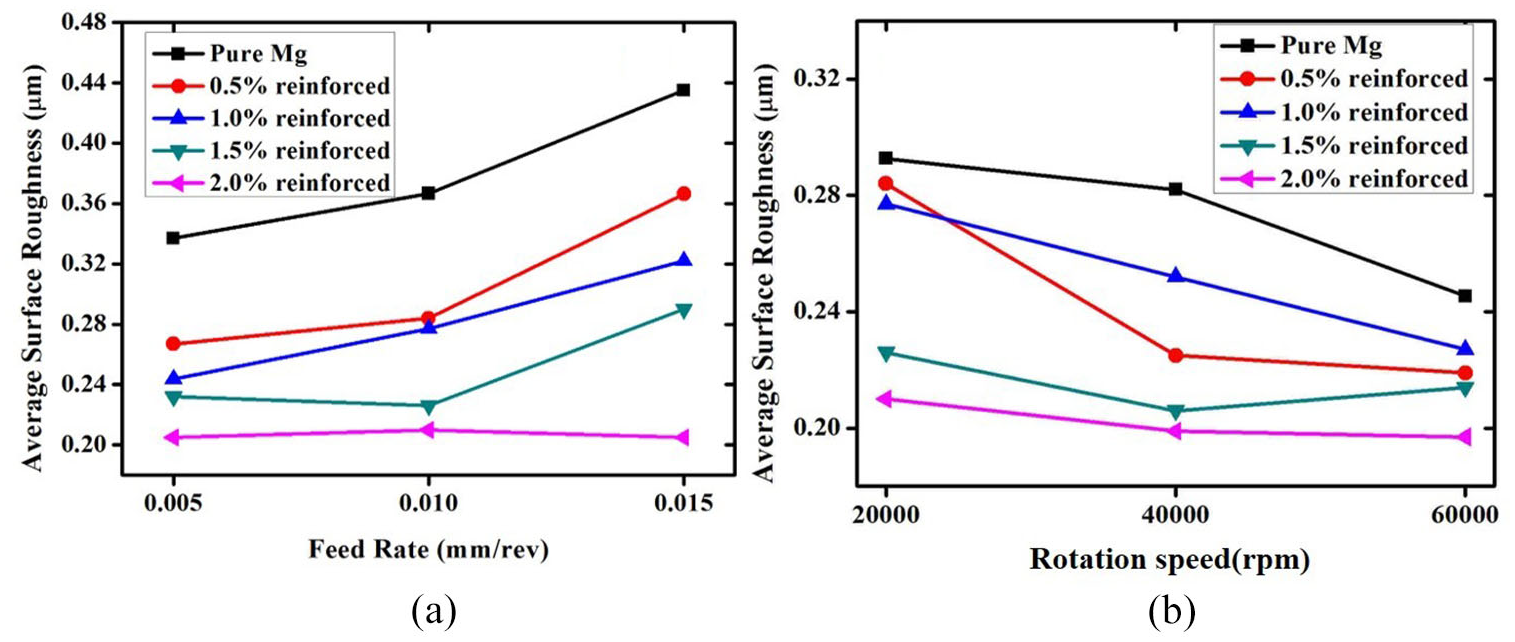
Variation of surface roughness with two cutting parameters (a) 20,000 r/min (b) 0.01 mm/rev.
The surface roughness of pure Mg is the highest compared to that of Mg/SiO2 MMCs under the same cutting parameters, shown in Figure 4. The surface roughness decreases obviously with the increase in the SiO2 fraction. This is due to the fact that pure Mg has the characteristics of soft texture thus experiencing a large plastic deformation during machining process. On the other hand, the chip is longer and hard to discharge, which is easy to cause damage to the surface during the export process. When the volume fraction increases, the hardness of the material increases, and the deformation of the workpiece after cutting is smaller. At the same time, the chip becomes short spiral or powder shape, which is easy to export and causes less damage to the machined surface. When the volume fraction of SiO2 nanoparticles reaches 2.0%, the feedrate makes little effect on the average surface roughness, and shows a weak downward trend with the increase in rotation speed. This trend is directly related to the increased brittleness of materials.
Figure 5 is the SEM micrograph of pure Mg under different cutting parameters. The drilling direction of Figure 5 is from top to bottom, which is explained in this article. The surface morphology of the exit position varies greatly, so Figure 5 shows the surface morphology of the exit position. The obvious material flow along the borehole direction can be seen, which is the evidence of plastic deformation of pure Mg. When the feedrate is small, the heat generated by the cutting action between the tool and the workpiece in the cutting process is extremely easy to soften the pure Mg, which makes the material flow more obvious along with the direction of the tool rotation. With the increase in feedrate, the thickness of material removed increases, resulting in the decrease in heat per unit volume. At this time, the softening phenomenon of Mg decreases, which makes the material flow not obvious, and grooves appear instead. When the feedrate is 0.005 mm/rev and the rotation speed increases from 20,000 to 60,000 r/min, the material flow is more obvious. It is mainly due to the increase in the rotation speed that the heat generated will greatly increase and the rate of softening of Mg will be greater.
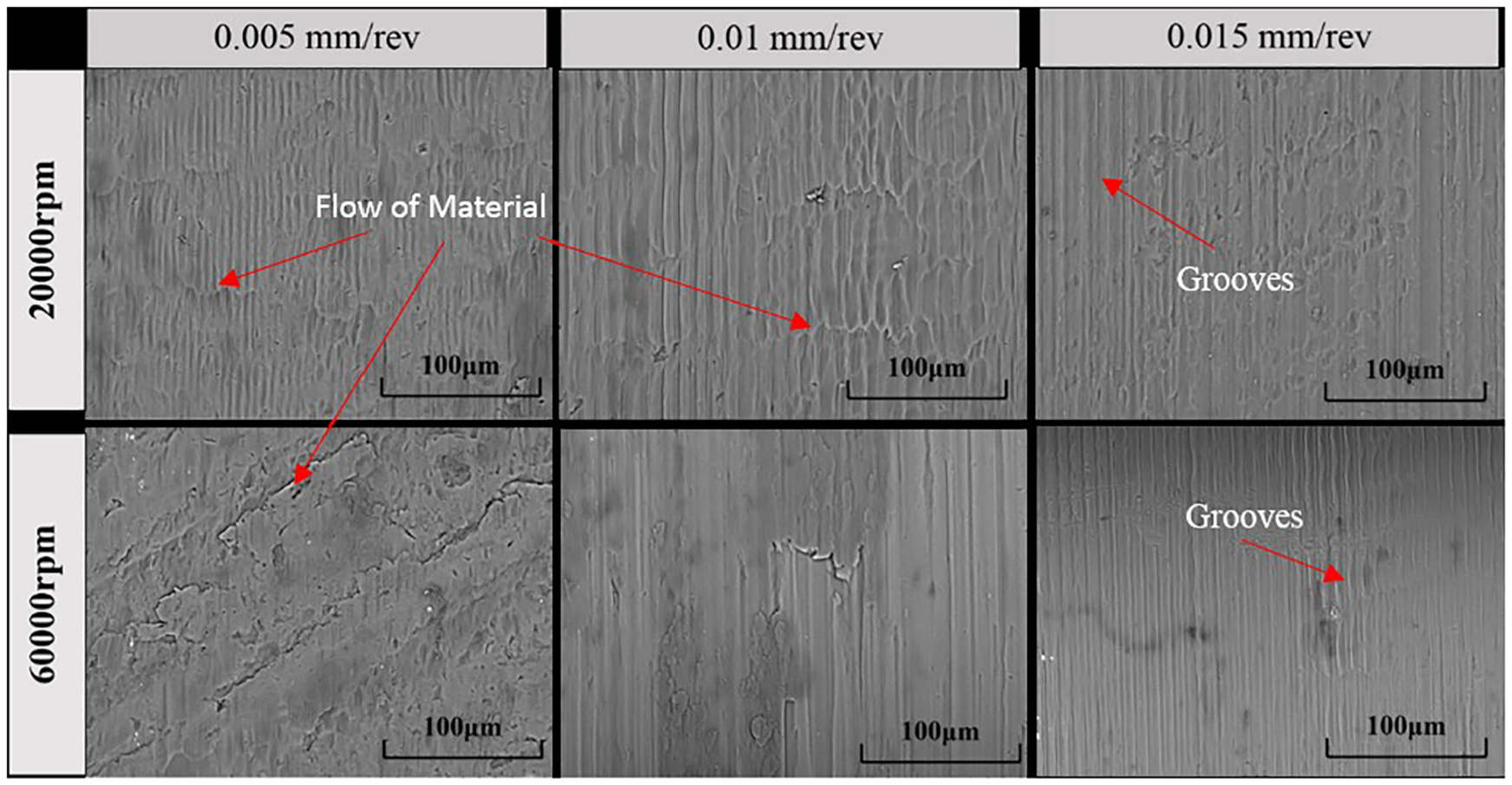
Surface morphology of pure Mg under different cutting parameters.
Figure 6 shows the micro-morphology of Mg/SiO2 MMCs at a rotation speed of 20,000 r/min. When the volume fraction of SiO2 nanoparticle is 0.5%, the surface morphology is similar to that of pure magnesium, which is mainly due to the small volume fraction and the similar properties with pure Mg. When volume fraction increases, the fluidity of the material decreases under the same cutting parameters. The Mg matrix is strengthened and the softer matrix is supported, which increases the hardness and brittleness of the material. Meanwhile, the increase in SiO2 particles limits the ductility of Mg-based MMCs, which directly leads to the transition from plastic fracture to brittle fracture during machining process. When the volume fraction of SiO2 particles is 2.0% and the feedrate is 0.005 mm/rev, defects in the forms of cracks are evident on the inner surface of the micro-drilled. The reason for large cracks generation is the reinforced nano-particles debonding/dislocation at the shearing zone, which leave the small cracks and these cracks generated together finally form the large cracks.
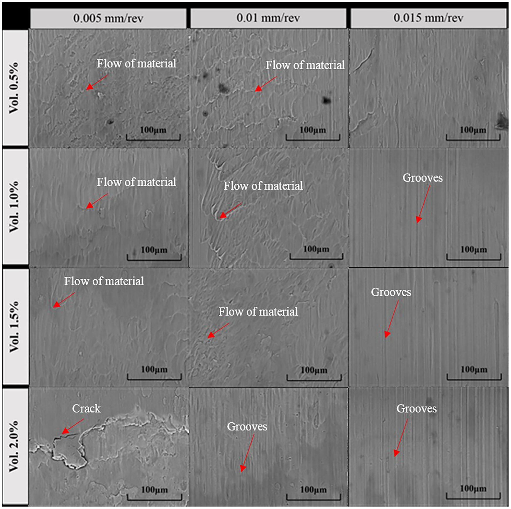
Surface morphology of Mg-based MMCs reinforced with SiO2 nanoparticles at rotation speed of 20,000 r/min.
Burr formation
Burrs occur in most processing processes, which cause a number of problems to the quality and function of products, such as interfering with the assembly of parts or reducing fatigue life. In some cases, deburring of micro-parts is impossible due to brittleness and edge tolerance. Therefore, it is essential to understand the formation of burrs and to predict and reduce burrs in micro-processing. There are three types of burr shapes: Uniform burr, transient burr and crown burr. 23
Rotation speed, feed speed and material properties are the main factors that affect the burr formation in micromachining. The burrs in the entrance are much smaller than that in exit, so the exit burrs are analyzed. Figure 7 is the burr morphology of pure Mg and Mg/SiO2 MMCs in the exit holes at different feedrates. Figure 8 shows burr height of pure Mg and Mg/SiO2 MMCs under different cutting parameters. As can be seen from Figure 7, the burrs of pure Mg can be classified as uniform burrs, and the enlarged local burrs in Figure 7 show that the surface of pure Mg burrs is smooth, which is attributed to the high plastic deformation and ductility of Mg. Combining with Figure 8(a), it can be concluded that the burr height increases with the increase in feedrate and rotation speed, which is in agreement with the results of previous studies.23,24 When the rotation speed is 20,000 r/min and the feedrate is 0.005 mm/rev, the burr height is the smallest and easy to break. With the increase in feedrate and rotation speed, the softening effect of Mg increases. The plastic deformation plays more dominant contribution to the formation of longer burrs. At the rotation speed of 60,000 r/min, the burr height increases greatly.
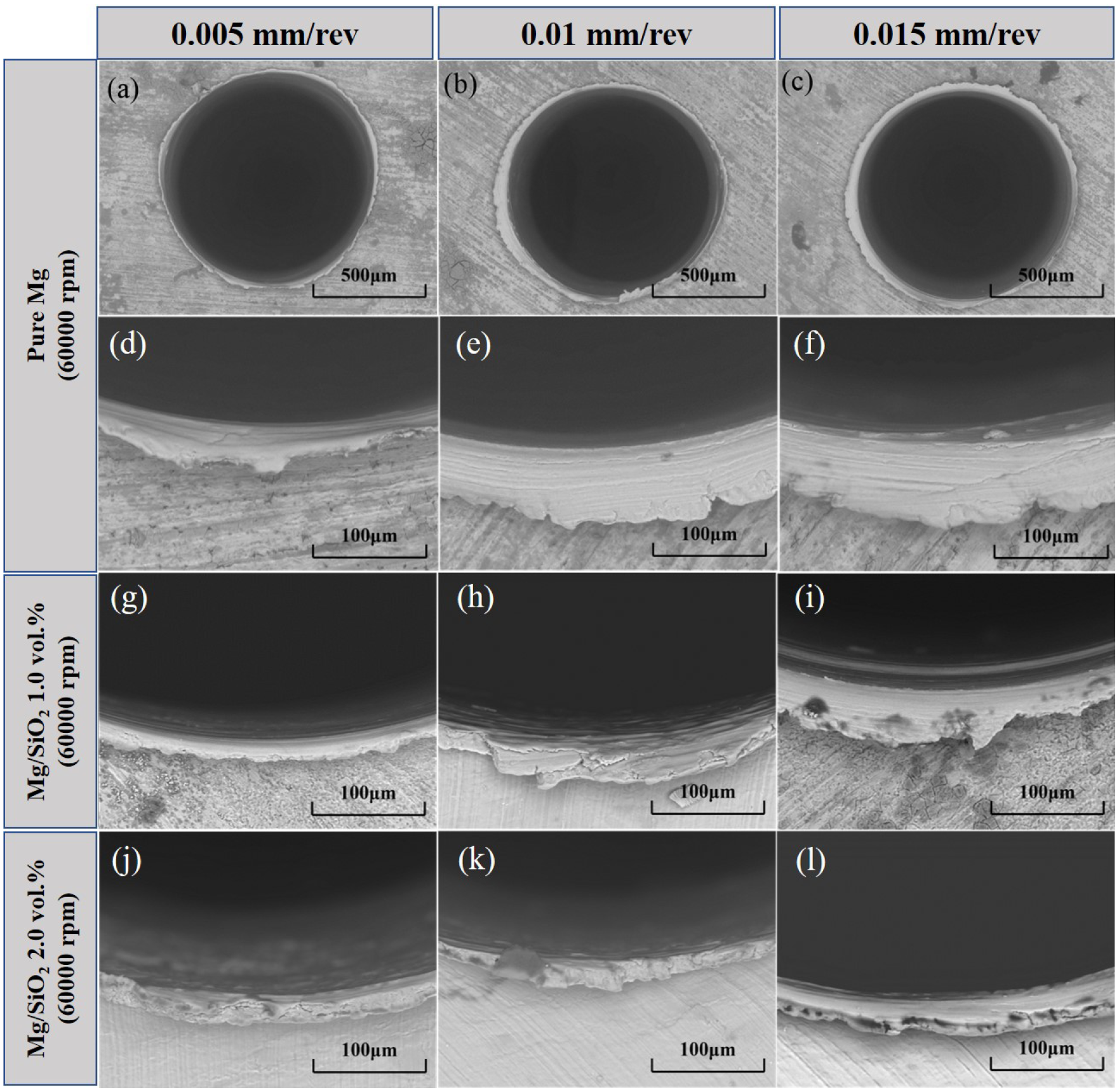
Burr (exit hole) of Pure Mg and Mg/SiO2 MMCs under different cutting parameters.
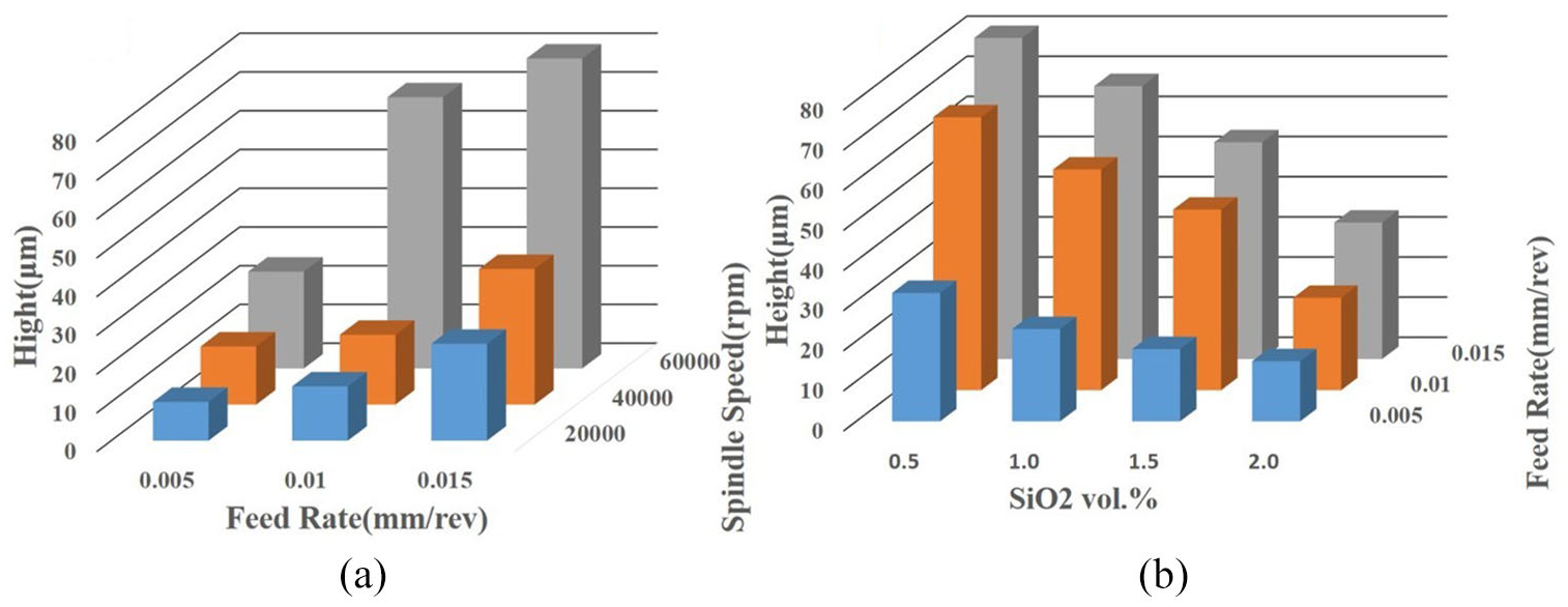
Burr height of pure Mg (a) and Mg/SiO2 MMCs (b) under different cutting parameters.
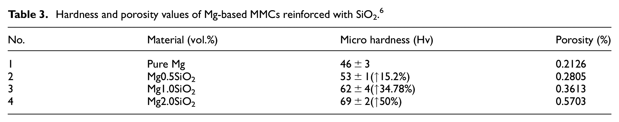
Figure 7(g)–(l) show the variation of burr height of Mg/SiO2 MMCs with different volume fractions at the rotation speed of 60,000 r/min. The burr height of pure Mg is similar to that of MMCs with a volume fraction of 0.5%, which can be attributed to the content of SiO2 particles being small and the material properties are equal to that of pure Mg. When the volume fraction of SiO2 nanoparticles increases to 2.0%, the burr height decreases sharply. This can be mainly explained by the fact that the hardness of the material increases by 50% compared with that of pure Mg, as shown in Table 3. This results in a decreased ductility of the material. Figure 8(b) is the burr morphology of Mg-based MMCs reinforced with SiO2 nanoparticles when the rotation speed is 60,000 r/min. Therefore, smaller feedrate and rotation speed should be adopted in order to obtain smaller burr height.
Hardness and porosity values of Mg-based MMCs reinforced with SiO2. 6
Size effect
Macromachining and micromachining are similar in kinematics, but there are many basic differences as well. When the uncut chip thickness becomes comparable to the radius of cutting edge, the size effect becomes the dominant factor affecting the cutting process. In this section, the effect of size effect on cutting is studied based on analyzing the cutting force and surface morphology.
Figure 9(a) indicates the variation of cutting force with the uncut chip thickness. By observing the cutting force profile, the cutting forces of five different materials are found to have similar changing trends and all have experienced three cutting regions. The first area (I) is the area where the uncut chip thickness is less than 0.3 μm. In this area, the uncut chip thickness is much less than the critical chip thickness. The materials are plowed off by the elastic deformation without chip formation. With the increase in the uncut chip thickness, the cutting force increases greatly, which is attributed to the elastic deformation of the material and the restoration of the deformed material to its initial position. Therefore, the uneven distribution of stress is caused by the interaction between workpiece and cutting tool. The second area (II) is the transition zone where the thickness of uncut chips is between 0.7 and 1.7 μm, in which the feed per tooth is close to the critical chip thickness. The uncut chip thickness is close to the tool edge radius. At the same time, the plastic and elastic deformation of the workpiece will occur simultaneously in this region, resulting in a significant reduction of the cutting force between the workpiece and the cutting tool. The third area (III) is the cutting force obtained where the uncut chip thickness is greater than 1.7 μm. The feed per tooth in this area is greater than the critical chip thickness. Continuous chips occur through shearing under the plastic deformation. Therefore, the fact that cutting force increases with the increase in the feed is explained in the section “Surface morphology.” The increase in SiO2 nanoparticles will directly affect the change of cutting force as shown in the local enlargement figure A. In the first area (I), the cutting force increases with the increase in SiO2 nanoparticles, and the cutting force is the largest when the content of SiO2 nanoparticles is 1.0%.
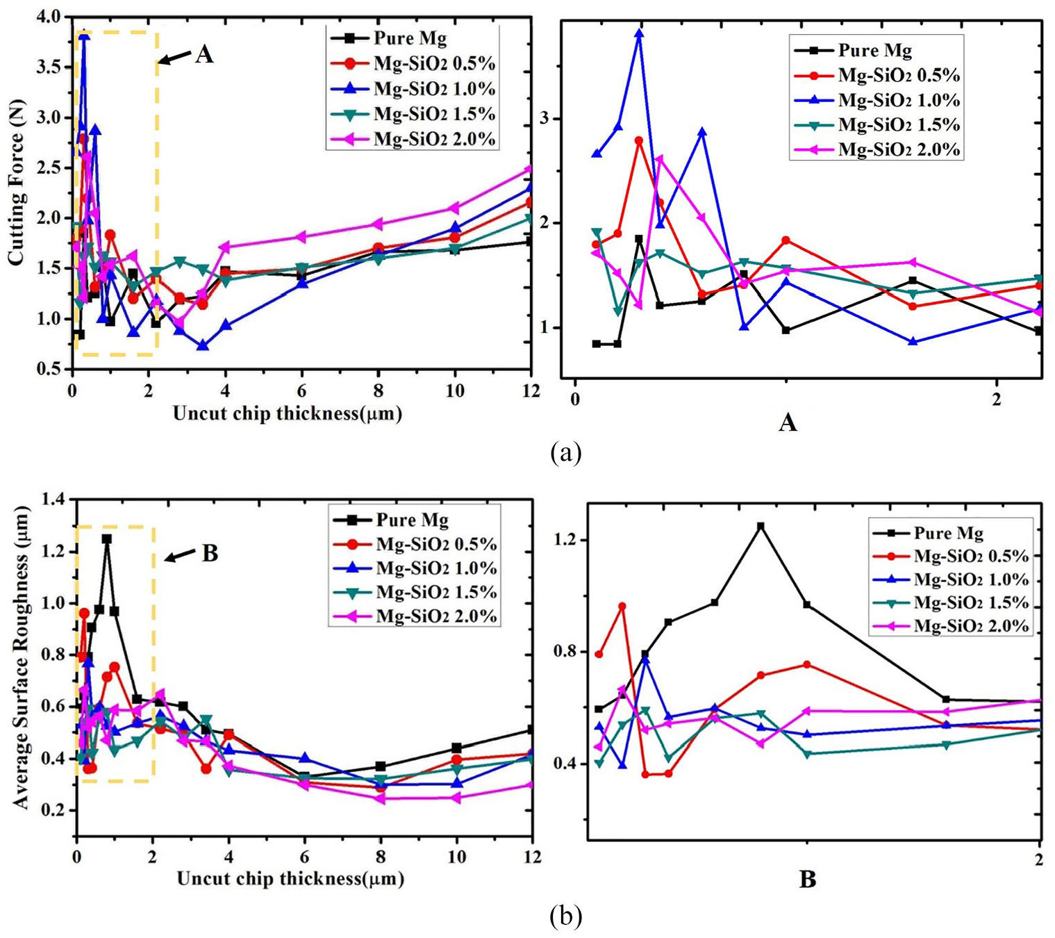
Cutting force (a) and surface roughness (b) versus uncut chip thickness.
A close relationship can be found between the surface roughness of the hole and the cutting force. Figure 9(b) is a variation curve between the mean surface roughness and the uncut chip thickness. Figures 10 and 11 illustrate the surface morphologies of pure Mg and Mg/SiO2 MMCs under different uncut chip thickness. The average surface roughness also experienced three trends. The first trend is that the average surface roughness increases with the increase in the uncut chip thickness. It can be seen that a severe peeling phenomenon occurs on the surface of the workpiece due to the plowing phenomenon when the thickness of uncut chips is 0.2 μm. The increase in volume fraction increases the hardness, leading to a more serious peeling phenomenon. When the uncut chip thickness is 0.8 μm, elastic deformation and plastic deformation coexist to form irregularly distributed grooves on the machined surface, which is the main cause of further increase in average surface roughness. Deeper grooves are produced and the average roughness also reaches a maximum due to pure Mg being softer and its plastic deformation is also larger than the other four Mg/SiO2 MMCs, shown in Figure 11. The second trend is that the average surface roughness decreases as the uncut chip thickness increases. In this region, irregular grooves gradually disappear from the surface of the hole and a significant material flow occurs, which causes a decrease in the average surface roughness. The third variation is that the surface roughness increases with the increase in the thickness of the uncut chip. It can be seen that regular grooves found on the surface are produced by the plastic cutting of the tool.
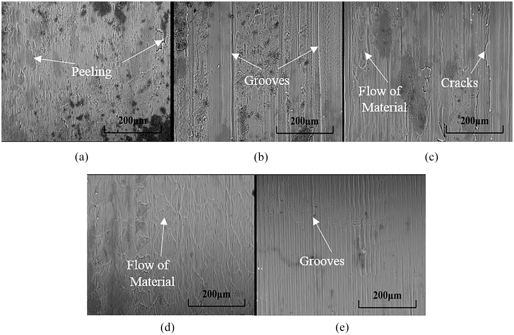
Surface morphology of pure Mg under different uncut chip thickness (a) 0.2 μm (b) 0.8 μm (c) 1.6 μm (d) 3.4 μm(e) 12 μm.
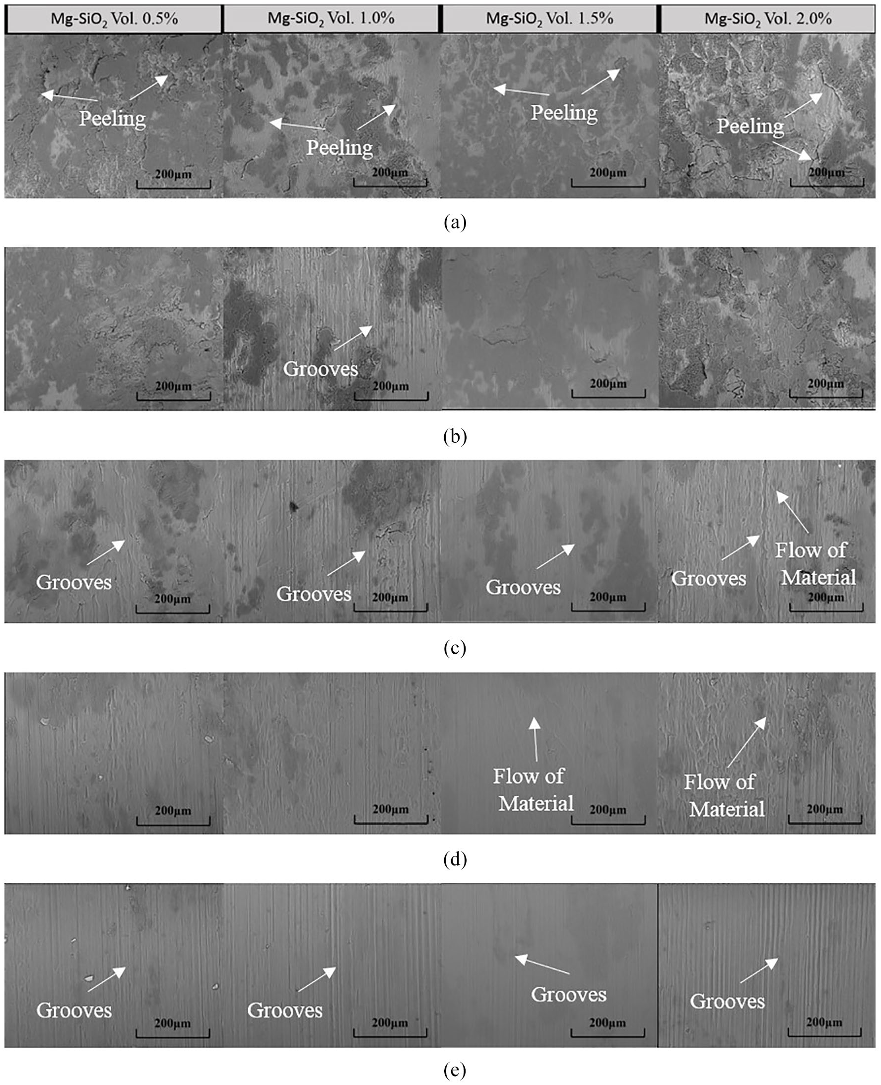
Surface morphology of Mg-based MMCs reinforced with SiO2 nanoparticles under different uncut chip thickness (a) 0.2 μm (b) 0.8 μm(c) 1.6 μm (d) 3.4 μm (e) 12 μm.
Higher cutting force and worse machined surface quality are obtained at the small feed per tooth ranging from 0.05 to 1.7 μm/tooth in pure Mg indicating a strong size effect. When the content of SiO2 nanoparticles is different, the ranges of size effect are different. When the content of SiO2 is 0.5%, the size effect range is 0.03 to 1.1 μm/tooth. When the content of SiO2 is 1.0% and 1.5%, the size effect range is 0.03 to 0.8 μm/tooth. When the content of SiO2 is 2.0%, the size effect range is 0.03 to 0.6 μm/tooth. This is related to the increase in the hardness of materials with the increase in SiO2 particles. Considering the influence of cutting force and surface roughness, it can be concluded that the minimum cutting thickness of pure Mg and Mg/SiO2 MMCs should be 1.7 μm and 1.1 μm, respectively.
Conclusion
The micromachining properties of pure Mg and four Mg-based MMCs reinforced with different volume fractions of SiO2 nanoparticles were studied by micro-drilling. First, the burr formation and surface morphology of the five materials were studied. The influencing factors of the machined surface roughness were analyzed. In addition, the influencing factors of the burr were also proposed. Finally, the size effect of micro-drilling was revealed by analyzing the cutting force and surface morphology. The minimum cutting thickness is obtained. This study can draw the following conclusions:
The chips obtained from machining pure Mg are in spiral shape. The shape of the chips change from long spiral to short spiral as the feedrate and rotation speed increase. An increase in the volume fraction of SiO2 nanoparticles would result in an increase in the brittleness of the Mg-based MMCs material. The cracks produced on the chip surface with increase in rotation speed and feedrate, causes the chips morphologies to change from short spiral to powder.
The Mg-based MMCs become brittle as the volume fraction increases. The increase in the rotation speed causes an increase in the fluidity of the material, which in turn causes a decrease in surface roughness. The increase in feedrate results in the transition from a surface where the material flows significantly to a surface containing regular grooves, which causes an increase in surface roughness.
The chip morphology obtained from machining pure Mg and Mg-based MMCs reinforced with SiO2 nanoparticles are all uniform burrs. Smaller feedrate and rotation speed are used in micro-drilling to achieve smaller burr heights.
In the size effect study, the surface roughness and cutting force of the five materials showed three trends with the uncut chip thickness. The minimum cutting thickness of pure Mg and Mg/SiO2 MMCs should be 1.7 μm and 1.1 μm, respectively. It is not recommended to perform micro-drilling below the minimum chip thickness per tooth.
Footnotes
Declaration of conflicting interests
The author(s) declared no potential conflicts of interest with respect to the research, authorship, and/or publication of this article.
Funding
The author(s) disclosed receipt of the following financial support for the research, authorship, and/or publication of this article: This project is supported by National Natural Science Foundation of China (Grant No. 51805246) and Natural Science Foundation of Jiangsu Province (Grant No.BK20180704).