
Abstract
Grinding of large or ultralarge components to achieve stringent quality is always challenging in China’s manufacturing industry, for example, roller for steel strip production. Compared with transverse cylindrical grinding, roller grinding requires high-precision multiaxis motion. In addition, with the increasing demand for process efficiency, the in-process measurement and process compensation become necessary for higher process reliability and productivity. This article presents the state-of-the-art and emerging technology in China’s roller grinding, which includes heavy-duty grinding machine optimization, high-performance tooling design, in-process geometrical accuracy compensation, in-site machine vision for gloss defect, and intelligent process parameter optimization strategy. Therefore, this article will shed light on the development trend of the enabling technology toward intelligent roller grinding with higher accuracy, dexterity, and efficiency.
Introduction
As the world’s largest steel manufacturer and consumer, China is undertaking the industrial upgrade toward higher quality and efficiency as well as lower cost and pollution. During 2015–2020, there is about 100–150 million tons steel production capacity needs to be transferred and upgraded in China, 1 which requires to build more than 300 high-end rolling production lines and a large number of auxiliary equipment. In the steel manufacturing industry, roller grinding machine is one of the critical equipment serving to prepare high-quality rollers for either hot rolling or cold rolling. The classification of rolling process and roller is given in Figure 1(a), and Figure 1 (b) shows a typical roller with continuously variable crown (CVC) profile that is widely used in a modern hot rolling process. 2 Therefore, the roller grinding machine (Figure 1(c)) must possess the capability of high-precision multiaxis motion under heavy load and long-time service. Meanwhile, to adapt to the demand for the industrial upgrade, the modern roller grinding machine must be developed toward higher efficiency, intelligence, and user-friendliness, which requires the integration of advanced grinding technology, machine vision technology, and artificial intelligence in to the roller grinding machine.
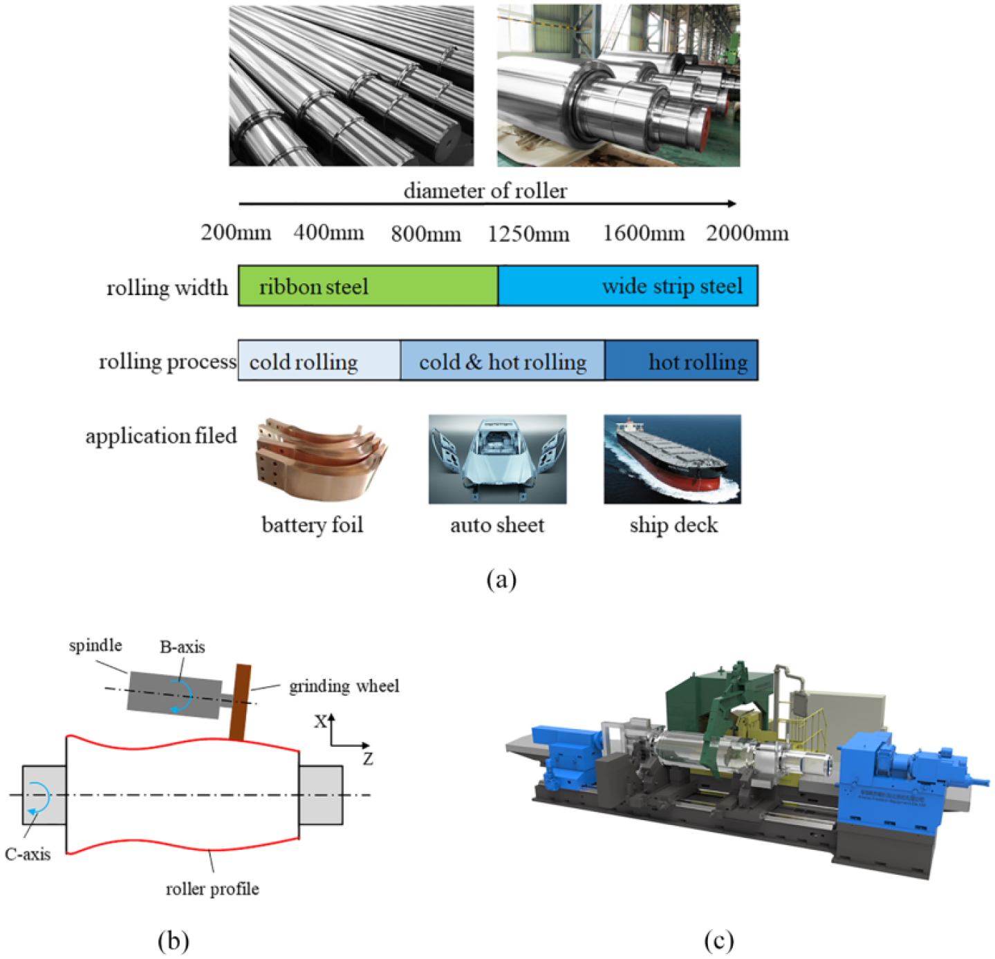
(a) Classification of rolling process and roller; (b) roller grinding process; and (c) roller grinding machine.
Unlike conventional transverse cylindrical grinding,3–6 the roller grinding possesses more special quality requirements, for example, roller profile accuracy and visual gloss defect. The roller profile shown in Figure 1(b) can be expressed as z = f(x), where f represents the fitting function, x and z are the displacements along the X and Z axes, respectively, and the range of the highest power of z is from 5 to 12. In terms of the roller profile accuracy, a curve at fifth power and up to 12th power must be achieved at 0.002 mm across the whole roller length. As of the visual gloss defect, which cannot be characterized by surface roughness Ra or Sa, it has to be examined by bared eyes of experienced engineers. Therefore, apart from the dimensional, roundness accuracy, and surface roughness, the roller grinding process must accomplish roller profile accuracy and visual gloss defect requirement simultaneously.
In this article, the critical enabling roller grinding technology is introduced toward higher stability, efficiency, accuracy, and intelligence, including: (1) the grinding machine platform, high-speed spindle development for high-speed grinding stability; (2) the novel approach for high-performance cubic boron nitride (CBN) grinding development toward high-efficiency roller grinding; 3) in-process measurement and compensation for roller profile generation; (4) machine vision technology development for high-glossiness roller surface measurement and defect diagnosis; and (5) intelligent process generation strategy development for multiple process outcomes. Finally, toward the emerging industrial need toward higher flexibility and intelligence, the outlook for intelligent roller grinding machine and production line is presented.
High-speed roller grinding spindle and platform
During the roller grinding process, the spindle power and grinding velocity can reach 100 kW and 80 m/s or even higher, respectively. In addition, the profile accuracy, usually at fifth power and up to 12th power, must be achieved at 0.002 mm across the whole roller length. Under these extreme conditions and quality requirements, how to develop high-speed roller grinding spindle and platform is a primary problem.
High-speed spindle with lubricant temperature regulation
In the case of roller grinding, the power and velocity of spindle exceed the values of general milling by an order of magnitude, 7 and the thermal effects 8 of spindle are an important aspect related to the changes of surface integrity of roller and lifetime of the grinding wheel. The bearing temperature of spindle is the main factor for thermal effect, which will further determine the clearance of bearing. In order to guarantee the oil film rigidity of spindle bearing, the quadratic curve of oil chamber is redesigned, and the profile slot grinding is used to manufacture the oil chamber to ensure the accuracy, as shown in Figure 2(a). A temperature monitoring system of bearing is established by using a built-in temperature sensor, which is shown in Figure 2 (b), and based on this feedback mechanism, the temperature of spindle bearing can be real-time controlled through lubricant temperature compensation. Figure 2(c) describes the structure of the invented high-speed spindle, 9 which maintains the temperature fluctuation of spindle bearing within 5% at the spindle power of 100 kW. The stiffness and accuracy of spindle during high-speed grinding process achieve 900 N/μm and 1 μm through this design, respectively, which are beneficial for the grinding quality.
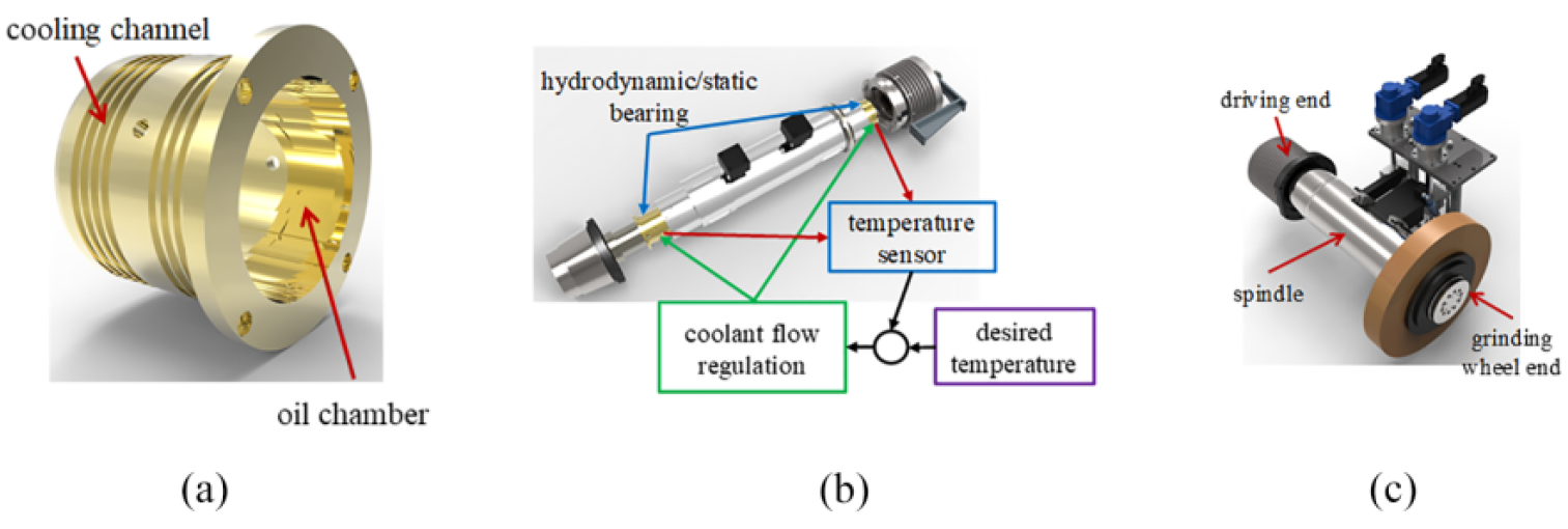
High-speed spindle with lubricant temperature regulation: (a) Spindle bearing; (b) temperature sensing and monitoring system; and (c) 3D model of the spindle.
Guideway, eccentric sleeve and B-axis
Besides the high-speed spindle, the guideway, eccentric sleeve and B-axis are essential elements for a roller grinding machine as well. For the guideway servicing under heavy-load condition, the stiffness and position-independent behavior must be guaranteed. A novel unloading guideway with hydraulic system is designed, as shown in Figure 3(a), to replace the conventional hydrostatic guideway and overcome the shortages, such as uneven load, unstable oil pressure, and inconsistent oil film thickness. The repeated positioning accuracy of grinding carriage can achieve less than 0.005 mm/overall length, which meets the accuracy requirement. A rotary hydrostatic eccentric sleeve with high rigidity and accuracy is invented based on lever principle, which is driven by a servo motor via a ball screw, as shown in Figure 3(b). Due to the exclusion of additional transmission components, the transmission error is eliminated. With this special eccentric sleeve, the feed sensitivity of grinding wheel reaches 0.0001 mm, which realizes the precision movement with higher resolution for roller profile generation. Furthermore, a B-axis with variable angle is developed by designing a rotating axis system. The system utilizes an additional rotating axis to actuate the grinding wheel spindle to swing within a small angle range (±1°) in the horizontal plane perpendicular to roller profile at all times, as shown in Figure 3(c). 9 Based on the additional B-axis motion, the highest 12th power curve is realized to complete the grinding of the complex roller profile.
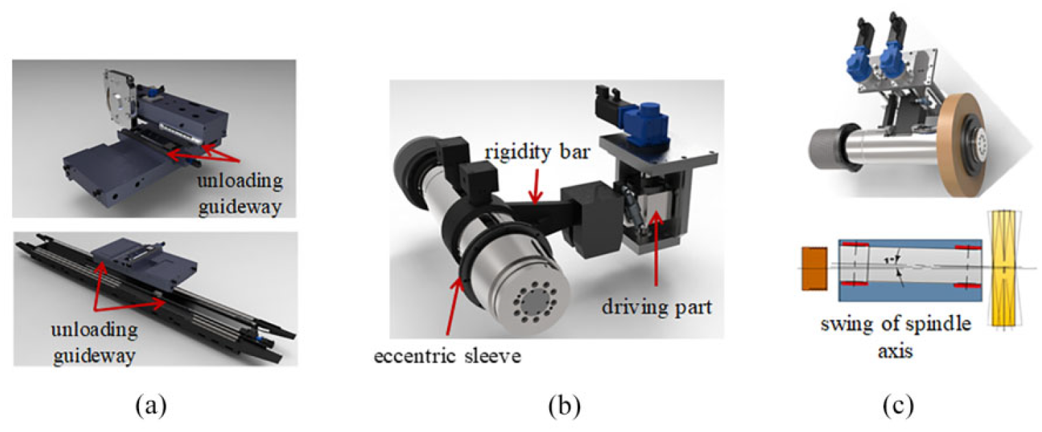
Essential structural elements of the roller grinding machine: (a) unloading guideway; (b) eccentric sleeve; and (c) B-axis with variable angle.
Performance optimization of grinding machine through simulation
The simulation-based method is frequently used in the design phase of grinding machines to improve system behavior, such as static, dynamic stiffness, and thermal performance. After the structure design, the simulation model of the roller grinding machine under different speed and load domains is established by using finite element (FE) analysis. 10 Combining with the modal characteristics and heat transfer characteristics during the roller grinding process, the analysis and optimization of machine tool bed, headstock, and the related joint surfaces are completed, as shown in Figure 4. Based on these works, the system rigidity and movement stability of the roller grinding machine are greatly improved under high-speed and heavy-load conditions.
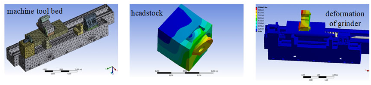
The analysis and optimization of roller grinding machine.
High-performance CBN wheel development for roller grinding
The design of high performance for CBN grinding wheels requires the fine-tuning of wheel recipe under various process load conditions. The critical practices for roller grinding wheel design covers: (1) the selection of proper CBN specification among current hundreds of commercialized CBN; (2) bond material and sintering process optimization for expected wheel hardness and wheel strength; and (3) digitalized wheel benchmark technology for prompt performance characterization.
Abrasive failure mechanism for high-speed and heavy-load conditions
Although claimed as a single crystal, current commercial CBN grains are not always perfect, and contain point defect, dislocation, and amorphous phase. By slicing a sample piece from one CBN grain (Figure 5(a) and (b)), Figure 5(c) indicates that the existence of defect under transmission electron microscope (TEM) observation. And CBN grains from different vendors exhibit different defect contents. Therefore, apart from the CBN grain shape, the internal crystal defect is a vital factor that must be considered for high-performance grinding wheel design. Through the crack development simulation based on the G-criteria fracture energy theory,11,12 Figure 6(a) demonstrates how crack propagates through each phase inside the CBN grain from 60 to 100 m/s. The static indentation test on CBN grain provides the mechanical response under various load conditions, and hmax and hf in Figure 6(c) represent the maximum indention depth and the corresponding indention depth after rebounding. By the development of high-speed single grain scratch test platform (Figure 6(b) and (c)), an individual CBN grain is brazed onto a tool holder tip and applied to cut into the specified workpiece for about 100 m. Therefore, the grain static fracture as well as wear mode–load correlation can be established to characterize the transition of grain wear to grain fracture. The correlation of the fracture under increasing speed and load condition provides the direct discrimination criteria for CBN grain performance. And utilizing Figure 6(d), the CBN grain optimal selection can be realized for expecting grinding load condition.
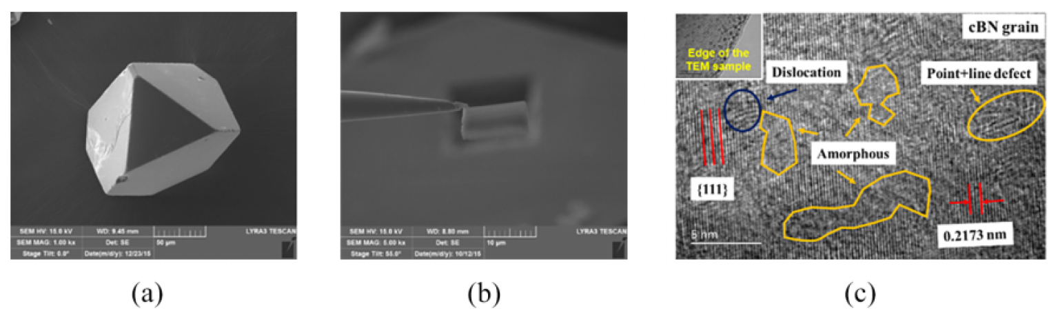
Defect characterization of CBN crystal: (a) scanning electron microscope (SEM) of CBN grain; (b) slice after iron beam thinning; and (c) TEM observation.
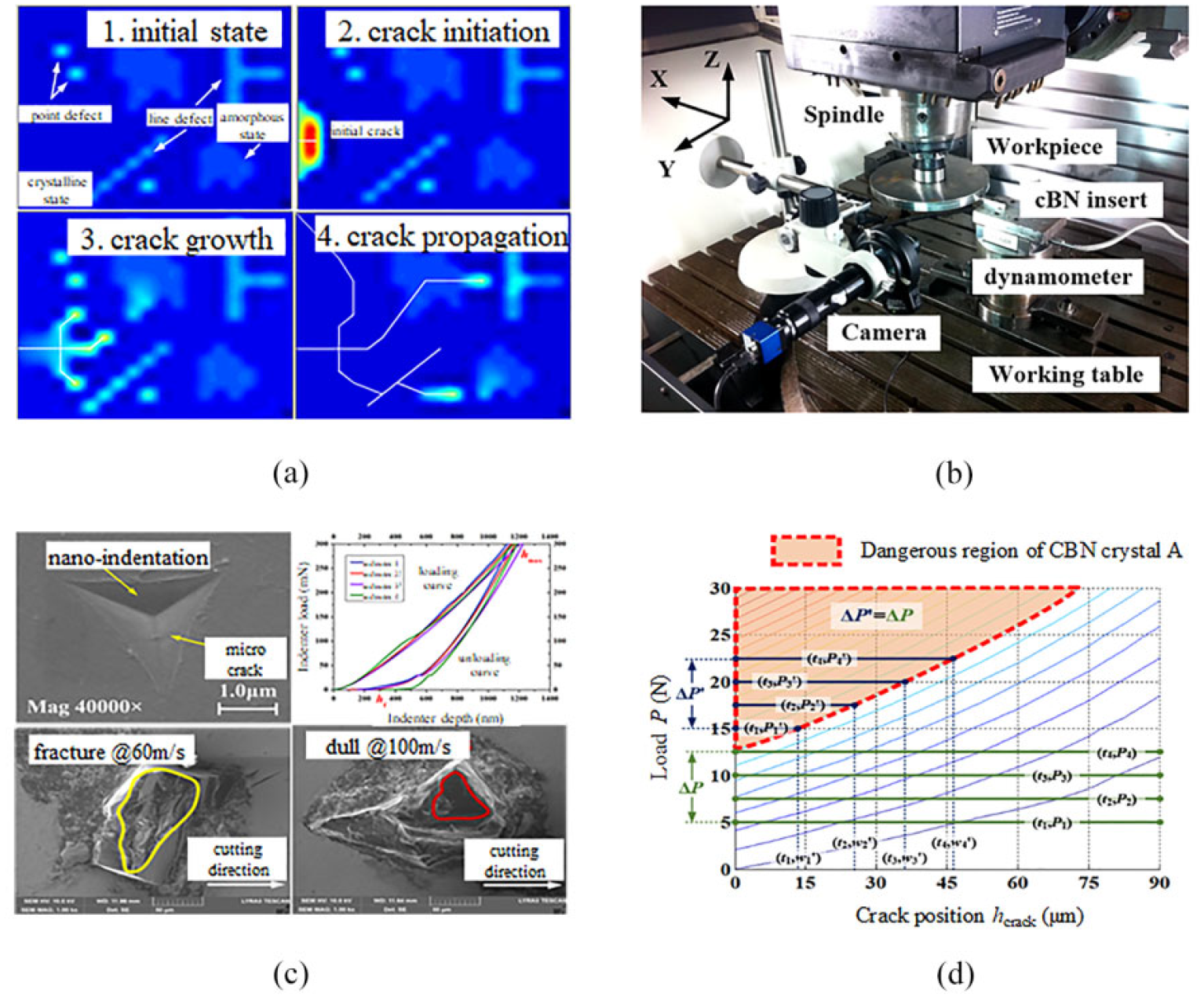
CBN failure simulation, test, and performance characterization technology: (a) failure simulation; (b) test platform; (c) test results; and (d) performance characterization.
Simulation of wheel strength
During roller grinding, the wheel experiences high temperature and heavy load. Thus, the establishment of the wheel strength simulation model corresponding to different process conditions is necessary for optimal wheel design. By utilizing pseudorandom grinding wheel simulation, Figure 7(a) shows the wheel strength distribution to identify the failure prone zone.13,14 Then, the optimal bond selection can be carried out through comparing its thermal strength behavior with the grinding load distribution. Therefore, the grinding wheel recipe can be proactively designed to minimize the wheel damage and performance degradation in grinding. By combining the abrasive and bond selection technologies, the developed CBN grinding wheel is capable of satisfying a wide range of surface roughness and quality requirements. The material removal rate can reach up to 120 kg/h, and the grinding time reduces from 20 to 12 min when grinding a roller of Φ1250 mm × 2050 mm, as shown in Figure 7(b).
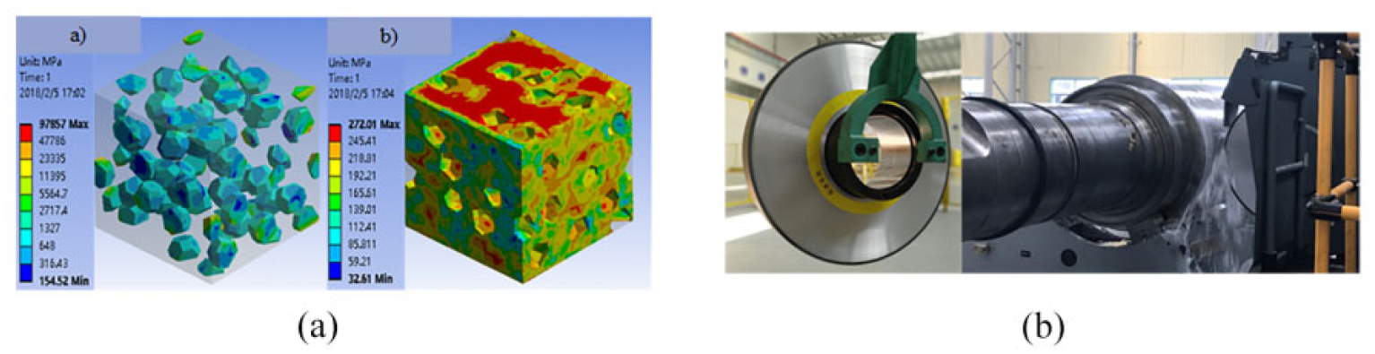
(a) Strength simulation for the grinding wheel and (b) application of the grinding wheel.
Intelligent enabling technologies
Besides the high-speed and high-precision roller grinding machine, intelligent enabling technologies are essential to support the steel industrial upgrade toward higher quality and efficiency as well as lower cost and pollution. This section describes related technologies, including adaptive landing and automatic rotating system, in-process profile error measurement and compensation, and surface defect detection and identification through machine vision.
Adaptive landing and automatic rotating system
When loading a large roller with bearing box onto the grinding machine, the position accuracy will be affected due to impact. Moreover, the modern roller grinding requires the accomplishment of grinding process without disassembling the bearing box, thus to extend the bearing life. To avoid the interference of bearing box and grinding wheel, an adaptive landing and automatic rotating system must be developed. By designing the hydraulic support device with built-in pressure sensor, the contact status of roller and support device can be determined within a range from 50 to 250 mm, as shown in Figure 8(a). 9 The moving trajectory of the support device can be adaptively matched with the motion of the crane to reduce the impact. As of the bearing box rotating system, a support cylinder is applied to drive the rotation of bearing box, as shown in Figure 8(b). 9 Thus, under the condition without human interference, a large roller with bearing box can be turned 90° in a safe, reliable, and efficient manner.
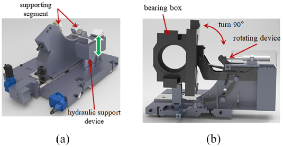
(a) Adaptive landing device and (b) automatic rotating device.
In-process profile error measurement and compensation
The modern roller grinding requires in-process profile error measurement and compensation, thus to guarantee the profile accuracy and production efficiency. In order to accomplish the in-process profile error measurement, a turnover-type measurement device is designed combining with the three-point measuring structure and the actuating cylinder, as exhibited in Figure 9(a). 9 By utilizing the measurement device, Figure 9(b) shows the measured roller profile error of head, middle, and tail ends with an accuracy of 0.001 mm. Meanwhile, the numerical control (NC) system calculates the compensation value according to the measurement result and then modifies the grinding parameters. After compensation, the roller profile accuracy is capable of reaching up to 0.002 mm, as shown in Figure 9(c).
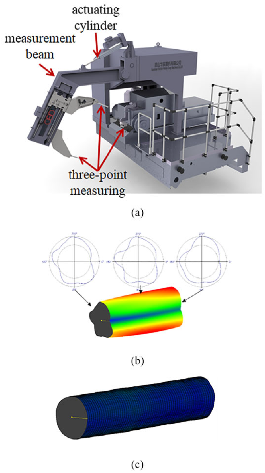
(a) In-process profile error measurement device; (b) measurement result; and (c) compensation result.
Surface defect detection and identification through machine vision
Visual gloss defect (Figure 10(a)) is a special quality requirement of roller grinding, and traditional manual roller surface detection is inefficient and depends on the skill of engineers. In order to overcome the shortages of manual roller surface detection, based on the machine vision, a roller surface in-process imaging system is developed,15,16 which consists of a lighting module, imaging module, image acquisition and control module, adjusting mechanism, and cleaning device, as shown in Figure 10(b). By using the maximum entropy threshold segmentation algorithm and the feature extraction algorithm through deep convolutional neural network, the automatic segmentation and intelligent identification of the roller surface defect are realized (Figure 10(c)). The detection and identification results of two typical surface defects are given in Figure 10(d), including speckle and short scratch defects, and a large number of experiments indicate that the identification efficiency can achieve 95%.
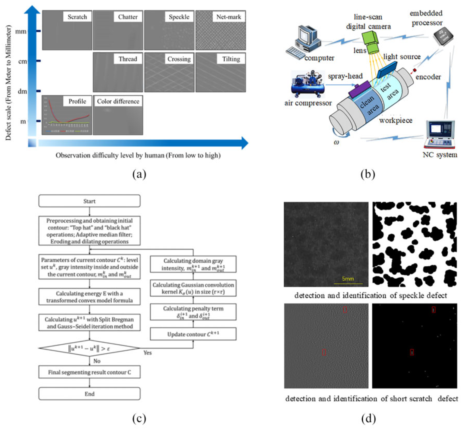
(a) Classification of visual gloss defect; (b) the roller surface in-process imaging system; (c) flowchart of the automatic segmentation and intelligent identification of the roller surface defect; and (d) detection and identification results of two typical surface defects.
Digitalized grinding precise benchmark technology
In order to benchmark the grinding performance and identify the potential root causes of process instability during grinding, an in-process data acquisition system is developed for the roller grinding machine. The system consists of the measurement in terms of spindle power, support run-out error, vibration of grinding carriage, and lubricant temperature. Figure 11(a) shows the practical application of the system, which provides the fundamental information for fault diagnosis in the time domain. Figure 11(b) shows the spindle power as the function of time during the grinding process. By utilizing the system, the correlation of roller run-out and spindle power can by identified as indicated in Figure 12(a), which is caused by the support run-out error as in Figure 12(b). By reducing the support run-out error in Figure 12(c), the grinding power fluctuation is reduced while decreasing the run-out error of the roller.
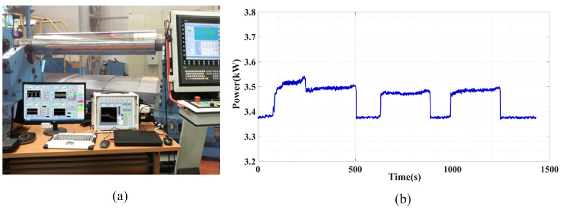
(a) The application of the data acquisition system and (b) the measurement of spindle power.
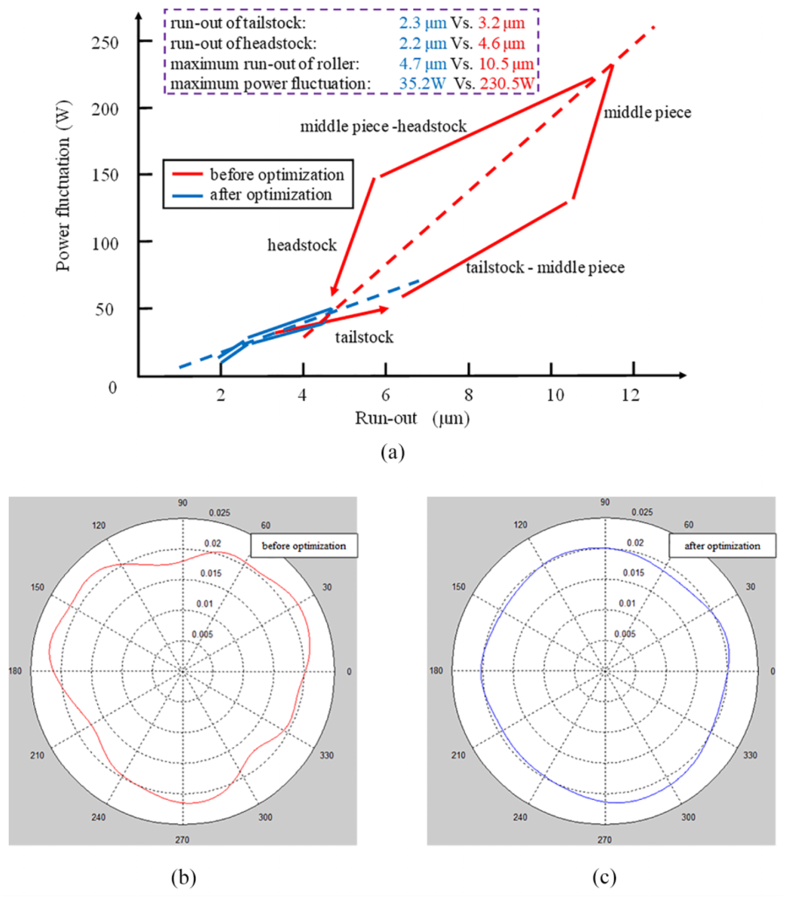
(a) The correlation of roller run-out and spindle power; (b) support run-out error before optimization; and (c) support run-out error after optimization.
Multipass process parameter optimization strategy
The roller grinding process generally contains multiple passes, including rough, semifinishing, finishing, and spark-out grinding, and each stage consists of more than one pass and several grind parameters, for example, grinding wheel speed, grinding depth, roller speed, and traverse feed rate. In addition, the roller quality requirement includes surface roughness, cylindrical error, profile accuracy, and so on. Therefore, the multipass process parameter optimization strategy must possess the capabilities of dealing with multiple objectives, parameters, and constraints. 17 Based on the swarm intelligent optimization algorithm (Figure 13(a)), the framework of the multipass grinding process optimization strategy is described in Figure 13(b). 18 The hybrid particle swarm optimization (PSO) is developed with the integration of the dynamic inertial weight algorithm and adaptive density grid algorithm. With the integration of the two algorithms, the global searching ability and efficiency of basic PSO are improved. The surface roughness evolution model is built based on the response surface methodology and as one of the optimization objective. The grinding efficiency (represented by material removal rate) is another optimization objective. The machine-tool capability is regarded as the constraints in the procedure of iteration.
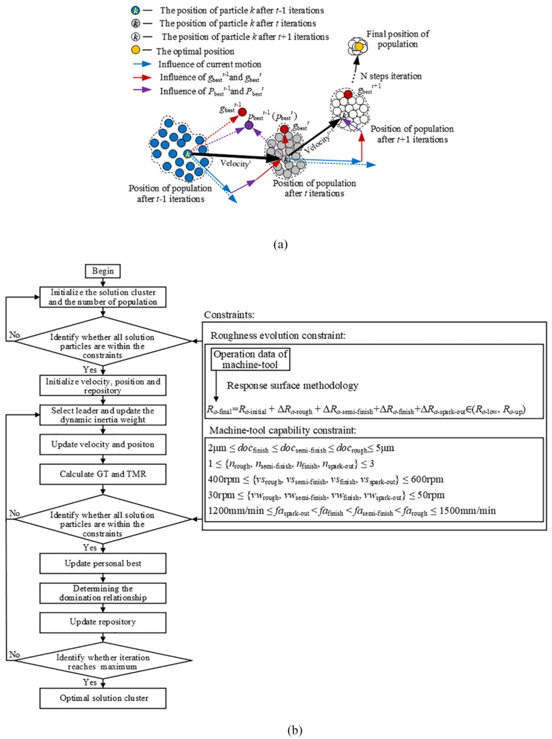
(a) The principle of the swarm optimization algorithm and (b) the flowchart of the multipass grinding process optimization strategy.
In order to verify the efficacy of the developed multipass grinding process optimization strategy, a practical application on grinding a steel roller with 1885 mm in length and Ф200 mm in diameter is implemented. The grinding efficiency is improved by 17.00% compared with the current empirical optimal process parameters that was planned by the experienced engineer. The result is exhibited in Figure 14.

Effectiveness verification of the multipass grinding process optimization strategy.
Conclusion and outlook
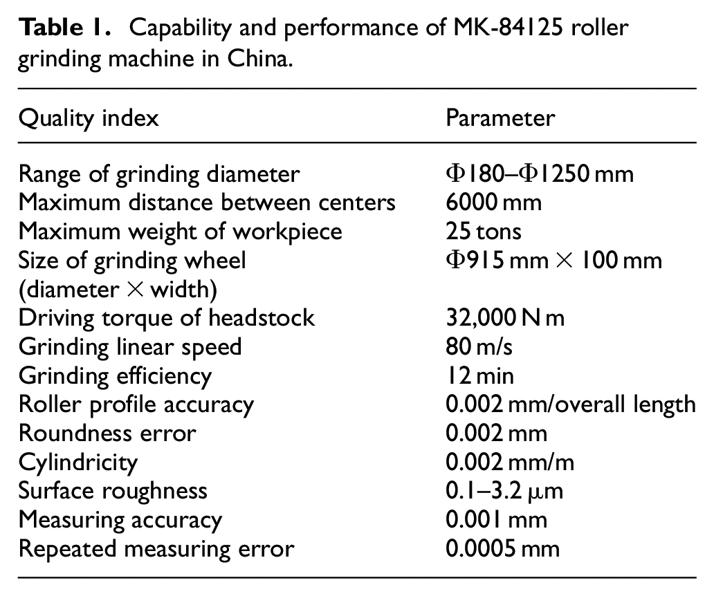
This article presents the state-of-the-art and emerging intelligent technologies in China’s roller grinding, including high-speed spindle and grinding machine platform, high-performance tooling design, in-process profile accuracy measurement and compensation, in-site machine vision for gloss defect, and intelligent process parameter optimization strategy. These critical enabling technologies provide support for steel industry upgrade toward higher stability, efficiency, accuracy, and intelligence, which is very meaningful for smart manufacturing. Table 1 summarizes the capability and performance for a commercialized roller grinding machine in China.
Capability and performance of MK-84125 roller grinding machine in China.
In the future, the main trend of roller grinding machine and production line includes:
Self-adaptive roller grinding machine with intelligent sensors, actuators, and control method.
Production decision based on cloud computing and machine learning.
Internet of Things (IoT) connectivity between different equipment and systems at the workshop level.
Roller workshop logistics for supporting continuous rolling production.
NC-manufacturing execution system (MES)-enterprise resource planning (ERP) connection, intelligent scheduling, and management.
Footnotes
Declaration of conflicting interests
The author(s) declared no potential conflicts of interest with respect to the research, authorship, and/or publication of this article.
Funding
The author(s) disclosed receipt of the following financial support for the research, authorship, and/or publication of this article: This research is supported by the Science and Technology Major Project of China-Advanced NC Machine Tools & Basic Manufacturing Equipment (2016ZX04003001).