
Abstract
Metal matrix composites are formed by adding certain filler particles to selected base metals to combine the good properties of both in the resulting composite and were proved to be quite promising in numerous applications. The main bottleneck lies in the processing methods, as the traditional solutions often lead to a loss of control on the dispersion of the filler material. The point-by-point consolidation mechanisms typical of additive manufacturing are proposed here as a possible means of enhancing this control over the composition of the metal matrix composites. Selective laser-melted composites with stainless steel 316L as the base metal and Si3 N4 as the filler phase are evaluated in the current study. The results clearly indicated that the dispersion of the filler particles is more controlled, as they are pushed and segregated around the solid front boundaries. The tensile strength of the composites is better than the pure 316L when laser-melted under appropriate process conditions. The surface quality is also substantially enhanced with the metal matrix composites.
Keywords
Introduction
Metal matrix composites (MMCs) refer to a class of materials in which two or more materials are combined by some means in order to achieve improvements in specific responses. Often, rigid ceramic reinforcements are embedded in ductile metal or alloy matrices, aiming to combine the good properties of both in the resulting MMCs, thus paving ways for better design options and solutions. 1 Metallic properties ductility and toughness are combined with ceramic characteristics, high strength and modulus, leading to greater strengths in shear and compression and higher service temperature capabilities. The unique features of MMCs in terms of high specific strength, elastic modulus and thermal stability attracted sufficient research attention and reporting.2,3 While aluminium, magnesium, copper and titanium are common base metals, fillers in different forms such as continuous or discontinuous fibres, whiskers and particulates are either mixed with or attached to the base metal particles and employed. Considering the availability of the relatively inexpensive reinforcements and the development of processing routes allowing for reproducible microstructures and mechanical properties led to the enhanced use of MMCs in aerospace, automotive and other structural applications.4–6 In particular, the great potential of manufacturing lightweight and structurally efficient aerospace components attracted significant attention.7,8
Traditionally, casting methods dominated the means of producing MMC parts, though segregation issues were at large. Later developments such as the molten stir casting techniques allowed us to overcome the problems to varying degrees.9–11 More recently, powder metallurgy-based methods are employed for processing such materials with better control on the dispersion of the filler component. With the production processes scaled up and the costs brought down, high-quality products could be achieved in large quantities and at reasonable costs. Components such as brake rotors and pistons, golf clubs, bicycle frames and extruded channels are common applications. Jet-turbine engine components operating at high temperatures have been developed based on super-alloy composites reinforced with tungsten alloy fibres. 12 Similarly, graphite/copper composites with tailored properties have excellent mechanical as well as electrical and thermal characteristics. 13 Titanium reinforced with silicon carbide fibres for aerospace applications and different steels and Inconel with titanium carbide particle inclusions for high temperature and corrosion resistance needs were other developments. 14 For the most part, the powder metallurgy method has been the dominant approach towards achieving control over the dispersion of the reinforcement filler materials and the metal–filler interface bonding conditions. 15 However, this method suffers from limitations such as the fabrication of complex shapes. Fully capitalising the benefits of developing metal-matrix components based on powder metals necessitates the invention of better processing methods.
Recently, layer-wise processing techniques have evolved rapidly from simple prototyping options to the more promising additive manufacturing methods.16–18 Selective laser sintering and melting are the most noteworthy powder bed fusion techniques of the additive manufacturing realm. The mechanism of consolidation by fully melting the powder substrates as employed in selective laser melting, in particular, is quite suitable for processing MMCs.19–21 Further, the ability to process powder mixtures opened up new and exciting material research opportunities. Several attempts have already been made considering selective laser melting of different composite materials22–25 and process simulations 26 and characterising and improving the mechanical properties of the promising candidate materials. 27 According to Kruth et al., laser melting allows for higher efficiencies in the material usage, better flexibility, near net shape production of complex forms and reduced processing costs in specific cases. 28 The ability to fabricate complex lattice structures by laser melting through process and melt flow controls was established, 29 while additive processing methods in general were considered as the promising means of near net shape manufacturing. 30 Evidently, selective laser melting appears to be a promising method to fully harness the benefits of MMCs based on powder metals, and some progress has already been made.
Exploring the laser cladding of metal-matrix coatings on pre-fabricated substrates, Byeong-Don et al. 31 identified the surface behaviour, coating thickness, and the effects of laser parameters on the coated layers. The most optimum process parameter combinations resulted in continuous layers, but in other cases, the layers suffered from either balling or discontinuities. Gu and Meiners 32 developed W–Ni–graphite elemental powder mixtures for processing and evaluation through selective laser melting, targeting bulk-form WC-based hard metals in situ. In similar studies undertaken using selective laser melting of powder mixtures such as extra low interstitial Ti6Al4V and 10 wt% Mo, 33 Ti and SiC, 34 AlSiMg with SiC and nanoparticles of MgAl2O4 at 10% and 1% by weight, respectively, 35 MMCs have also been shown to be beneficial to the additive manufacturing process; for example, Martin et al. used ZrH2 nanoparticles to stabilise crack formation in Al7075 and Al6061 using selective laser melting (SLM). 36
The ability to laser-melt mixed powder bed substrates leads to the possible use of the method for the direct processing of metal matrix systems. Use of cobalt-cladded carbide powder evaluated for laser melting of cutting tools was one of the early attempts in this direction. 37 Powders of B4C coated with metal by chemical vapour deposition (CVD) were processed using a selective laser melting system, and they established the suitability of selective laser melting for MMC powder systems. In spite of the specific benefits in terms of closely controlling the dispersion of the filler phase, in addition to the general benefits of layer-wise consolidation, the progress in the application of additive manufacturing for MMC materials is limited. It is essential to evaluate different MMC systems in particular with selective laser melting and establish the effectiveness of the material and process combinations. The current paper is an effort in this direction based on experimental evaluation of 316L stainless steel as the base metal. Specific attention will be paid to evaluate the ability of the point-by-point material consolidation mechanics unique to the additive processing realm to achieve the much needed control over the dispersion of the filler particles in MMCs. Consideration of the composite made of stainless steel and silicon nitrate fibres as the material for the case study is novel, as this is the first time these composites are used for selective laser melting.
Materials and methods
Stainless steel 316L, commonly used for selective laser melting, was the base matrix material in the current study and was sourced from Renishaw, UK. Si3N4 fibres developed by Nuenz in New Zealand were the ceramic filler material. Scanning electron microscopy (Hitachi SU-70) images of both the raw materials, 316L powder and Si3N4 fibres, are presented in Figure 1(a) and (b), respectively. It may be noted that the stainless-steel powder particles are mostly spherical in nature, with some irregularity in shape as well as size, with the average particle size at around 30 µm. The silicon nitride fibre contains both fibre and particles, with the fibre content being 80% by weight or volume. The fibres are of diameter 0.36 µm and length 14.5 µm, while the particles are spherical with a diameter of around 0.15 µm. A full characterisation has been previously reported by one of the authors. 38
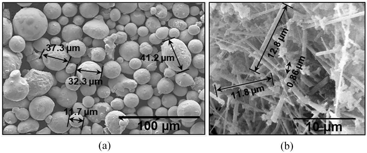
Scanning microscopy images (SEM) images of the (a) stainless steel (base metal) powder and (b) Si3N4 (filler) fibres.
The Si3N4 filler fibres are attached to the base metal particles by proprietary mechanical blending at Nuenz. Si3N4 was added to 316L at 1 vol%, which was determined to be the maximum surface loading for fibres based on studies previously carried out using aluminium powder. 39 Scanning electron microscopy (SEM) images of the 316L-Si3N4 blended powder particles are shown in Figure 2(a) at various magnifications. Overall, the particle size is observed to vary from 17 to 40 µm. Shape irregularities are consistent with the base powder. The coated Si3N4 phase appears plastered or smeared on the surfaces of the stainless-steel powder particles. This was evident from the dark areas in the SEM images owing to the lower electron density of Si3N4 compared to the 316SL alloy. . The presence of the filler particle is rather irregular, which is expected of the pulverising process. The length of the fibres is reduced compared to the original specification which is somewhat expected due to the mechanical blending process and the hardness of the 316L particles. Energy-dispersive x-ray spectroscopy (EDXS) analysis was carried out to identify the constituent elements, their relative proportions, and the general composition of the powder composite. The EDXS peaks, together with the composition in the weight per cent and elemental mapping, are presented in Figure 2(b). Si, Cr, Fe, Ni, and Mo are the key elements noted, and the composition confirms the powder composite prepared. Additional concentrations of Si and N were not identified in the EDXS, but at 1 vol%, it was insufficient to register on EDXS. The EDXS mapping (Figure 2(b)) showed that the dark particles homogeneously distributed on the 316L particles corresponding to Si as mentioned above. While the addition of the filler materials is anticipated to alter the mechanical properties of the laser-consolidated parts, 40 experiments are designed to establish the role of the Si3N4 filler fibres both on the laser consolidation mechanics of 316L and the ensuing mechanical properties.
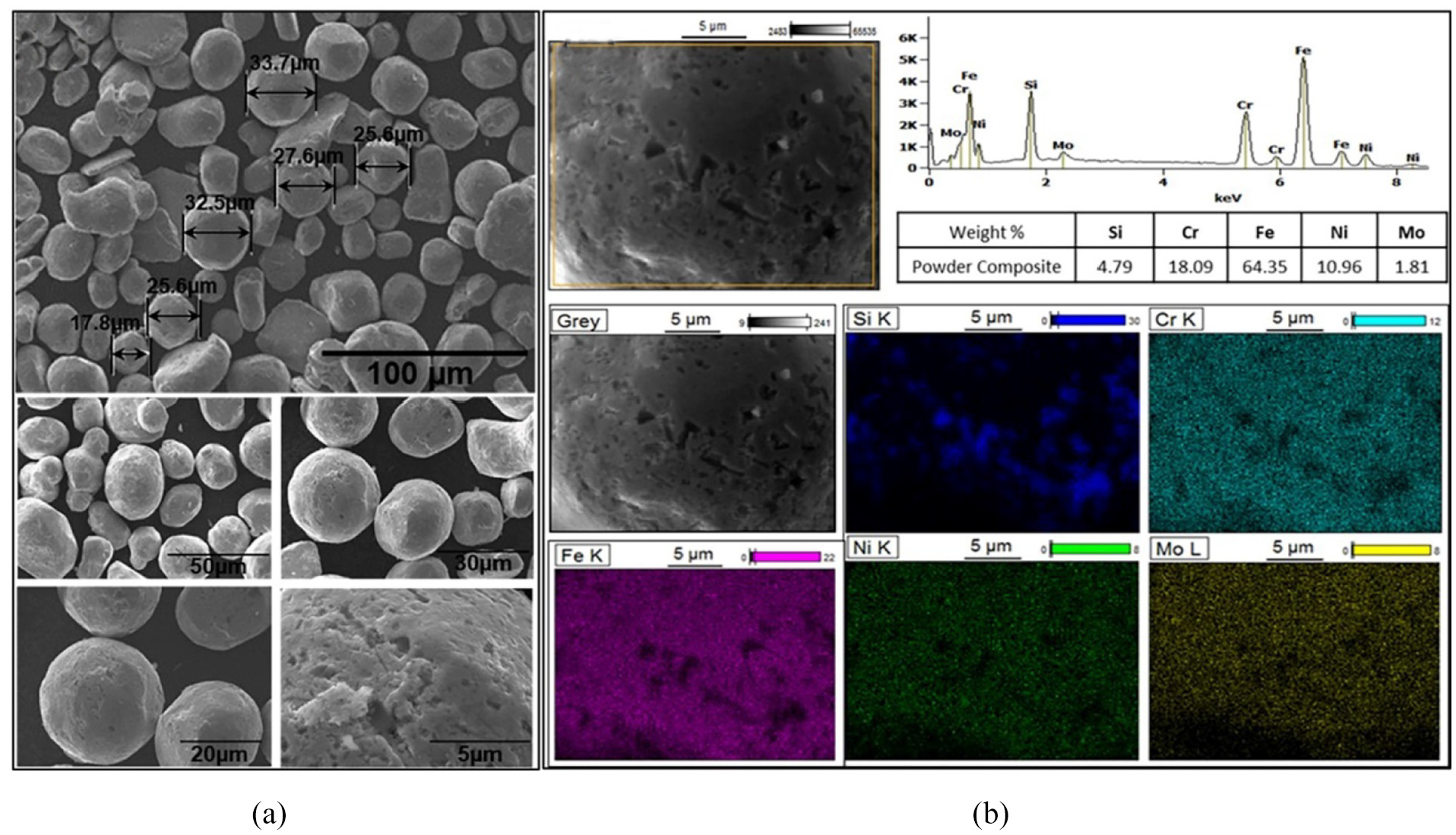
(a) SEM images of the stainless steel and Si3N4 composite powder and (b) EDXS (energy-dispersive x-ray spectroscopy) elemental mapping.
Preliminary work was done to establish the working ranges of the SLM process parameters, mainly laser power and speed. In order to avoid the compounding effects, the laser scan speed was initially kept constant at 750 mm/s, while the laser power was varied from 175 W to 225 W, in steps of 25 W. All these preliminary tests were conducted based on cubic samples of 10×10×10 mm size. Figure 3(a) presents the placement of the cubic samples on the build plate. The scan strategy involved zig-zag motion of the laser energy source from one end to the centre of the sample, covering the section area in two parallel patches. The scan lines and the sections used for the metallography studies are indicated in the inset. It may be pertinent to point out here that this kind of scan strategy leaves a poorly coalesced zone along the centre line of each section because of the heating of adjacent powders in differential times. However, this strategy is employed here in order to capture the possible role of the inclusions on the inter-strand coalescence at different time intervals.
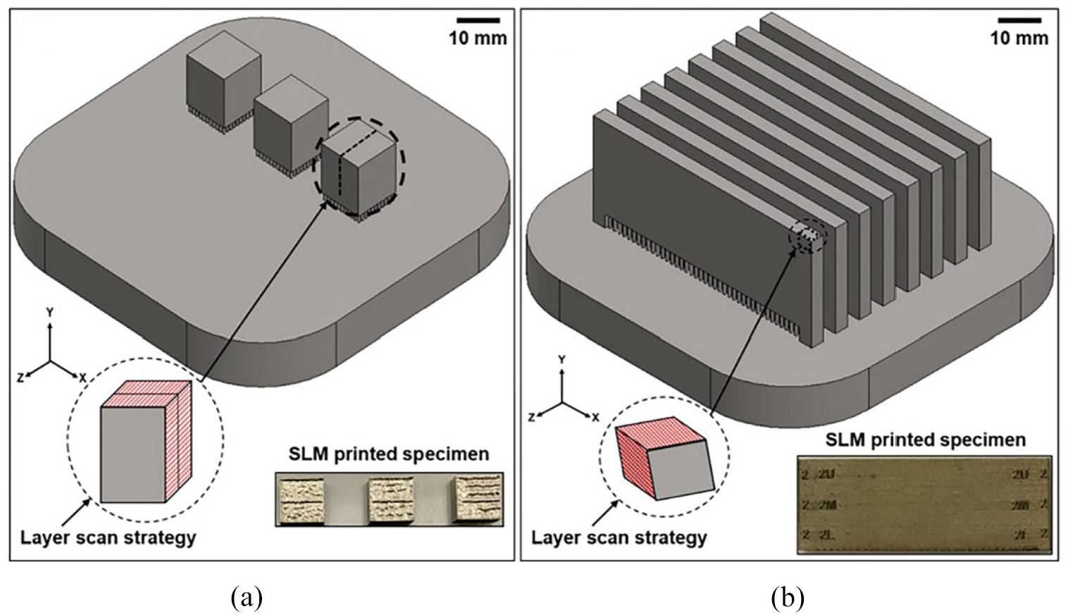
CAD file and selective laser melting (SLM) printing of the specimen used in (a) preliminary and (b) further experiments.
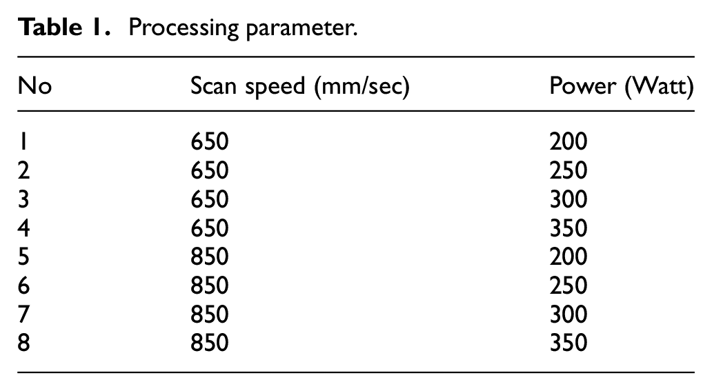
Based on the results of these initial trials, more elaborate experimental plans were developed for subsequent experiments, printing specimens for both metallographic and mechanical characterisation. Considering the time-consuming and expensive printing involved, a multi-specimen CAD model was designed to simultaneously print three tensile bars and six metallography samples for each process parameter combination. This printing strategy allowed for three repetitions of each tensile test and microstructural evaluation in a particular direction to be undertaken for statistical validation of the experimental results. Eight of these models were stacked parallel to one another as depicted in Figure 3(b), so that 8×3 = 24 sets of samples could be printed in each build, thus saving considerably on the pre- and post-printing tasks as well as the actual printing time. Printing for the whole experimental plan was completed in just two builds, one with 316L and the other with 316L plus Si3N4. Selective laser melting was done based on the Renishaw system at the Auckland University of Technology, New Zealand (Renishaw AM 400). The AM 400 system is equipped with a solid-state Nd:YAG laser (wavelength = 1070 nm) of 75 μm spot size. All samples were printed on stainless steel base plates using support structures with a height of 3 mm. The samples built were post-processed to develop the specimens for metallography and mechanical testing. Two speeds and four laser powers at each scan speed were selected, and the overall experimental plan is as shown in Table 1.
Processing parameter.
After printing and once the build plate was removed from the SLM system, the multi-specimen printed parts were removed from the build plate by breaking the support structures. Six metallography and three tensile test specimens were first cut out of each of the printed plates by wire electric discharge machining (EDM), as depicted in Figure 4(a). The tensile test piece dimensions were according to ASTM E370, and a representative specimen cut by wire EDM from the printed parts is shown in Figure 4(b) and (c). Tensile tests were conducted using the Tinius Olsen H50KS system available at the materials testing lab of the Auckland University of Technology at a loading rate of 3 mm/min all through.
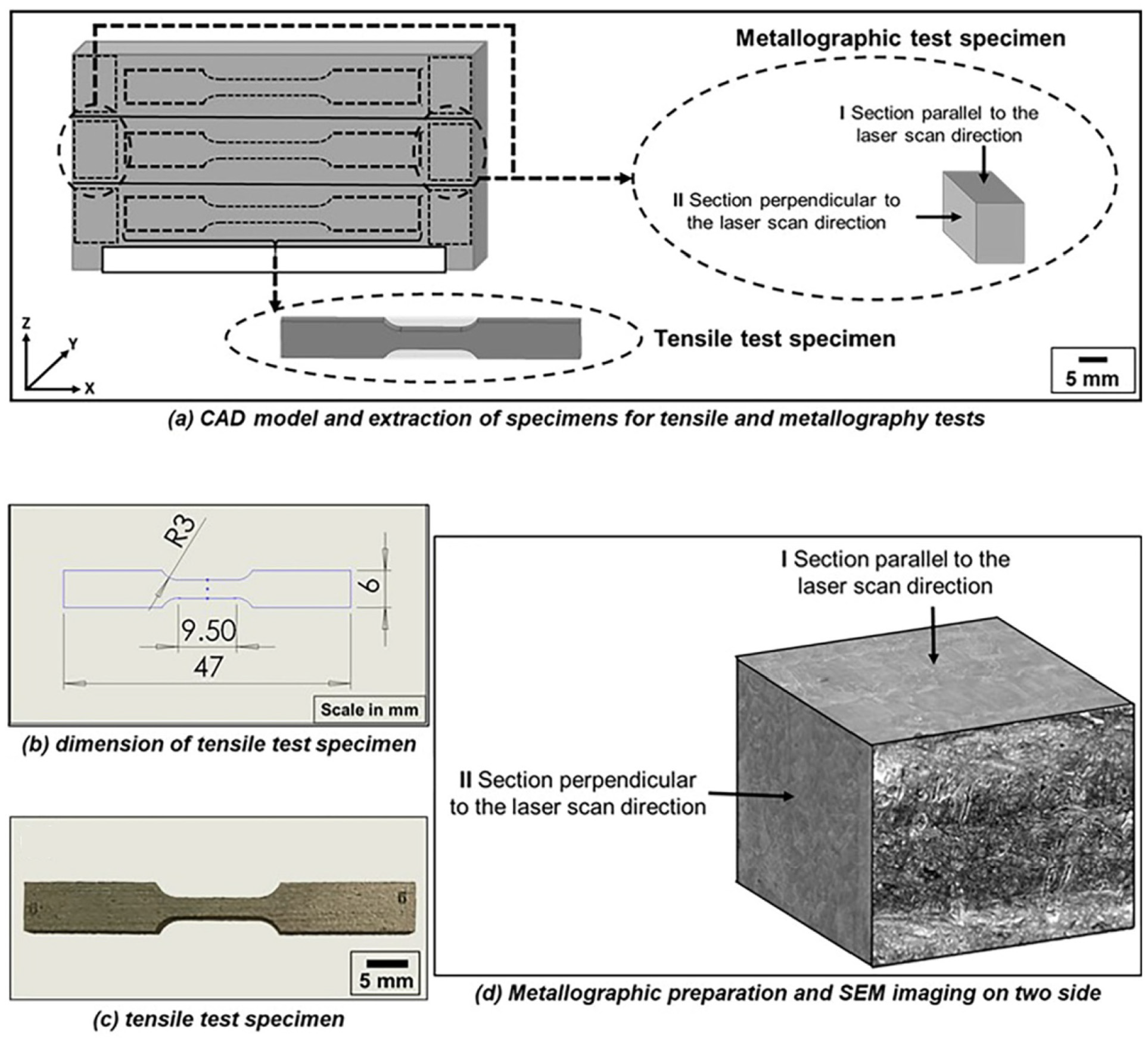
(a) CAD model to be printed (b), (c) test specimens and (d) metallographic preparation and SEM imaging on two different sections of each sample.
Two different microstructures were observed according to the SLM build direction. These corresponded to either side of the tensile test pieces. As depicted in Figure 4(d), these two sections, one parallel and the other perpendicular to the scan direction, were referred to as Section I and Section II, respectively. For microstructural examination, samples were mounted and polished as per the standard metallographic practices. Several etchants were tried, and finally, a mixed solution containing HNO3, HCl AcOH in the ratio 3:3:1, was found to react well and show the internal microstructures resulting from SLM processing. The optical microscopy was carried out using an OLYMPUS BX51M microscope fitted with a Nikon camera. Vickers hardness tests were conducted using a micro-indenter under a constant load of 300 g at 0.2 mm intervals across the samples to establish the variation of the micro-hardness levels in the laser-melted samples of different compositions. The samples collected for metallography were used for these tests. The tensile test specimens were also used to establish the surface roughness values based on Taylor Hobson Talysurf measurements. A sampling length of 10 mm and a stylus speed of 0.5 mm/s were employed. Considering the experimental costs and other constraints, optical and scanning electron microscopy images could be taken on only single specimens in each case. However, tensile and surface roughness tests are repeated on three samples each, and error bars are inserted into the graphs, which are indicative of the experimental reliability and repeatability.
Results and discussion
Preliminary tests
Microscopy images taken on laser-melted cubic neat 316L samples based on the preliminary test conditions are presented in Figure 5(a). While the scan speed is a consistent 750 mm/s for all these cases, each column corresponds to a particular laser power, as stated. Overall, material consolidation was sound and uniform. Micropores are noted in all the specimens, though the intensity increased with increasing laser power. Cellular dendritic growth of austenite was observed in all the samples, as evident from the images of higher magnification in Figure 5. However, depending on the direction of growth, the structure was seen as either columnar or cellular sections. The material consolidation mechanism was efficient in all these cases, as there was no evidence of any lack of fusion defects and inter- or intra-granular cracks. The laser scan lines were clearly seen at higher magnification, showing the boundaries between the successive fusion zones. Apparently, the pure 316L powder responded well as expected, within the ranges of the process parameters employed.
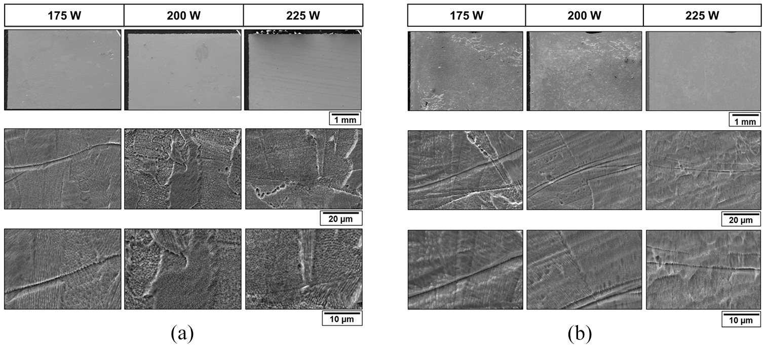
SEM images of laser-melted (a) SS 316L and (b) SS316L-Si3N4 metal matrix composite samples at a scan speed of 750 mm/s and varying laser powers.
Microscopy images taken on laser-melted specimens produced using the 316L-Si3N4 composites with the same process conditions are presented in the same manner in Figure 5(b). It may be readily visualised from these images that there was no evidence of any serious problems in the consolidation of the MMC through laser melting, which has to be taken as immediate success with the new metal nano-ceramic composite, though the quality of consolidation is yet to be established. Moving horizontally across the different rows of Figure 5(b), it can be noted that powder consolidation improved with increasing laser power, as the porosity levels decreased. Within the laser power ranges used in these preliminary trials, the sample produced at laser power 225 W and scan speed 750 mm/s settings resulted in the best consolidation and the least porosity. This is a contrasting result in the composite compared to the pure 316L, in which the porosity increased with increasing laser power, indicating that the nano-ceramic fillers had a clear role in controlling the liquid metal rheology during the laser consolidation process.
It is pertinent to point out here that the differential thermal attributes of the two constituents of the composite will influence the powder substrate responses to the laser energy input. First, the extent of the powder melting and the size of the heat-affected zone will vary according to the thermal absorptivity levels of the two material constituents and the effective specific heat of the powder composite. Further, the liquid pool rheology will vary with the viscosity, which in turn is a function of the temperature and time conditions.41,42 The time and temperature conditions for the melting and solidification at a given point will vary according to the laser spot size, which is 70 µm based on the Renishaw AM400 system used for the current experimental work and also obviously, the laser power and scan speed settings.43,44 For the same laser power and scan speed, the heat-affected zone appears to be reduced in the case of the MMC, compared to the pure 316L, which results in the reduction of the extent of melting and the viscosity of the liquid pool. This may be due to a slight reduction in the laser absorptivity in the presence of the nano filler materials and/or the increase in the effective specific heat of the powder composite. The end result is the increased porosity at the lower laser power settings evident in the micrographs of Figure 5(b). However, with the increase in the laser power, the optimum temperature and time conditions appear to have helped in improving the consolidation, as evident in the photomicrographs corresponding to the 225 W case in Figure 5(b). The size of the porous holes also decreased as the laser power increased. There is a general uniform dispersion of a single phase, austenite, while the solid front boundaries are visible clearly, probably because of the segregation of impurities or other compounds. The austenite formation followed cellular dendritic growth in the build direction, and the orientation of the cells changed in adjacent fusion zones, as the laser scan direction changed from one track to the other.
The low magnification optical microscopy results obtained from three sets of each of 316L and 316L-Si3N4 laser-melted samples are presented one below the other at different laser power settings in Figure 6. The images are on the cross sections of the cubic samples at right angles to the centre line of separation between the two raster patches on each section, as depicted in Figure 3(a). The layer-wise consolidation of the metal powders was evident from the microstructures. The lack-of-fusion problem is evidently central to the section in the cases corresponding to the last two columns of the first-row images. This is apparent from the scan strategy followed, which uses zig-zag raster paths that switch directions central to the specimen, as depicted in the inset in Figure 3(a). Also, a lack of interlayer fusion and a varying degree of delamination are evident at higher power ranges used with the 316L powder material. The presence of the Si3N4 nanoparticles appears to have overcome this problem to a large extent, as the microstructures in all the images of the bottom row of Figure 6 show a homogenised uniform dispersion of flat layers oriented parallel to the base plate and with strong inter-layer fusion and structural integration. Also, the favourable role of the presence of the nano-ceramic particles appears to increase with increasing laser power. It may also be noticed that the time lapse in heating the central portions at the meeting point of each laser scan patch on each section is also effectively handled by the thermal enhancements in the base material because of the presence of the ceramic nano-fillers. It is possibly due to a reduced thermal conductivity induced by the ceramic particles and the consequent preservation of heat locally during the course of melting and solidification point by point.
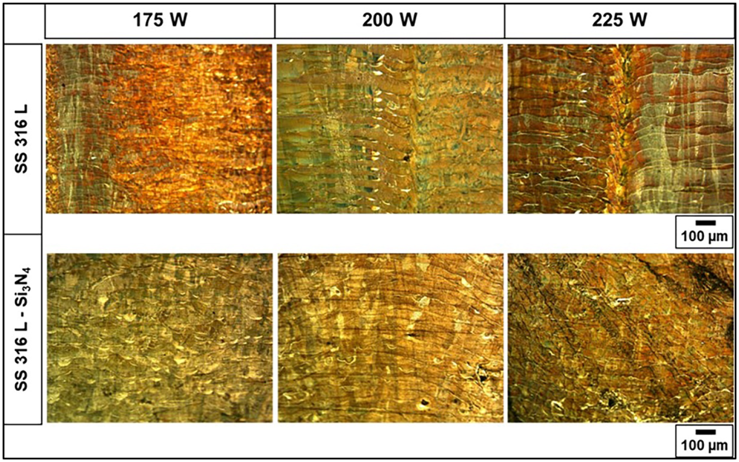
Optical microscopy of laser-melted samples using the preliminary settings, 750 mm/s scan speed and varying laser powers.
Further experimental studies
Optical microscopy
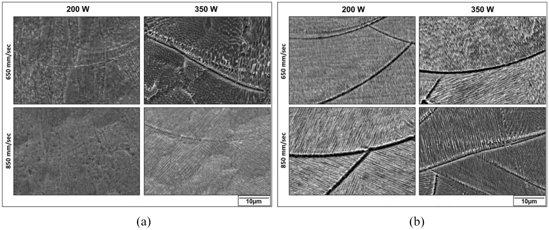
Optical microscopy results based on laser-melted 316L samples at a broader range of laser powers and two different scan speeds (650 and 850 mm/s) are presented in Figure 7(a) (i) and (ii), respectively. At the lower speed and lowest power (200 W), there was considerable porosity. Better consolidation was evident, as the power increased beyond 250 W. The lower scan speed leads to an improved consolidation time, and as a result, the solidified liquid pools appear to be considerably elongated in the build direction at 200 – 300 W. However, at 350 W, the layers flattened, and there was a complete lack of the elongation of the solid troughs. This was mostly due to excessive heating, re-melting and the ironing of the layers, as they are stacked one over the other. At a higher speed (850 mm/s), the liquid pools and the solidified troughs appear to be confined to individual layers at all the laser power settings, as shown in Figure 7(a) (ii). There is evidence of a finer dendritic growth of the solid across the boundaries of the liquid fronts from adjacent layers. This is due to the high speed and less time allowed for the heat to flow and the subsequent heat transfer across the layers.
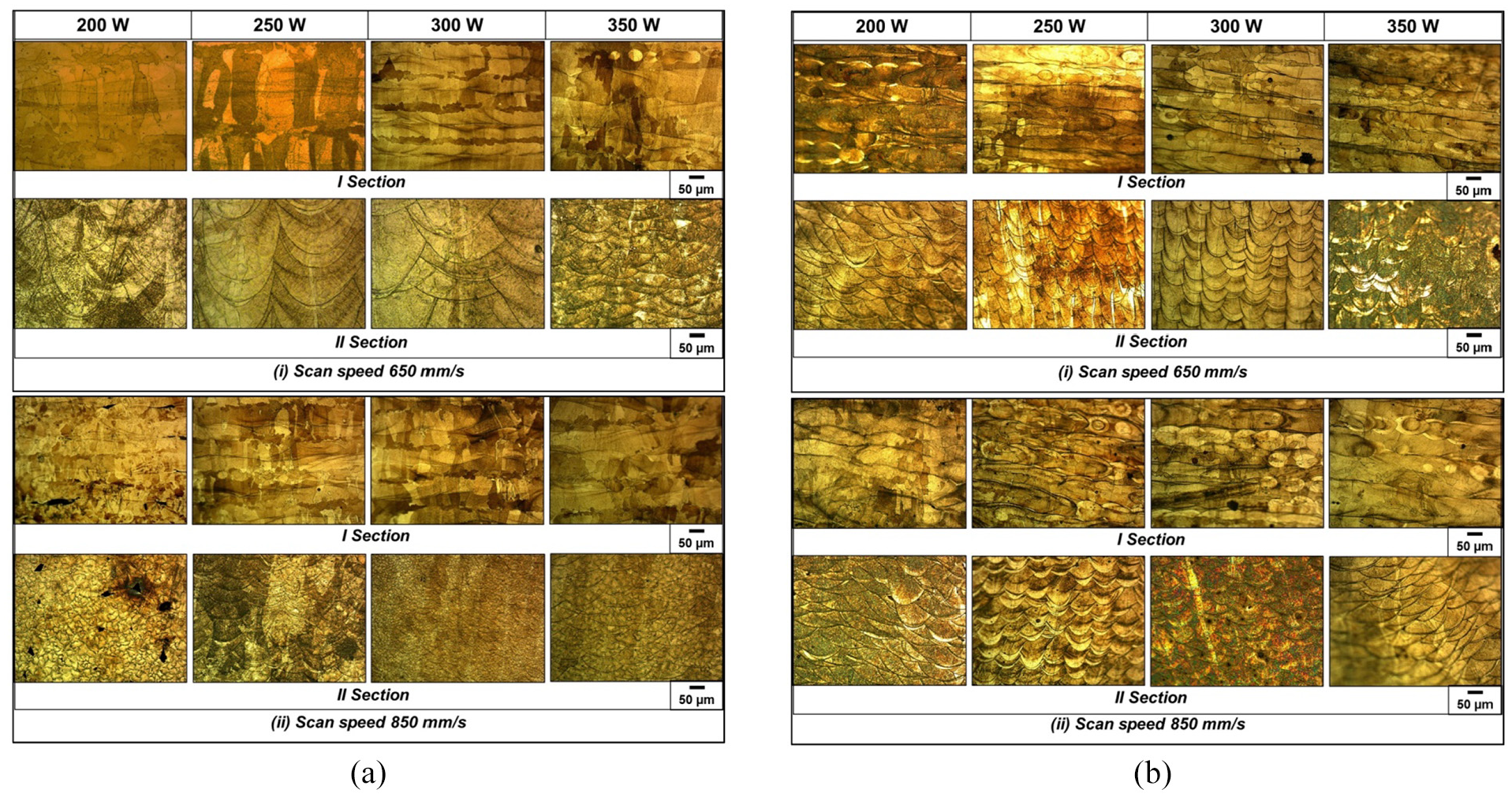
Optical microscopy based on laser-melted (a) SS316L and (b) SS 316L-Si3N4 samples.
Optical microscopy results of samples based on 316L plus Si3N4 MMC with similar process conditions are presented in Figure 7(b) (i) and (ii). Striking differences may be noted consistently across the whole range of experimental conditions by comparing the images in Figure 7(a) and (b). The presence of the Si3N4 particles led to a very clear and contrasting definition of the solid trough configurations emanating from the laser melting and solidification mechanisms. There is no evidence of any inter-strand or inter-layer dendritic growth. It is probably due to the segregation of the filler particles around the boundaries of the liquid pool columns generated, as the laser scan paths lead to the melting of the powder composite. It may be a favourable result, in that the dispersion of the fibres appears to be confined to the boundaries of the liquid pools generated. Close control over the layer size and the raster path patterns would then allow for control of the dispersion of these particles across the metal matrix. There was a certain similarity in the elongation of the solid troughs at a lower scan speed, as was the case with the pure 316L under similar conditions. Also, at a higher scan speed, the layers were flat and ironed.
Evidently, the heat-affected zones are much wider in the case of the pure 316L, compared to the 316L plus Si3N4 MMC. As already expressed, this is most probably be due to a loss of thermal conductivity in the composite due to the presence of the nano filler fibres. As a result, heat is preserved in each liquid column, confining it to its own space during the solidification process, with relatively less inter-strand coagulation. The sharply defined solid front lines are indicative of this localisation of the solidification process and the segregation of the filler particles and other impurities along the solid fronts. It is advantageous as the prolonged heat preservation within the solid columns or beads will lead to better temperature and time conditions and a denser solidification locally. However, the lack of coalescence across the inter-strand boundaries could lead to a lack of consolidation and also fusion defects, which is possibly the reason for the relatively higher level of porosity, particularly at lower energy densities, as evident from the 175 W and 200 W cases of Figure 5(b).
Scanning electron microscopy
SEM images of the laser-melted 316L and 316L plus Si3N4 samples are presented in Figure 8 for varying combinations of process parameters as depicted. An immediate observation that can be made from these images is that the solid front lines are sharp and clearly defined in all the cases of the composite, compared to the pure 316L cases. This further reinstates the hypothesis that the lighter nano-filler particles drifted away to the boundaries of the liquid columns because of Brownian motion and possibly surface tension forces and acted as barriers to the inter-strand growth of the dendrites. Being a line-by-line consolidation technique, the inter-strand metallurgical bonding plays a significant role in the densification of the solid phases in selective laser melting. Also, the critical cooling rates are considerably high, resulting in microstructures completely different from other manufacturing processes.43,45 While the compositional fluctuations and the constitutional super cooling lead to the cellular structures, the relatively higher undercooling favours dendritic mode of solidification. 45
SEM images of the laser-melted (a) SS 316L and (b) SS 316L-Si3N4 specimens.
Increased thermal capacity of the composite powder could also be the cause for these clearly defined solid fronts. A reduction in the heat capacity could lead to a relatively less temperature rise for the same energy input and perhaps a faster cooling at the boundary of each liquid column. However, because the thermal conductivity of the ceramic is lower, there is also the possibility for the heat energy to be trapped inside the liquid column, allowing the nano-fillers to have a better chance to clearly migrate to the surface and thereby leading to a clearly defined solid front structures. In particular, with the low laser power and higher scan speed cases, the solid boundary lines are even more clearly dark and wide, indicating a possible dent all along, as evident from the first images of the bottom row of Figure 8(b), corresponding to a scan speed of 850 mm/s and a laser power of 200 W.
Further, high-resolution SEM images were obtained based on the FEI NanoSEM 450 system available at the Robinson institute of the Victoria University of Wellington. The results are presented in Figure 9. As evident from the image shown in Figure 9(a), dark particles are segregated both at the melt pool boundary as well as along certain wavy patterns. A closer look at the image shown in Figure9(b) indicates a wavy distribution pattern for these particles inside the melt pool area. This is likely due to the original packing of the spherical particles of the matrix metal in the powder bed. Figure 9(c) shows that these are clearly crystalline particles at the solid boundary. The dark colouration under back-scatter conditions is indicative of lighter elements in this phase with a lower electron density compared to the major phases present – consistent with Si3N4. Further, Figure 9(d) shows the particles segregated at the grain boundary as discrete crystalline inclusions at around 500 nm in size. The EDXS analysis of one of the big particles, as shown in Figure 9,(e) is probably indicative of chemical interactions between the fibres and the 316L, leading to the formation of FeSi, N and SiC.
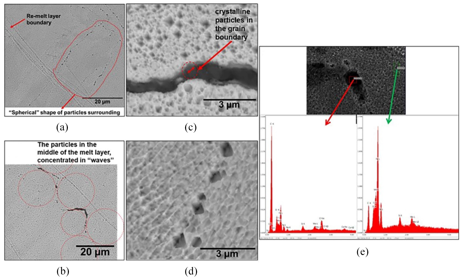
SEM images of the laser-melted SS 316L plus Si3N4 metal matrix specimens: (a), (b), (c), and (d) SEM images, and (e) energy-dispersive X-ray spectroscopy results of the laser-melted SS 316L plus Si3N4 metal matrix specimens.
Mechanical testing
It may be observed that the micro-hardness values are almost steady in the 316L case based on the results presented in Figure 10. However, the MMCs resulted in an almost sinusoidal variation for the micro-hardness values across the specimen, as shown in Figure 10. This could be due to the segregation of the fibre particles at the boundaries and the consequent periodic variation in properties across the specimen section. There are specific points, where the micro-hardness values of the composite are lower than those of the pure 316L case.
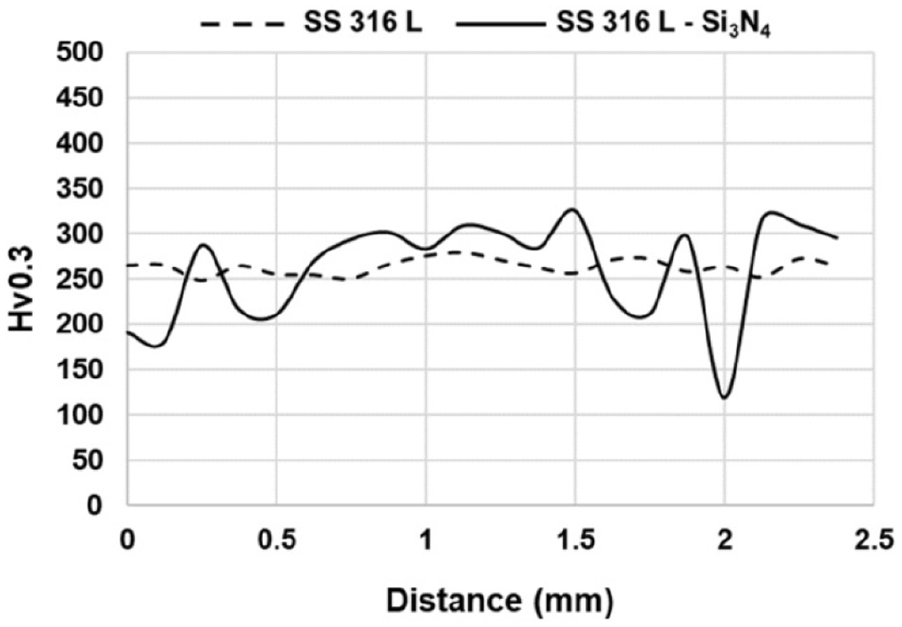
Comparison of micro-hardness values of laser-melted SS 316L and SS 316L-Si3N4 samples.
The images of the printed samples of 316L and 316L plus Si3N4 composites after stretching and breaking under tensile testing are shown in Figure 11(a) and (b), respectively. The stress–strain graphs of the specific cases laser-melted at 250 W and a scan speed of 650 mm/s are presented in Figure 11(c). In this particular case, the ultimate strength slightly decreased in the case of the composite, while the ductility slightly improved. For a better comparison of the relative qualities of the two material compositions, the ultimate stress values obtained with varying laser power and scan speeds of 650 mm/s and 850 mm/s are presented in the graphs of Figure 11(d) (i) and (ii), respectively. At the lower scan speed, 650 mm/s, the ultimate tensile strengths of the composite samples are higher than those of the pure 316L samples at all the power settings used, as evident from Figure 11(d). The higher speed, 850 mm/s, however, shows a compounding effect with the laser power and the composition. The composites gave slightly higher strengths compared to the pure 316L up to 250 W laser power. From 250 to 350 W, the pure 316L samples scored a lot better in terms of the ultimate strength compared to the MMCs, as may be observed from Figure 11(d).
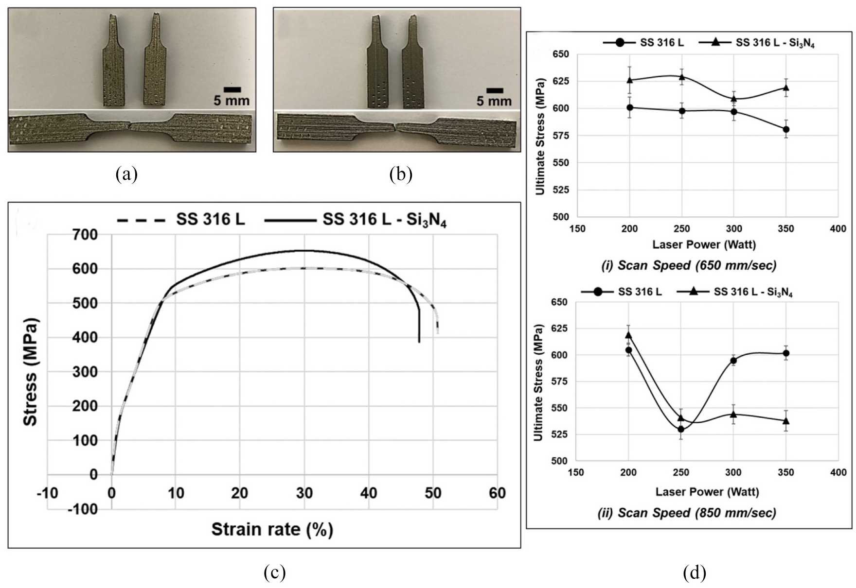
Tensile tests and results based on samples laser-melted at power 250 W and a scan speed of 650 mm/s: (a) stretched SS 316L, (b) stretched SS 316L-Si3N4, (c) stress–strain graphs of both SS 316L and SS 316L-Si3N4 and (d) ultimate stress result for SS 316L and SS 316L-Si3N4 at 650 mm/s and 850 mm/s scan speeds.
The variations in the tensile results can be related to the structural transformations induced by the nano-filler particles. As was already noted, the heat flow conditions within the substrate are restricted, possibly because of a reduction in the thermal conductivity with the addition of the silicon nitrate nanofibres. The consequent local conservation of energy leads to slightly overheated cores and a relatively prolonged liquid state for the outer reaches of each raster strand. This will allow the filler particles to segregate at the peripheral regions of the columnar beads forming along the raster lines. The insufficiently coalesced inter-strand boundaries, being the sources of miss-match and possible obstacles for the dislocation movements, could have caused the improvement in the tensile strength of the laser-melted composites at all laser power settings and 650 mm/s scan speed, as depicted in Figure 11(d) (i). At the higher scan speed of 850 mm/s, the tensile strengths of both material cases reduced, compared to the corresponding 650 mm cases, because of the excessive speeds, turbulence in the liquid pool and the consequent cavity formation. The effect is more pronounced at higher power settings 300 and 350 W, as is evident from the increased presence of cavities in the images of Figure 7(b) section II, corresponding to the two higher laser power cases. Evidently, there are interactions between the laser power and scan speed settings, and a more comprehensive design of the experiment is needed to completely understand the system and establish the optimum parameter levels. Within the limits of the process parameters used, the 650 mm/s scan speed allows us to achieve an overall 4.1% higher ultimate tensile strength in the case of the composites at all the power levels.
Surface roughness measurements, as seen in Figure 12, show a clear improvement in the case of the MMCs at almost all the parameter combinations used. In particular, with the lower scan speed case, as depicted in Figure 12(i), the 316L-Si3N4 composite specimens showed an almost 5–6 µm lower surface roughness compared to the pure 316L samples. In selective laser melting, the surface roughness of the bounding surfaces is mainly affected because of either excessive heating and absorption of the partly melted particles from the immediate vicinity of the part envelope or the relatively lower heating and a lack of consolidation of the particles at the outer periphery. In the current case, the presence of the filler particles has apparently lowered the thermal conductivity of the substrate and led to an overall preservation of the heat within the part envelope and allowed a better confinement and formation of the outer surfaces of the built specimens. Overall, the presence of the fibre particles had a clear role in the variation of the mechanical and physical properties of the laser-melted samples, while the optimum settings will have to be established based on the target responses.
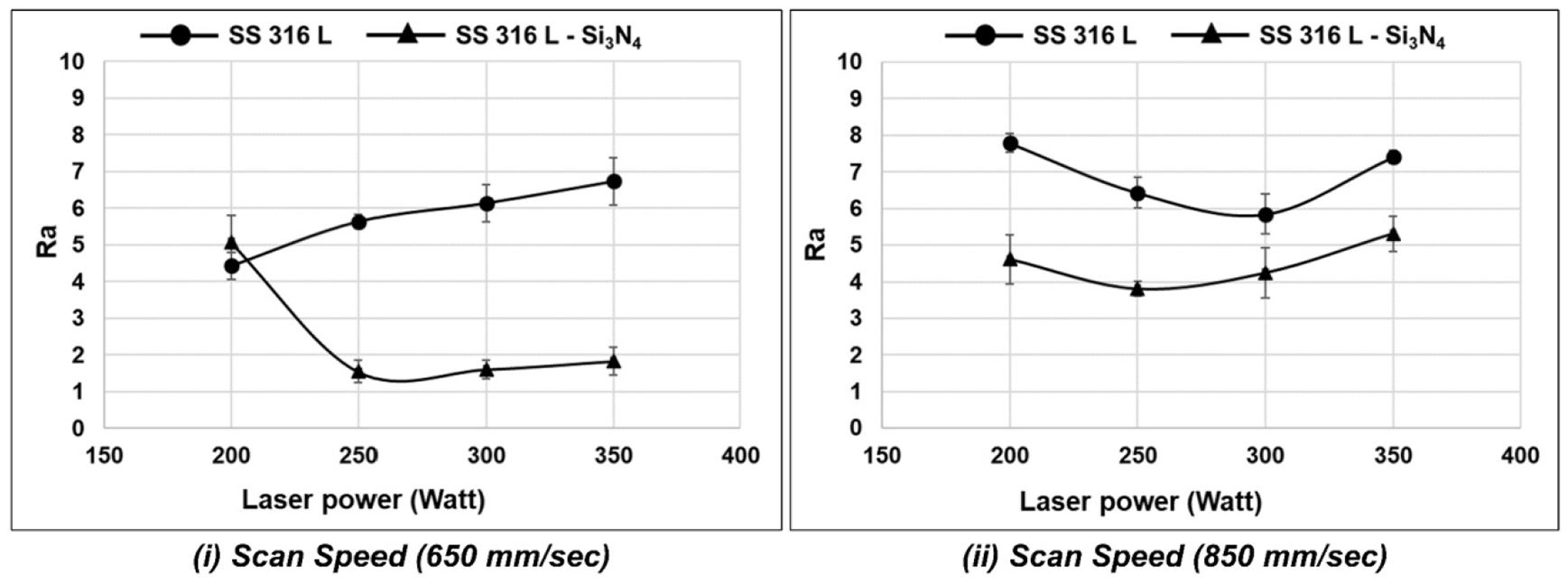
Comparison of roughness values of laser-melted SS 316L and SS 316L-Si3N4 specimens.
Conclusion
Both stainless steel 316L and its composite with Si3N4 in the powder form have been analysed experimentally by printing test pieces based on the selective laser melting process. Metallographic, mechanical, and physical tests were conducted on the laser-melted specimens and evaluated comparatively. The presence of the fibre particles had a marked influence on the rheology of the matrix metal during the liquid-state sintering stage. The filler particles mostly occupy either the grain boundaries or the boundaries of the solid fronts formed by repeated laser scanning. Critical interactions between process and material parameters are evident from the current results and a comprehensive design of experiment considering all experimental factors should be undertaken in the future to optimise the responses of the new MMC for processing by selective laser melting. Other observations include the following:
The elongation of the solid fronts and the fine dendritic growth across the boundaries are arrested by the segregation of the filler particles in the case of the MMCs.
The tensile strength of the laser-melted MMCs is higher than that of pure 316L at a lower scan speed of 650 mm/s.
At 850 mm/s, the laser-melted MMCs show a slightly higher strength over 316L up to 250 W power, but beyond that, the result is reversed, as 316L shows much higher tensile strength compared to the MMC.
The micro-hardness results are consistent with the pure 316L, but the MMCs show a cyclic variation.
After selective laser melting, the surface roughness values of the 316L plus Si3N4 composites are almost 73% better than those of pure 316L.
Footnotes
Declaration of conflicting interests
The author(s) declared no potential conflicts of interest with respect to the research, authorship, and/or publication of this article.
Funding
The author(s) disclosed receipt of the following financial support for the research, authorship, and/or publication of this article: The authors wish to acknowledge the support received through the MBIE funding subcontract from the New Zealand Product Accelerator of the University of Auckland.