
Abstract
Down-the-hole drilling is a reliable method for drilling in medium-to-hard geological structures. The insert-hole fitting interference value emerges as one of the most important factors of down-the-hole drilling bit life. In this study, fatigue tests were conducted using a tungsten carbide pin press-fitted into a hole in the specimens of DIN 1.6580 steel (which is used for manufacturing the bit body) to quantify the effect of interference value on the bit body failure. Then, the process of bit-rock collision was simulated using three-dimensional finite element method taking into account the residual stresses in the insert and bit body to determine the optimal interference value. Simulations were performed considering the rotary motion of the bit in addition to impact for a single-insert as well as a commercial 3.5 inch bit. Results showed that the interference value influences fatigue life significantly. Also, the velocity and angle of impact have considerable influence on body stresses. Results of this study can greatly assist the design of insert-hole manufacturing tolerances in down-the-hole bits.
Introduction
Down-the-hole (DTH) drilling is a rotary-impact drilling method widely used in mining, exploration, water well drilling, road construction and other drilling operations around the world. 1 In this process, bit failure is mainly because of tooth loss, fracture and wear. Lost teeth are usually peripheral ones on the inclined plane of the bit end face. Tooth loss has also been observed due to bit body fracture around holes as a result of fatigue failure. 2 Interference fit is widely used in the fixed connection of mechanical parts for its simple structure and high torque (and force) transmitting capabilities. 3 Cylindrical button inserts are pressed into the bit body. This method holds the button in the body without defects such as undesirable residual stresses and other defects resulting from soldering (another method for joining an insert to the bit). Joining by plastic deformation has a lot of advantages, capable of joining a broad range of similar and dissimilar materials in an environmentally friendly manner. Weight and cost reduction occur due to elimination of joining elements such as bolts, screws, rivets and welding electrodes. On the other hand, applying high temperatures is not required. Thus, a considerable energy saving can be achieved, and subsequently, thermal and residual stresses as well as metallurgical evolutions can be avoided. It has been proved that interference fit protects the hole from crack propagation. Several studies have shown that using interference fit fasteners increases the fatigue life of structures. 4
Zhang et al. 5 researched the design of interference fits using finite element method. Gear-wheel interference fit studies exposed the traditional design method as having limitations. Using finite element method (FEM) to analyze the stresses of three-dimensional interference fits offers more accurate results than traditional methods. They utilized two safety factors to provide a new approach to assess the quality of interference fit. Selective assembly method along with the FEM-based approach to design interference fits yielded more reliable joints and more precise assemblies at lower production costs. 5 Arslan 6 executed a complete cycle of shrink-fit tool holder design analysis considering transient thermal and structural coupled FEM. The fitting procedure sequence was the expansion of the tool holder inner hole using inductive heating, so that cutting tool is easily inserted. Following this, both the tool holder and cutting tool were allowed to cool down to form a shrink-fit joint. Required nominal interference fit value and resulting stress levels were determined accordingly. 6 Huang et al. 7 presented a novel human–robot collaboration (HRC) method based on active compliance for a common disassembly task (separating press-fitted components). The concepts of human–robot collaboration are introduced, and the method of active compliance control is outlined first. Then, a case study designed to demonstrate the proposed method is detailed. As a validation, the study involved the disassembly of an automotive water pump utilizing an industrial robot. The article proposes valuable ideas which can be useful in disassembling (and assembling) press-fit joints. 7 Liu et al. 8 studied residual stress field and fatigue performance of cold expanded holes. Considered parameters include friction between the mandrel and hole surface, plate dimensions and simulation techniques. Results showed that the tensile and compressive residual stresses increase as interference value increases. Residual stresses vary greatly depending on the plate thickness and the location at the plate thickness. Cold expansion can decrease surface roughness of the hole and extend fatigue life up to about six times. Also, the crack always initiates near the entrance face in cold expanded specimens. The best interference value was reported between 4% and 6%. 8 Zeng et al. 9 conducted a comprehensive study on the residual stress distribution in a plate that resulted from initial interference fit and squeeze force in a riveting process. Following a finite element simulation, an analytical model of the riveting process was introduced and then a fracture analysis of fatigue loading was performed. Non-uniform expansion along the axis of the hole was observed, which resulted in a non-uniform distribution of through-thickness stresses. High compressive stresses were observed around the hole in tangential direction because of interference fit that shows fatigue life increase effect. 9 Jiang et al. 10 studied the influence of interference fit value on hole deformation and residual stresses in a hi-lock bolt (Ti alloy) inserted into an aluminum alloy lap specimen. A two-dimensional (2D) FE model of the process was also developed revealing consistency in the analytical forecasts and experimental data. A quantitative analysis of the insertion force history, non-uniform hole expansion, protuberance and residual stresses of the interference fit was presented. 10 A new theoretical model to predict the stress distribution in interference fits was proposed by Wang et al. 11 In this simplified model, it was assumed that the problem was plane strain and a non-uniform linear load acted on a semi-infinite plane. Stress distributions of different material pairs under full contact conditions were also analyzed. The theoretical results showed good agreement with the numerical ones. 11 Zhang et al. 12 proposed an analytical model of interference fit for electromagnetic riveting process considering different affecting parameters. Residual stress distribution as well as elastic–plastic deformation of the rivet and sheets were predicted. Theoretical model was verified by experimental electromagnetic riveting process of 6082 T6 aluminum alloy sheets and 2A10 aluminum alloy rivets. 12 Kim et al. 13 analyzed a micro-scale pin-hole interference fit assembly under repeated insertions of tungsten carbide pin into an aluminum hole. Force measurement results revealed that most of the plastic deformation occurred during the first insertion, since the next insertions showed the same magnitude of force. The shear stress results obtained using thick-walled cylinder model matched the experimental values well. 13 Pedersen 14 performed design modifications on hub geometry (different side-surface designs) considering the pressure distribution in contact surface of an interference fit as the main factor effecting fatigue failure. It was shown that the stress concentration at the end of the contact interface can be reduced or removed by specific geometry designs of the hub. The suggested designs can be applied where they are feasible and physically obtainable. 14
Bu et al. 1 studied impact stresses of rock, piston, bit and buttons (inserts) in DTH drilling process via three-dimensional (3D) simulations. The main effective factors such as piston velocity and rock material were investigated. In this analysis, all materials were considered as isotropic elastic, except for rock. However, residual stresses resulted from interference between the buttons and bit body were not considered. 1 Saksala et al. 15 developed and validated a method including a recently introduced constitutive model to describe rock fracture and bit-rock interaction. The constitutive model had a viscoplasticity part to indicate the stress states leading to rock fracture along with a damage model. The damage model included separate damage variables for tension and compression. In the numerical examples, the approach was validated by simulations of the dynamic Brazilian disk test and dynamic indentation on Kuru granite. Simulations of multiple consecutive impacts with a 7-botton commercial bit showed that the approach was able to predict the experimental rate of penetration (ROP). 15 Zhang et al. 16 performed computational fluid dynamics (CFD) analysis along with dynamic mesh method to evaluate the performance of reverse circulation down-the-hole (RC-DTH) air hammers. The influences of rebound coefficient, input air pressure and piston mass on the performance of the air hammer were studied. It was revealed that increasing the rebound coefficient and input air pressure can improve the impact performance of the air hammers. However, increasing input air pressure can increase energy consumption and reduce efficiency. On the other hand, increasing the piston mass would drop the performance of the air hammer. 16
From the previous studies, it can be perceived that there is a lack of data on the effect of interference value and resulting residual stresses on the bit body as well as fatigue performance of DTH bits. The objective of the work presented here is to find an interference range for fitting the inserts in the bit holes to obtain a more uniform stress distribution and maximize fatigue life. To this end, fatigue tests were carried out on interference fit assemblies of tungsten carbide pin and DIN1.6580 steel hole. Comprehensive dynamic impact simulations of rock drilling process were next conducted to obtain stress distribution in the bit. In contrast to previous works, this study focuses on bit body stresses, taking into account the effect of stresses resulting from the insert-body interaction. In addition, the effects of rotation and impact as well as the speed and angle of collision were investigated. Based on the research results, a 3.5-inch DTH bit was manufactured and tested in site drilling operations which showed promising performance in practice.
Interference fit equations
In order to secure the button during drilling, interference fitting of the buttons in the bit body is used. When a cylindrical component is assembled in another by shrinkage or press fit, a contact pressure is created between the two components. Stress for an interference fit can be obtained considering the shaft to have uniform external pressure and the hub as a hollow cylinder facing uniform internal pressure. Since there are tolerances for both diameters, the maximum and minimum pressure can be achieved applying the maximum and minimum interference. Based on Lamé theory, the interference required to develop a given contact pressure (p) is calculated using the following equations:
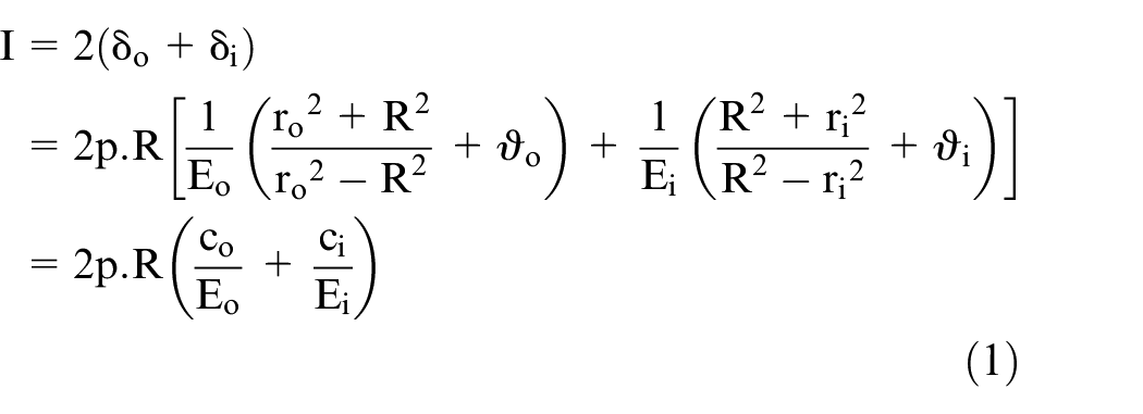
where
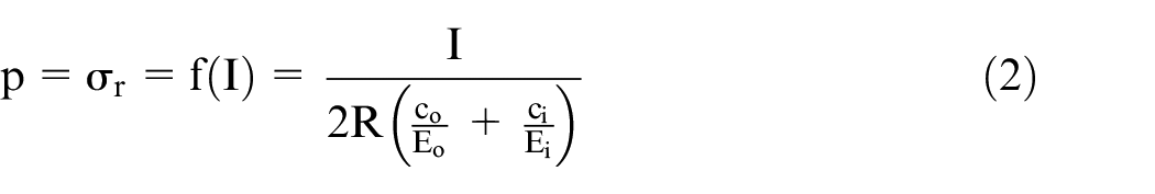
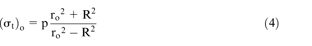
Since R, E and c are constants, the contact pressure forms a linear relationship with interference. Tangential stress
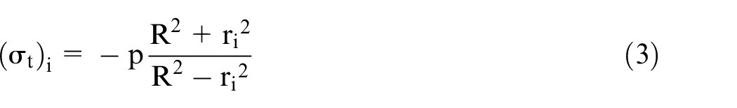
Outer member tangential stress is tensile:
It is worth noting that the traditional design method for interference fits is usually guided by tables obtained using the Lamé equation that applies 2D stress analysis for elastic loading.
Experiments
Material
Material considered for manufacturing the bit was a low-alloy, high-strength steel DIN 1.6580. To obtain mechanical properties of the bit body, spectrometric analysis of the material chemical composition was performed and the following experiments were carried out.
Tensile tests
Tensile test specimens were prepared with 20-mm gauge length according to ASTM E8 protocol. Specimens were then hardened and tempered to hardness of 490 Vickers. To obtain the material stress–strain curve, tensile tests were performed on the specimens using Instron8502 Test Machine. Fractured samples experienced a partly ductile failure with modest necking.
Fatigue tests
A DTH drilling bit undergoes a large number of impacts during its life, making it necessary to study fatigue performance of the bit. To this end, Fatigue tests were carried out on interference fit assembly of specimens manufactured of bit-body material with tungsten carbide pins (the same as inserts). Fatigue test specimens were prepared as shown in Figure 1(a) with a hole at one side for pin insertion. These specimens were also hardened and tempered to hardness of 490 Vickers. Based on the initial evaluations (i.e. literature review and screening tests), hole diameter values (D) were determined and machined to obtain interference values of 0.3, 0.6, 0.9 and 1.2 percent. The pins with diameters of 12 ± 0.001 mm were considered for these tests. Holes for the given interferences were machined and eccentrically ground precisely to ± 0.004 mm tolerance.
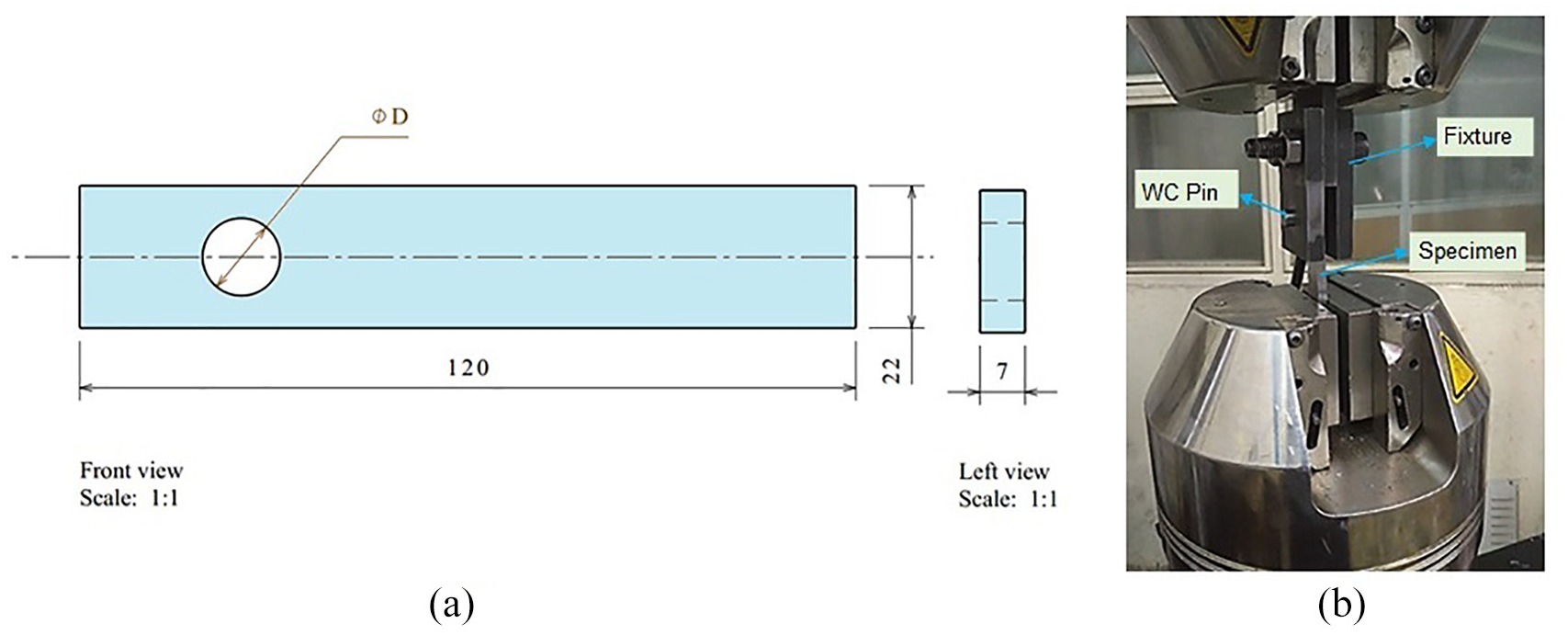
(a) Dimensions of fatigue test specimen (mm). (b) Fatigue tests using a designed fixture.
Again using Instron8502 machine, tungsten carbide pins were inserted into the holes of the prepared specimens and fatigue testing was performed. Three specimens (tests) were considered for each interference value. Since the alignment between the pin and hole was crucial for creating precise and consistent joints, insertion guides guaranteed alignment of the couples. The insertion process was carried out under controlled conditions using tools made for this purpose. Fatigue testing of specimens with press-fitted pins was performed employing a designed fixture as portrayed in Figure 1(b). All tests were carried out at frequency of 3 Hz with the load varying between 0 and 40 kN.
FE simulations
Material properties
Bit body
Results of tensile tests explained earlier were next used to obtain the bit body stress–strain curve. Material yield and final strengths were 1200 MPa and 1430 MPa, respectively. This curve was input to the FEM simulations as bit body material.
Rock
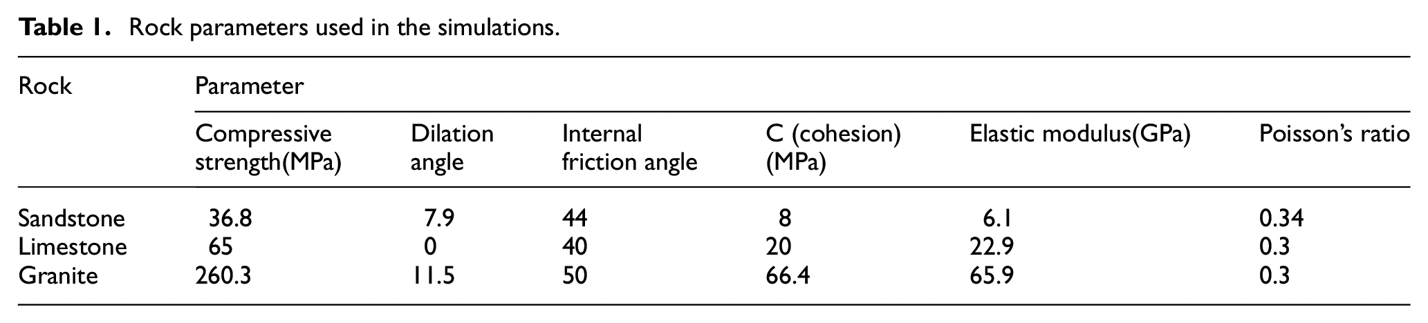
The improved Drucker–Prager model was used for rock material. This model is usually applied to frictional materials such as soil and rocks which have pressure-dependent traits (i.e. material strength rises as pressure increases). Rock materials considered in this study were sandstone with parameters introduced in research by Ord et al. 17 along with granite and limestone with parameters featured in Lu et al. 18 as described in Table 1.
Rock parameters used in the simulations.
Inserts
Insert properties were selected using parameters introduced in Bu et al. 1 with elastic modulus of 600 GPa and Poisson’s ratio of 0.23.
Piston
The piston driving the bit to penetrate rock with repeated blows comprised DIN 1.6580 low-alloy steel, identical to that of the bit body.
Process parameters
Process variables under investigation include insert-bit body fitting interference (0.3, 0.6, 0.9 and 1.2 percent), angle of inclination (0, 22 and 42 degrees) and rock material (sandstone, limestone and granite). The range and interval of the interference values were determined based on the initial investigations (i.e. literature review and screening tests). Wider range of interference was first considered and press-fitting of pins was performed. For smaller values of interferences (e.g. interference of 0.1%), much lower joint strength were obtained, and for larger values of interferences (e.g. interference of 1.5%), visible cracks emerged on the specimen surface. Therefore, the interference fit studies were limited to the mentioned range with equal intervals.
Simulation of bit-rock collision
Single insert
The 3D FEM simulation of bit-rock collision was conducted taking into account the interaction between the insert-body and the rotation of bit. Piston velocity of 10 m/s and rotational velocity of 100 rpm were considered in the simulations. Since rock mass at well bottom extends dimensionally far beyond the model dimensions, displacements of the external planes of the rock model were constrained by applying boundary conditions. Simulations were performed using Abaqus 6.14 FE software. The proposed model is a demonstration of the onset of a drilling process with the time increment of a blow. Thus, the effect of temperature increase on the process was disregarded. However, the moderate rise of temperature in normal conditions (about 100°C) does not exert notable effect. A certain amount of reduced interference of the button inside the body is to be expected as temperature increases, since the coefficient of thermal expansion of steel is greater than that of the tungsten carbide. Effects of air flush and cuttings and debris produced by drilling operations were neglected because they mainly result in bit body wear with little influence on stresses and fatigue life of insert joints. In these simulations, interference was modeled using the interference-fit option of the Abaqus software. In this type of analysis, a certain value of interference is considered in the initial model. Subsequently, this initial interference is eliminated in some defined increments by moving nodes to the equilibrium position, while the process strains and stresses are applied.
DTH drilling bit
After the single-insert condition, the simulation of the process with a 3.5-inch bit was considered. Geometric modeling of this process appears in Figure 2(a). To capture the complexity of the bit geometry, tetrahedral elements with a minimum dimension of 0.4 mm and maximum of 10 mm were specified for the bit body based on the single-insert simulations results. Areas around holes as well as the contact surfaces were meshed using smaller elements (Figure 2(b)). The numbers of elements assigned for rock, each insert, bit body and piston were 416521, 13266, 382546 and 2819, respectively.
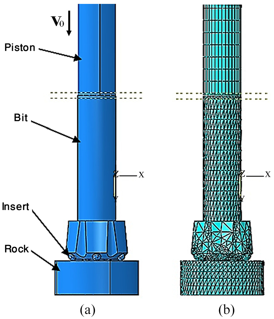
(a) CAD model of the process. (b) FE model after discretization.
Verification of the simulations
Simulation of a pin-hub assembly with dimensions chosen near to those of the present model was considered to verify the accuracy of the simulations. Stress results at the interface and outer diameter of the hub in this assembly were compared with the results of the analytical method (i.e. the Lamé Equation elaborated earlier). Simulation results along with the applied dimensions and parameters are shown in Figure 3(a) and (b), respectively.
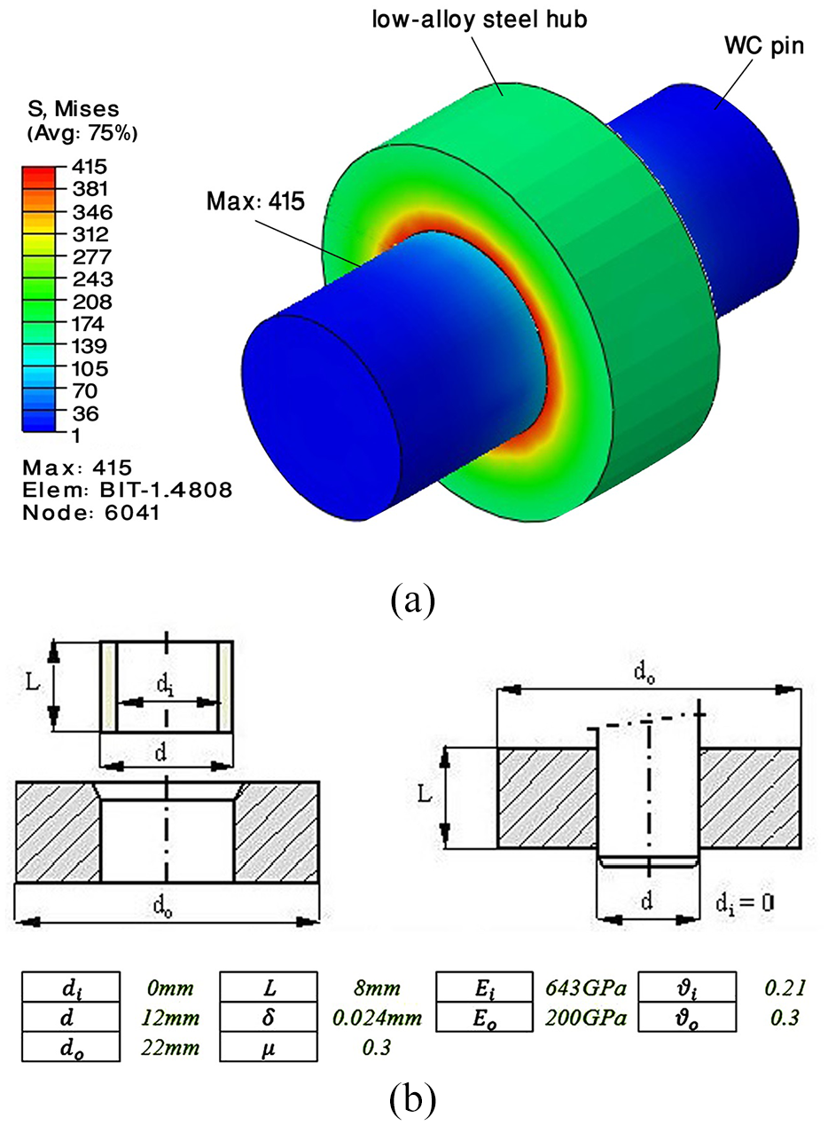
Stress results of the pin-hub interference fit: (a) simulation results. (b) dimensions and parameters.
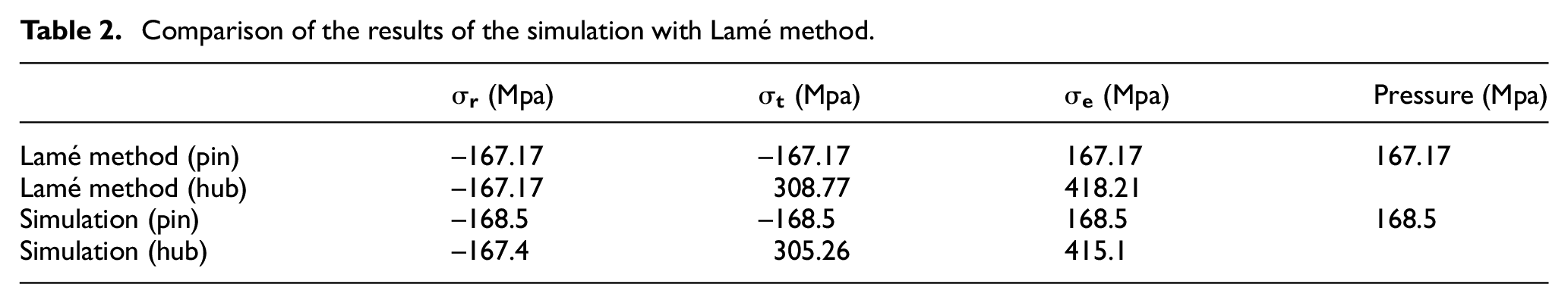
Results of the simulations and analytical method are presented in Table 2. Here,
Comparison of the results of the simulation with Lamé method.
Results and discussion
Fatigue tests
Figure 4 presents force–displacement curves during press fitting of pins (with different interference values) into the fatigue specimens. Forces are increased with pin penetration until the penetration depth reaches the hole width (i.e. width of the specimen). At this point, except for the case with interference of 0.3%, there was a sudden, drastic drop in force before flat-lining at 5–10 kN. This phenomenon results from the plastic deformation of specimens during the initial stages of interference fitting. The greater was the difference between diameters, the greater became the deformation and force. After pin exceeds specimen width, the only retention factor is the sliding friction of contact surfaces. Another important feature seen in these curves is that the force needed to insert (or extract) the pin with interference of 1.2% drops below the case of 0.9%. This arises from excessive plastic deformation and possible damages to the hole surface in the former case. In the case of 0.3%, forces are linearly increased with displacement up to the maximum value, revealing an elastic deformation of the specimen during the insertion process.
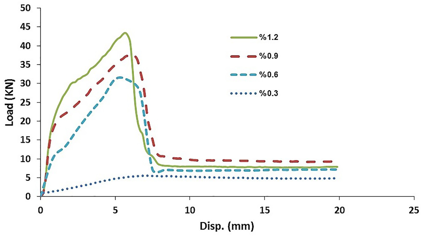
Force–displacement curves during the press-fitting of pins into the fatigue specimens.
Fatigue test results are presented in Figure 5. At first, fatigue life increased with tighter interference. This was because of the work hardening affect along with the compressive residual stresses around the hole as a result of interference. The trend reversed in the case of 1.2% interference with a slight decrease. However, as plastic deformation increased beyond a certain threshold, say 0.9%, small cracks initiated on the specimen surface which limited its fatigue life. It should be noted that in cases with interferences larger than 1.2% (e.g. interference of 1.5%), visible cracks emerged on the specimen surface.
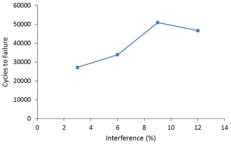
Fatigue test results.
FE simulations
Cross section of the collision process with the angle of inclination set at 42 and the rock type of granite (the most critical setting) and interference of 0.9% is demonstrated in Figure 6(a). Stress distribution in the bit body is shown in Figure 6(b). The stress at the onset of the process was non-uniform near the hole, being greater at thin areas, because of asymmetric geometry of the body. As process progressed, contrary to expectations, stresses did not increase and the stress distribution even grew more uniform. This was because the collision process redistributed stresses to areas of greater thickness, reducing the load in thin areas and at hole-edge locations. However, the residual stresses due to interference fit are high enough to reduce the effect of the stresses resulting from the collision process.
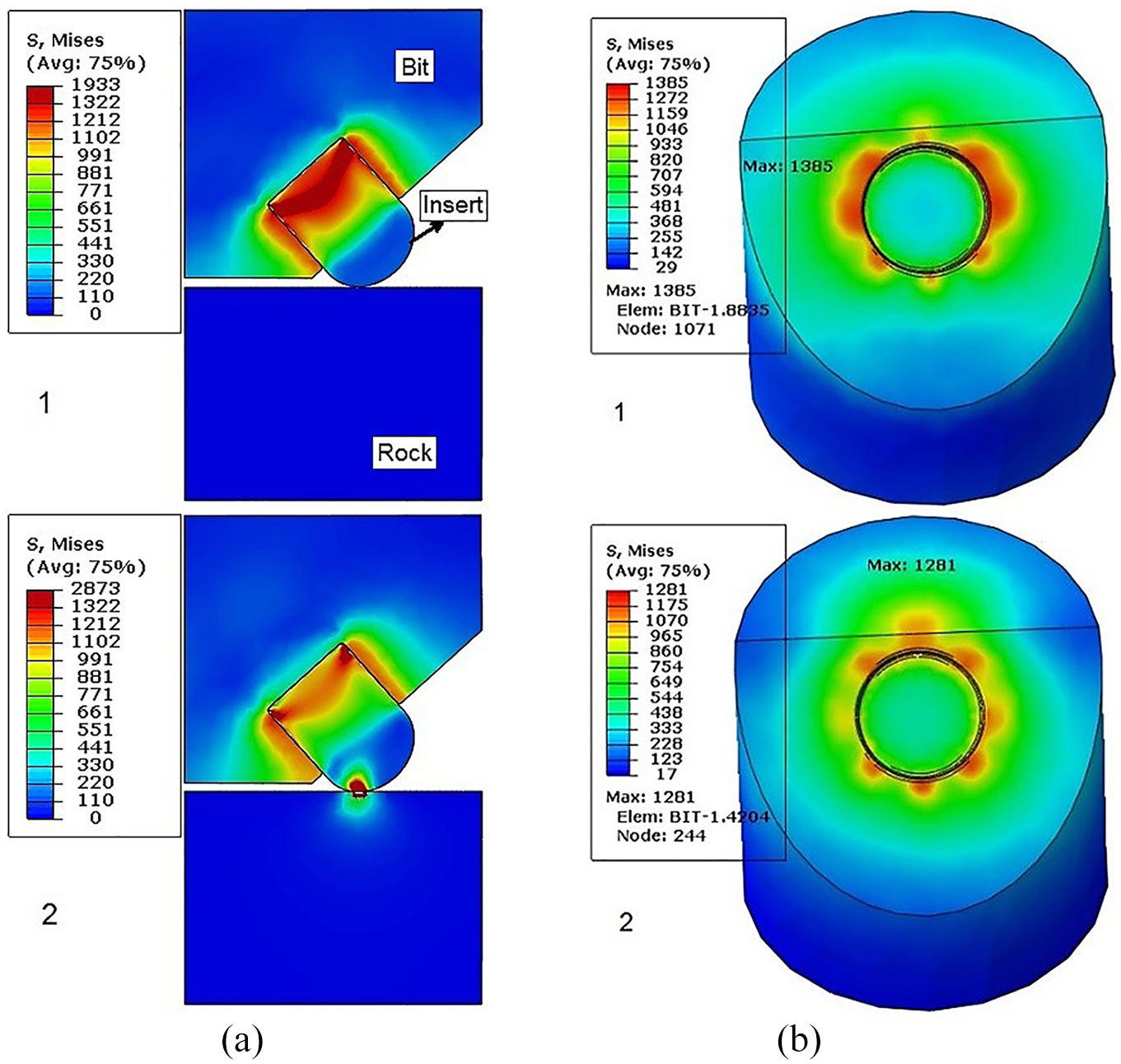
(a) Cross section of bit-rock for 42° inclination and interference of 0.9%: (1) before and (2) after collision. (b) Stresses in bit body: (1) beginning of the process and (2) at t = 0.004s (corresponding to maximum force).
The bit-rock collisions fixed at the 42° inclination with various interferences were next run. The stresses created at the point of collision were similar to those of 0.9% interference, but the stresses of the bit body were different. Although the stress levels are reduced with looser interference, the stress distribution for interference of 0.3% grew more uneven as a result of impact and rotation. In the case of 1.2% interference, the stresses almost reached the ultimate strength of the material right from the onset, making the bit body prone to failure. The process with inclination angle of 22 exhibited the same manner as 42, with lower stress magnitudes and non-uniformity which confirms higher sensitivity of the 42 inclination. To further investigate the process, forces applied to the bit during collision were analyzed. Figure 7 shows thrust and lateral forces for selected angles. Force values were independent of interference. Lateral forces (Fy) generated by the rotary motion developed significant shear stresses (which remarkably influences the rate of penetration and drilling speed). Although slightly greater, the thrust component (Fz) peaked for the 22 degree mode. On the other hand, the onset slope of the zero-degree mode steepened and its fluctuations exceeded since rock failure occurred earlier in this case because of the orthogonality as well as more rapid dissipation of impact energy.
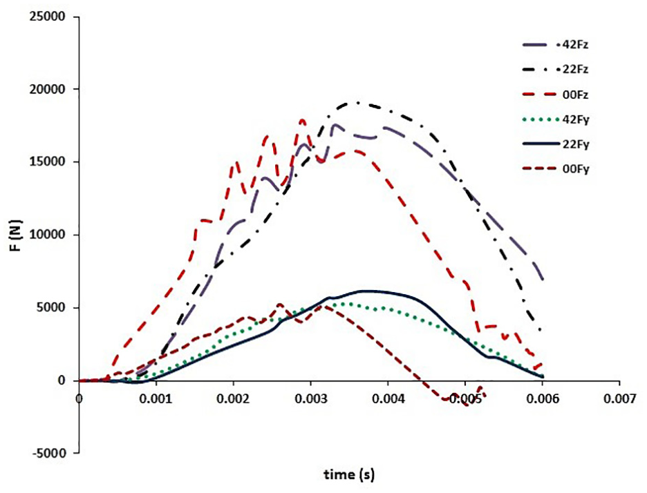
Drilling bit forces.
Displacement–time (penetration) curves for various rocks were also investigated. For higher strength of granite, the bit initially penetrated the rock and then retracted partially. However, in softer rocks of limestone and sandstone, the bit penetrated deeper throughout the process. Thus, drilling efficiency can be enhanced using lower impact energies for softer rocks. Stress distribution in a commercial 3.5-inch bit with interference of 0.9% is shown in Figure 8. Maximum stresses emerged at bit-insert contact areas and around the holes because of the presence of interference and resultant strains. This phenomenon, striking mainly around the central holes, is primarily owing to stress superposition effects. This was confirmed by contact pressure study as it showed that contact pressure distribution was almost the same in all the holes surfaces. Similar to the single-insert condition, stresses were decreased slightly when collision commenced. However, the equivalent stresses around adjacent inserts were higher because of superposition of stresses.
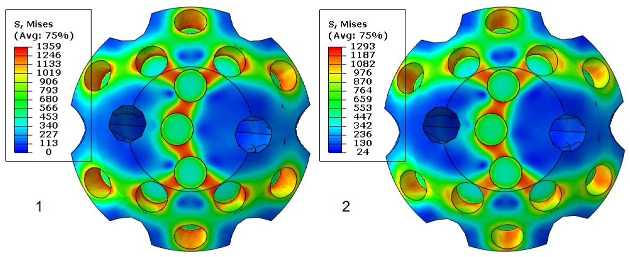
Stress distribution in drilling bit at (1) onset and (2) t = 0.004s (peak force).
Site tests
The designed drilling bit was then manufactured based on the results of fatigue tests and FE simulations. Insert holes were machined precisely with dimensions and tolerances leading to interferences of 0.6% to 0.9%, and then tungsten carbide inserts were press-fitted into the holes. Machining of holes consisted of a drilling process before hardening the bit body and a precision hard-machining to the mentioned tolerances after hardening. The manufactured bit is shown in Figure 9.
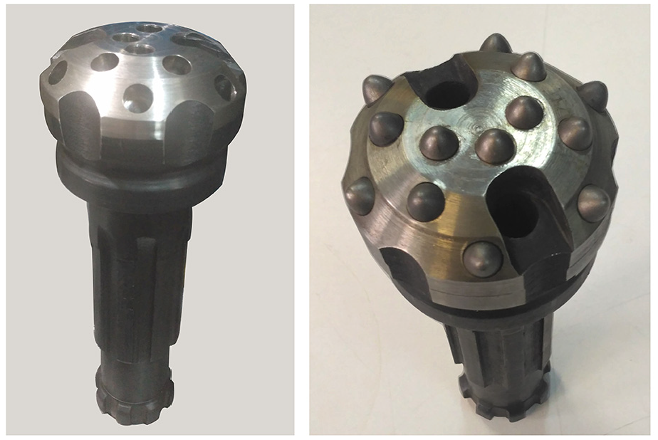
Manufactured bit, left: before and right: after fitting the inserts.
To evaluate the performance of the bit, a number of site tests in practical drilling conditions were carried out at the request of a drilling company. The practical parameters applied for these tests are common for such a drilling condition (the drilling parameters considered in this study were almost identical too). These parameters are presented in Table 3. These tests were performed using a Furukawa drilling machine at a drilling site in Tehran. In these tests, a total number of 5 wells of 6 meters depth were drilled in one day at the rate of penetration (ROP) of about 0.5 m/min. Then, 12 wells of 6-meters depth were drilled in another day. Figure 10 shows the bit after about 30 and 102 meters of drilling. The drilling tests were quite successful, and the bit performed well.
Site tests parameters.
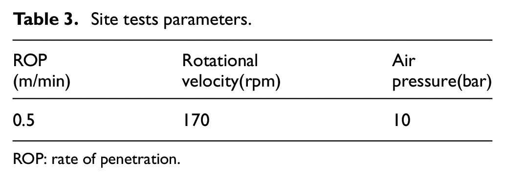
ROP: rate of penetration.
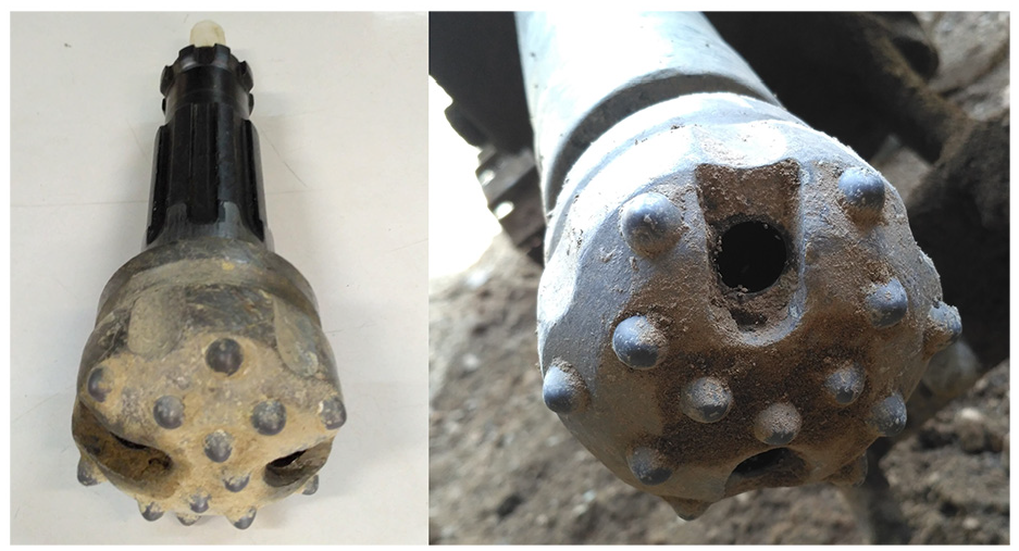
Manufactured bit, right: after drilling about 30 meters and left: after drilling about 102 meters.
Conclusion
The present study demonstrated that the inserting (or extracting) forces of pin-hole assembly increased and fatigue life of the specimens lengthened with tighter interferences because of resultant work-hardening and compressive residual stresses. This attitude was observed until a specific value of interference. Stemmed from cracks in the hole surface, as the interference increased to more than 0.9%, a slight decrease occurred in both fatigue life and sliding force of fitting process. Furthermore, a certain amount of plastic strain would improve the fatigue life of the interference joint. Increasing inclination angle makes it more critical owing to higher stresses developed by lateral forces and lower local thickness of the bit body. On the other hand, maximum stresses were obtained in the areas around the holes close to each other. This advises an important parameter that can help obtaining the optimum distance and pattern of the inserts on the bit. Stress distribution in the bit body is less dependent of the impact forces in high interference values. Results of the study presented here would greatly assist the designers in determining the interference fit manufacturing tolerances.
Footnotes
Appendix 1
Declaration of conflicting interests
The author(s) declared no potential conflicts of interest with respect to the research, authorship, and/or publication of this article.
Funding
The author(s) received no financial support for the research, authorship, and/or publication of this article.