
Abstract
To solve core problems of slow arc response and unstable combustion, arc movement characteristics and arc action rules in short electrical arc milling are studied using a high-speed acquisition system and the Phantom high-speed camera in this article. To improve arc reignition, the characteristic parameters of arc discharge are determined as a discharge gap of 0.053 mm and discharge time of 2180 μs. A short electrical arc milling experiment with nickel-based superalloy GH4169 is carried out, confirming that the continuous stable discharge of the arc can easily produce a material removal rate of 40 g/min and a tool wear ratio of 0.8%. An SU8010 scanning electron microscope and energy spectrum analyzer are then used to study the erosion mechanism of GH4169 in short electrical arc milling. This article aims to expand the processing range of short electrical arc machining in the field of special material processing to provide experimental and theoretical bases for the development of short electrical arc milling technology theory and methods.
Introduction
Short electrical arc (SEA) turning machining effectively solves processing-related technical problems associated with hard materials such as large rolls, grinding rolls, and casings. The process provides numerous advantages including high removal efficiency and continuous discharge, which are important technical features for the efficient processing of refractory conductive materials. As such, SEA is widely used in metallurgy, agricultural equipment, and petrochemicals.1–4 In the turning process of the fatigue layer of roll parts, the removal efficiency is 1.92 × 105 mm3/min, which is 10 times that of anode machining (1.8 × 104 mm3/min) and 15 times that of high-efficiency dry electric discharge machining (dry EDM, 1.23 × 104 mm3/min). The SEA milling process can be effectively combined with the traditional processing technology, and its application scope and high efficiency are more obvious. It is the development and supplement of traditional milling technology, and is the conventional application of unconventional technology.5,6 To expand the application of SEA milling technology, scholars have conducted research into optimization of the electric spindle, pulse power supply, and processing technology.7–11 However, experimental results have not yet achieved the desired effects. As the SEA discharge channel is extremely narrow, the working medium contains insufficient energy to be injected, the arc cannot burn stably, and the electrode surface can be severely ablated. This causes the accumulation of a large amount of molten material, along with frequent short-circuiting, arcing, and excessive combustion. These problems present major limitations to the application of SEA milling.
To visualize the discharge gap in the electrical processing field, several researchers have focused on the erosion process using advanced equipment and technology. Kitamura et al. 12 used silicon carbide (SiC) as the electrode material to observe microscopic phenomena of the EDM process via high-speed camera. Upon analyzing the gap discharge distribution, debris particle distribution, bubble distribution, and bubble size, results showed that more than 70% of working surfaces were occupied by bubbles after hundreds of pulsed discharge machining instances. Miyajima et al. 13 observed a machining gap after continuous pulse discharge by inserting transparent plastic disks into annular metal electrodes, finding that even when immersed in a liquid medium, most of the machining gap was still occupied by bubbles. Hayakawa et al. 14 used a polymethyl methacrylate (PMMA) plate as an electrode and a high-speed camera to observe the trajectory of debris particles scattered from the discharge point as well as bubble expansion and contraction. The results showed that the discharge duration varied from 60 to 1000 μs, and the material was removed when the bubble expanded or ejection pressure reduced. Zhao and Han 15 developed experimental equipment to observe the movement process of etched particles and bubbles. It was determined that many bubbles were generated during the discharge process, most of which were connected during discharge before expanding rapidly and pushing most etched particles to the edge of the bottom gap. Mullya and Karthikeyan 16 analyzed the fluid flow along the narrow gap of micro-electro-discharge-milling process for different machining conditions by computational fluid dynamics simulation, and the effect of different sized particles formed at various positions and their subsequent movement was also analyzed by particle simulation. The results showed that the average velocity of the fluid in the gap was affected by the change in the inlet nozzle velocity, and the eddies were created due to the change fluid pattern. Eddies provided fresh dielectric in the gap and removed debris particles from the gap. The non-uniform redeposition was observed on the milled surface which was due to the rotation of the electrode, the variation of fluid velocity in the gap, and formation of eddies.
Short electrical arc machining (SEAM) is a new electro-machining method with strong flame current, electron current, ion current, and arc current. It also belongs to the field of electro-machining technology in the special machining industry. Using SEAM, the discharge channel between the tool and the workpiece exhibits a clear arc effect, especially under water jet compression, producing stronger thermal compression and causing the surface material to be quickly melted and stripped off the matrix. To explore the basic physical processes involved in SEA milling, the Phantom high-speed camera is used in this study to capture the dynamic process of SEA discharge to obtain the arc shape change law and discharge characteristic parameters. An SEA milling experiment using nickel-based superalloy GH4169 is then performed. The results provide theoretical support for the efficient removal of nickel-based alloys in SEAM, as well as process optimization.
Experimental preparation
Experimental principle
SEA is a type of discharge state between an electric spark and arc with a millisecond pulse width. The SEAM electrical machining method uses the excited arc discharge group or discharge group mixed with spark discharge generated between two electrodes to remove metal or non-metal conductive materials. This is carried out under the action of mixture working medium with a certain proportion of gas, liquid, and pressure. The SEAM process is predominantly used for high-productivity processing of various types of cement grinding rollers, vertical grinding rollers, slurry pump impellers, large cold-rolled work rolls, high-speed wire rolls, and other large workpieces with difficult to process metal materials. At present, SEAM is successfully applied in the aerospace industry, and can quickly process aero engine honeycombs with a diameter of less than 1250 mm with low stress and high efficiency. The efficiency of SEAM is more than five times higher than that of EDM, and the thickness of the surface remelted layer is 0.009–0.041 mm. Therefore, SEAM and equipment application market are facing a situation of full start.
In SEAM, a voltage is applied between the workpiece and tool (the breakdown voltage is lower than the spark discharge), and the working medium is broken down to form a drum discharge channel. The size of the cathode and anode areas differs and the current density also varies. The anode current density is approximately 2800 A/cm2 and the cathode current density is 300 A/cm2. During the machining process, the arc moves, elongates, or bends rapidly under the action of a gas or liquid, and nearly the entire current flows through the arc column. In the SEA discharge channel, charged electrons collide with the high-speed particle motion, converting electric energy into heat energy to form a high-temperature heat source on the electrode surface. The surface discharge area is rapidly heated and the workpiece material is melted and vaporized away from the electrode surface. A physical model of SEA pulse discharge is provided in Figure 1.
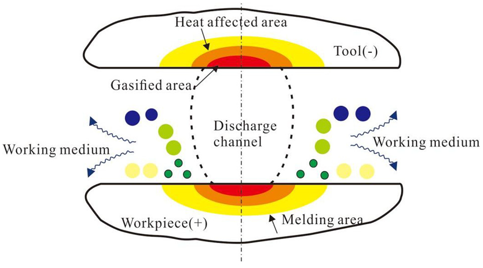
Physical model of SEA pulse discharge.
Experimental materials
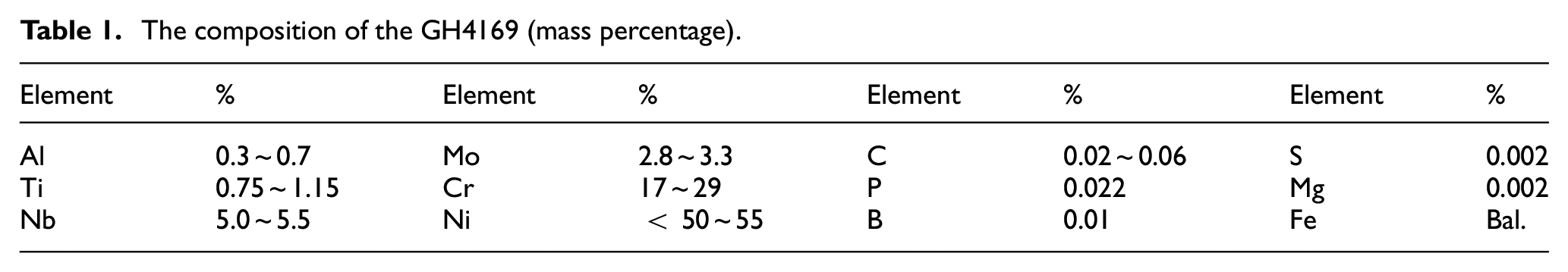
Nickel-based superalloy GH4169 is a typical difficult-to-machine hard-face material. It contains a large number of high melting alloy elements, including carbides and nitrides, and can maintain good strength, hardness, oxidation resistance, heat resistance, corrosion resistance, and fracture toughness within a certain temperature range. As such, the alloy is mainly used for key components of aerospace engines and nuclear reactors in high-temperature environments. Due to the low thermal conductivity and poor processability of nickel-based alloys, numerous problems—including large cutting force, cutting temperature, and severe tool wear—are encountered in the machining process.17–19 For this type of superhard and difficult-to-machine material, SEAM provides a technical solution. Tungsten–copper (W–Cu) alloy is often used to process superhard metal materials because of its relatively small loss, high processing speed, and processing quality. The material composition of the GH4169 selected in this article is shown in Table 1. The W–Cu alloy employed in the experiment is obtained by powder metallurgy, in which the Cu content is 30%.
The composition of the GH4169 (mass percentage).
Experimental condition
The SEA milling experiment was conducted using a five-axis computerized numerical control (CNC) machine tool with a maximum axial travel of 650 mm for X, 400 mm for Y, 500 mm for Z, 360° for A, and 90° for C. The SEA discharge process was collected using a high-speed camera in real time. The frame frequency, resolution, exposure, and other parameters were set using the image acquisition software Sim-V660-0. The working distance of the lens was 2 m and the trigger point was the follow-up trigger. The image acquisition system is shown in Figure 2. A laser scanning confocal microscope (LEXT; OLS4000) was used to carry out non-destructive three-dimensional (3D) observation and measurement, scanning electron microscope (SEM; SU8010) was employed to obtain the surface morphology of the electrode, and energy-dispersive X-ray spectroscopy (EDS) was used to analyze the electrode end face. Before observing the specimen, the following process was performed: first, specimens were cut to a size of 10 mm × 10 mm × 6 mm using wire cut EDM. Metallographic examination of the specimens was then milled by progressive-grade SiC papers, and finally, a polished mirror was obtained using diamond plaster. To observe the metallographic structure of samples, it was necessary to use a small amount of aqua regia for 10 s. To explore the motion characteristics and removal mechanism of the continuous arc in SEA high-efficiency milling, reasonable processing parameters were selected according to many previous process experiments and are listed in Table 2.
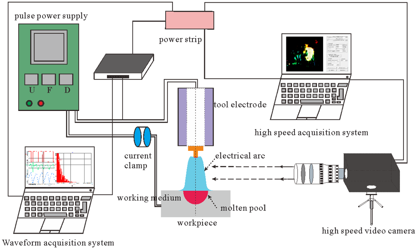
The image acquisition system.
The machining parameters in SEA milling.
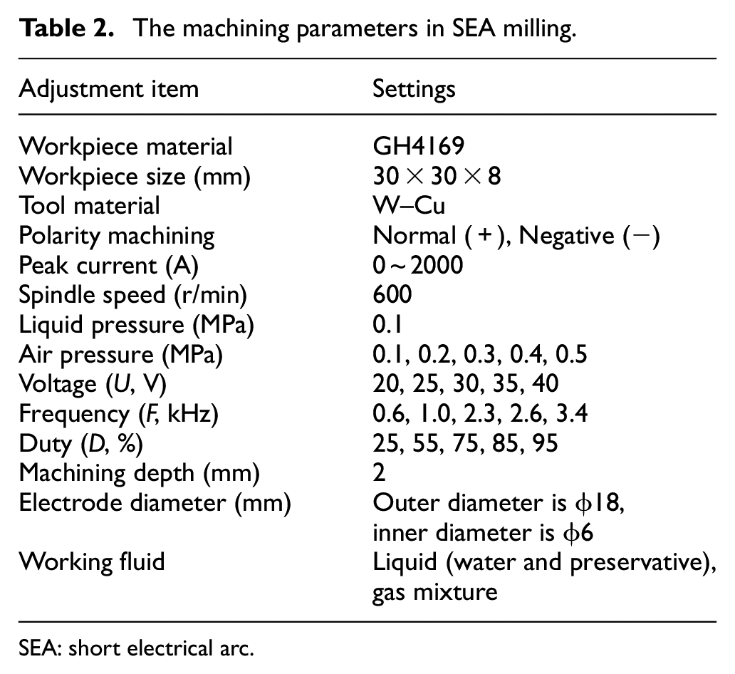
SEA: short electrical arc.
Discharge process
Electrical signal
Electric signals collected by the high-speed acquisition system in SEA milling are used to represent the mechanical effects of arc discharge (see Figure 3). Due to the continuous action of high-frequency voltage arcing, the current rapidly increases to the peak current, reaching a maximum of 500 A, the voltage gradually decreases to maintain voltage, and the power supply switches from the constant voltage output mode to the steady current output mode. The current rises and falls in one cycle that is stable in the range of 200–500 A and can achieve stable arc processing. When the arc is extinguished, the power supply automatically switches to constant voltage to quickly trigger the arc again. The maximum gap voltage is 28.28 A, which is greater than the power supply voltage. This indicates that the solid particles dispersed in the working medium must be polarized in the electric field between the poles. The constrained electric field and the external electric field are superimposed according to certain rules, resulting in the channel being in the shape of a waist drum. As illustrated in Figure 3(b), as the arc current increases, the arc voltage decreases, indicating that the arc is a load in the circuit with reduced volt-ampere characteristics.
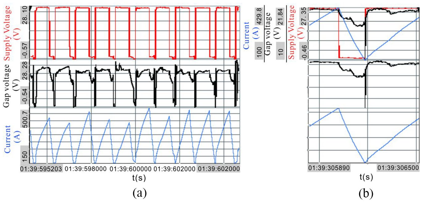
Electrical signal in SEA milling: (a) continuous arc discharge waveform and (b) instantaneous arc discharge waveform.
Discharge characteristics
Volt-ampere characteristic of arc
Different discharge states were counted 200 times, and voltage volt-ampere characteristics were obtained using the average voltage value and the average current value as the measurement type (see Figure 4). In the experiment, the average voltage of the arc declines with an increase in the current. The discharge point is mainly concentrated between 20 and 22 V and an average current of 200–500 A, reflecting the specialty of a low voltage and high current in SEA milling. In addition, after the gap voltage breaks down the medium, the gap conductivity instantaneously and rapidly rises, such that voltage that is nearly in an open state quickly drops as the current rises. Due to this process, the volt-ampere characteristic curve at the initial stage of arc generation exhibits a significant downward trend and then becomes gentle.
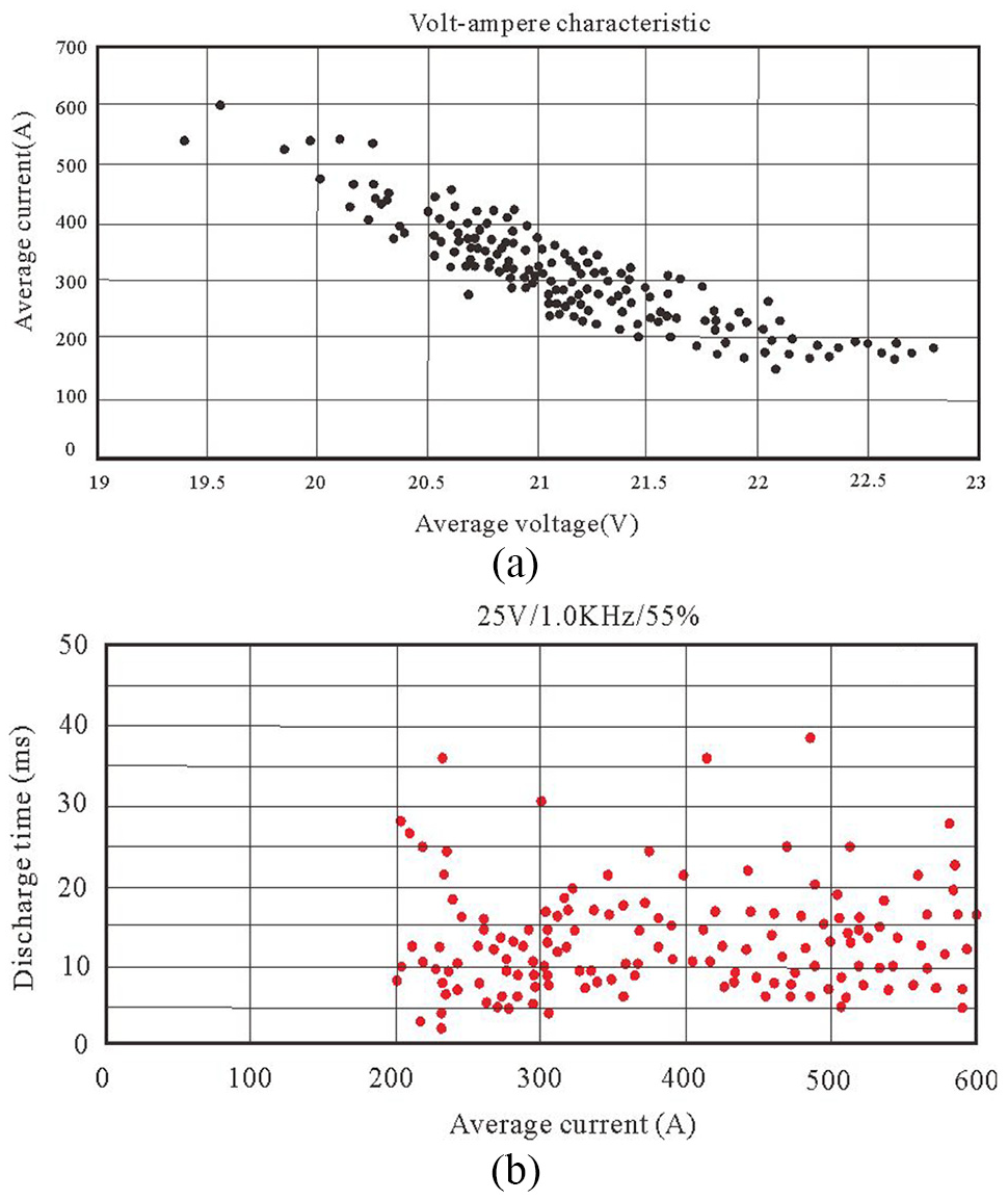
Discharge characteristics: (a) average voltage and (b) average current.
Polarity processing
Volt-ampere characteristics of the arc are different under different processing polarities. In Figure 5(a), the arc discharge is relatively stable without the arc-cut phenomenon, and a single discharge within one pulse width is completed under normal polarity processing. The gap voltage declines and fluctuates within the range of 15–20 V, the peak current reaches 600 A, and the arc discharge is relatively continuous. In Figure 5(b), arc-cut and secondary discharge phenomena occasionally occur under negative polarity processing. The gap voltage declines and fluctuates within the range of 10–15 V, and the peak current reaches 220 A.
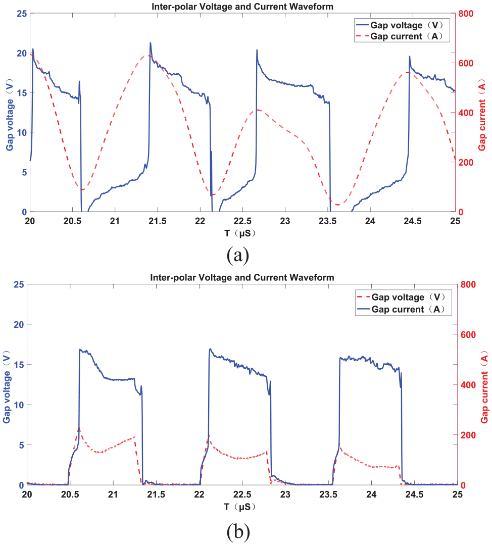
Interpolar voltage–current waveform at different polarities: (a) normal (+) and (b) negative (−).
In normal polarity processing, the kinetic energy of the positive ion bombardment tool electrode is smaller, as is the heat energy of conversion. Electrode loss only occurs at the outer end of the bottom of the electrode. As illustrated in Figure 6(a), defects such as droplets, cracks, and porosity on the workpiece surface are clearly reduced, and the amount of defects is low. In negative polarity processing, converted thermal energy increases significantly, resulting in greater axial electrode loss that cannot produce stable processing. Typically, the specimen has not been processed yet, and serious electrode loss causes the discharge gap to be larger than the maximum arc generation, resulting in arcing cut and processing interruption. This causes defects on the workpiece surface to increase significantly. Therefore, to render the arc discharge stable, normal polarity processing is generally used.
The machining effect at different polarities: (a) normal (+) and (b) negative (−).
Arc shape
Visualization of arc shape
The machining process in SEA milling evolves from multi-stage dynamic changes, including arc ignition-combustion, establishment of a discharge channel, melting and gasification of electrode materials, and deionization of the medium. After the SEA discharge channel is established, a cathode region, an anode region, and an arc column region are formed. The arc column region is essentially the area where the plasma experiences thermal dissociation, as shown in Figure 7. The GH4169 is locally melted and gasified by the SEA to generate metal debris. These debris are detonated under the action of the working medium, and most of the detonated material is spherical molten metal particles. A large amount of arc light is generated between the poles, the largest part of the light intensity is the arc column, and the small spot is the metal debris that exploded from the base metal. The marking part is the melt formed by the melting of the workpiece material due to the local instantaneous high temperature of the arc. The melt is then blasted off the workpiece by the action of gravity and the blowing force of the working medium.
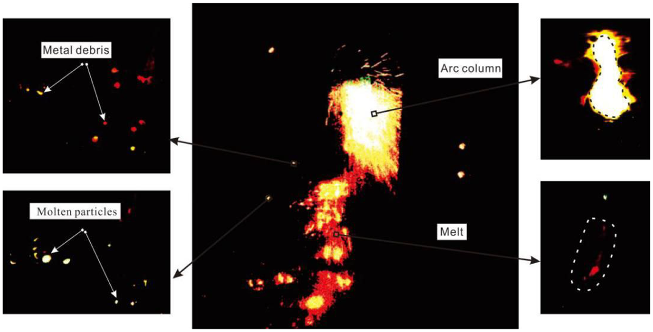
The visualization of arc shape.
The dynamic change process of SEA milling is illustrated in Figure 8. When the discharge gap between the workpiece and the tool is the smallest, the arc is released. Arc plasma expands in a few microseconds, and a discharge channel is established after dielectric breakdown. A luminous region appears between the interpolar region at 5 μs, and its brightness is continuously enhanced within 5–15 μs. During this period, the arc plasma experiences thermal expansion, the workpiece material melts and is gasified instantly, and a large amount of substances and debris explode between the poles. These materials are mostly spherical solid molten particles and spherical working droplets (see Figure 7). Under surface tension and high pressure, molten particles continue to expand and explode. The working liquid droplets diffuse around detonation at the explosion point and increasingly expand in volume. The molten particles are completely thrown out around 18 μs, at which time the interpolar gap becomes larger. When the interpolar gap is larger than the discharge gap at 20 and 23 μs, the discharge channel gradually begins to disintegrate. The arc is then extinguished at 25 μs and the discharge channel disintegrates completely.
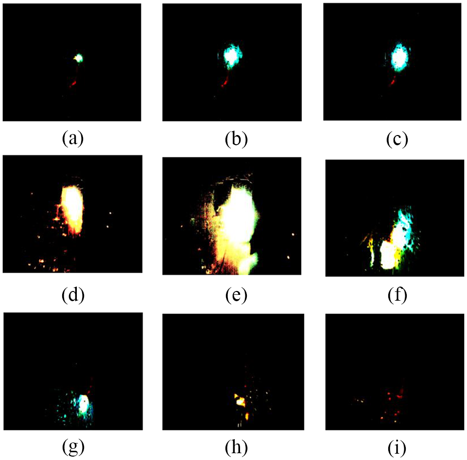
The arc discharge dynamic process: (a) 5 μs, (b) 7 μs, (c) 10 μs, (d) 12 μs, (e)15 μs, (f) 18 μs, (g) 20 μs, (h) 23 μs, and (i) 25 μs.
Arc shapes at different peak currents
The arc shapes at different peak currents are shown in Figure 9. The arc shape gradually transforms into a long pear shape and the arc length increases with a rise in the peak current. The range covering the anode region gradually widens and expands to the periphery. Therefore, the peak current is determined to be an important factor affecting arc shape. When the peak current reaches 200 A, the arc shape resembles an ellipse and a bright spot marks the arc column region. When the peak current reaches 600 A, the arc shape deflects, elongates, and gradually diverges.
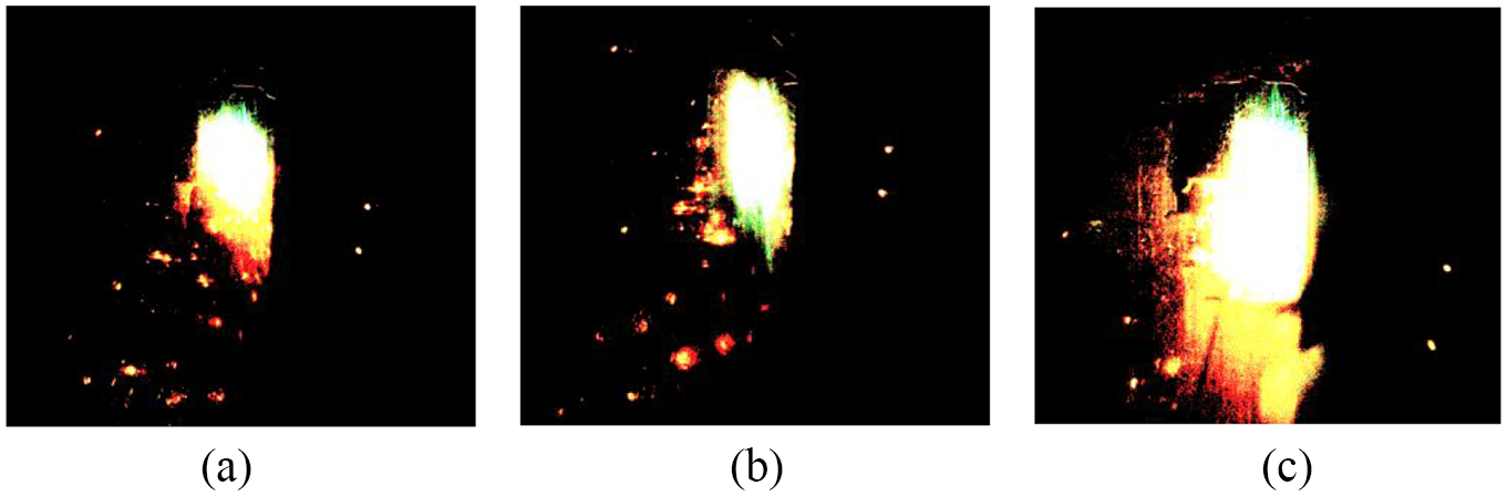
Arc shapes at different peak currents: (a) 200 A, (b) 400 A, and (c) 600 A.
Discharge characteristic parameters
Discharge gap
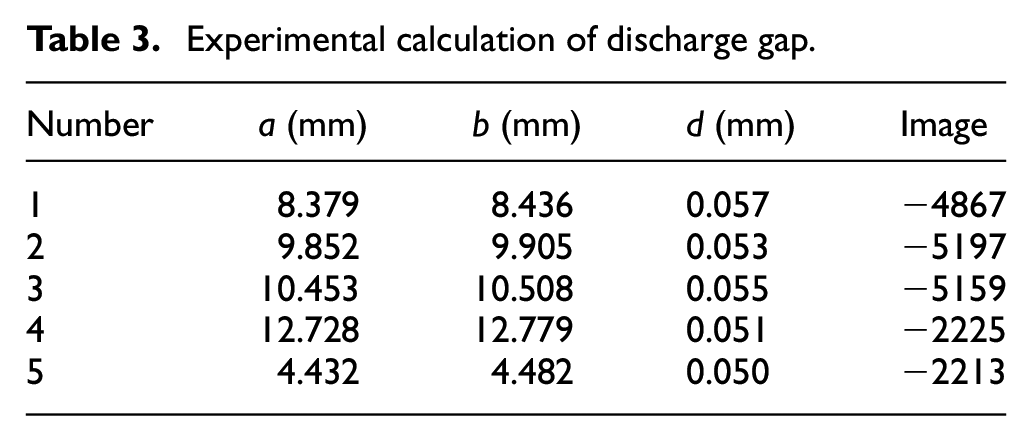
In the experiment, the measurement unit was set to mm in the Sim-V660-0-0 image acquisition control system, the measurement amplitude was determined in the system, and reference origin O was used to obtain the abscissa of discharge channel endpoints a and b. The discharge gap in SEA milling was calculated using the formula d = b − a. To reduce experimental error, five sets of coordinate values were selected, with measured and calculated values listed in Table 3. The average value of five groups of data was
Experimental calculation of discharge gap.
Discharge time
Two videos recorded with a high-speed camera were extracted and five groups of data were selected to calculate the discharge time. The calculation process was as follows: (1) the arc discharge range was estimated to be 2000–2500 μs; (2) an abscissa was set where the discharge light spot was stronger; and (3) the video was played manually at the rate of one frame and the appearance time and disappearance time of the light spot on the abscissa were recorded. The difference value between the two times denoted the SEA milling discharge time. On the basis of the above steps, measured groups of data are shown in Table 4.
Experimental calculation of discharge time.
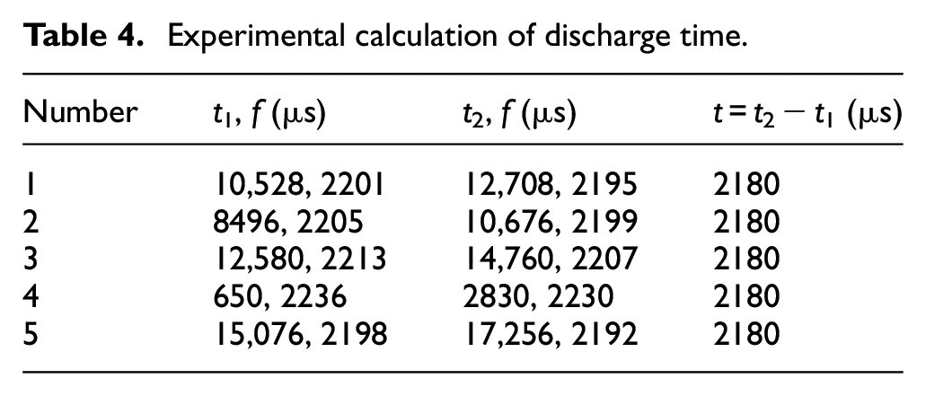
The first three sets of data are taken from the first video and the last two are from the second video. Taking data of the first group from the first video as an example, when the trigger records frame 2195, the channel begins to ignite. When the subsequent trigger records frame 2201, the channel arc is extinguished. Table 4 indicates that the time from arcing to arc extinguishing in each group of data is 2180 μs, revealing that the time is fixed from the establishment of the discharge channel to the end of deionization. Thus, another characteristic parameter in SEA milling is determined to be discharge time.
Experimental analysis of GH4169 in SEA milling
Surface roughness
When the arc discharge sustaining time is equal to the duration of the pulse power supply, the charged particles in the channel move sufficiently, the surface material of the workpiece can be completely eroded, and a series of complete discharged pits are formed on the workpiece surface. When the duration of the arc discharge is shorter than the duration of the pulse power supply, the charged particles in the channel do not move sufficiently, part of the workpiece material is eroded, and some tiny discharge pits are formed. The size of micro type discharge pit is smaller than that of the complete discharge pit. Therefore, the surface of the workpiece after SEA milling is formed by the superposition of numerous irregular discharge pits, and the surface roughness of the workpiece depends on the distribution and size of the discharge pits.
The 3D surface topography was observed under different processing parameters, and arithmetic mean height, root mean square height, and maximum peak height (Sa, Sq, and Sp) were selected to describe functional characteristics of the machined surface, as shown in Figure 10. According to the observations, the workpiece surface is superposed by an infinite number of irregular electric etched pits, surface peaks become more regular, and vertices are either spherical or ellipsoidal. An increase in the peak current causes the single pulse energy to increase, and the size and shape characteristics of the peaks change more drastically, thereby increasing their influence on the surface roughness. When the pulse width increases, the melting depth of the material, the corresponding depth of the discharge pit, and the surface roughness all increase. However, the pulse width has a smaller effect on the depth of the discharge pit than the peak current. The machined surface roughness is proportional to the arc energy and the surface roughness can be reduced by changing the electrical parameters.
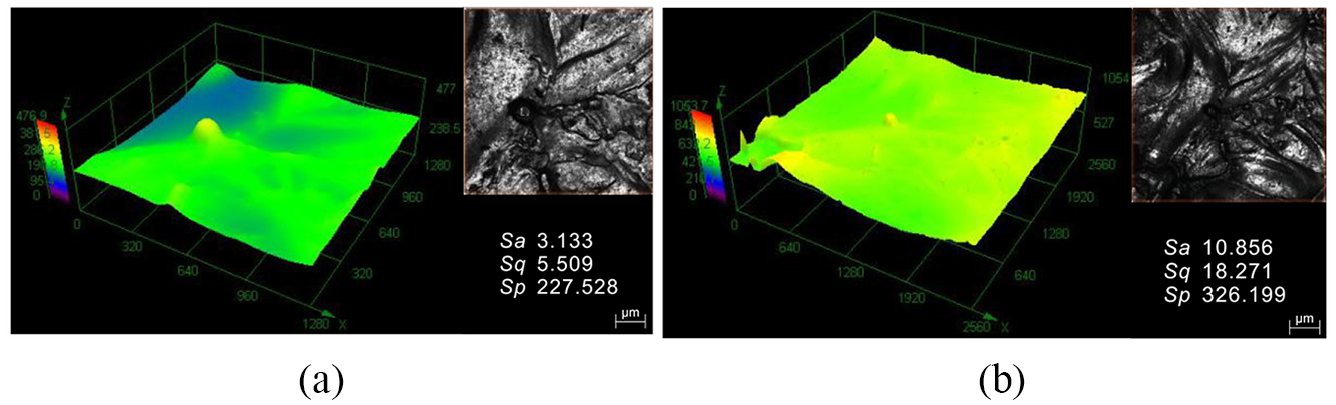
Surface roughness: (a) (U = 25 V, F = 2.3 kHz, D = 55%) and (b) (U = 30 V, F = 2.3 kHz, D = 75%).
Material removal rate and tool wear ratio
The experiment was carried out under different U, F, D, and P using material removal rate (MRR) and tool wear ratio (TWR) as evaluation indices, as shown in Figure 11. When F = 1 kHz, D = 55%, and P = 0.3 MPa, the MRR increases with a rise in U, and the TWR decreases first and then increases with a rise in U. The maximum MRR is 20 g/min and the minimum TWR is 0.8% at a U of 40 V. With the increase in discharge energy input, the energy density of arc plasma increases significantly, and the process of heating, melting, and gasification of workpiece materials intensifies, resulting in a sharp increase of material quality eroded by single pulse arc discharge. In addition, the high melting point of W–Cu electrode and the cooling effect of high-speed flushing are beneficial to reduce electrode loss. When U = 25 V, D = 55%, and P = 0.3 MPa, the MRR changes only slightly with an increase in F, while TWR increases significantly with an increase in F. The MRR is maintained at 18 g/min and TWR changes in the range of 0.85%–1.8%. This is because the arc discharge point is concentrated, causing electric field distortion at the edge and sharp corners of the electrodes and continuous discharge combustion at the maximum field strength, resulting in an increase in TWR.
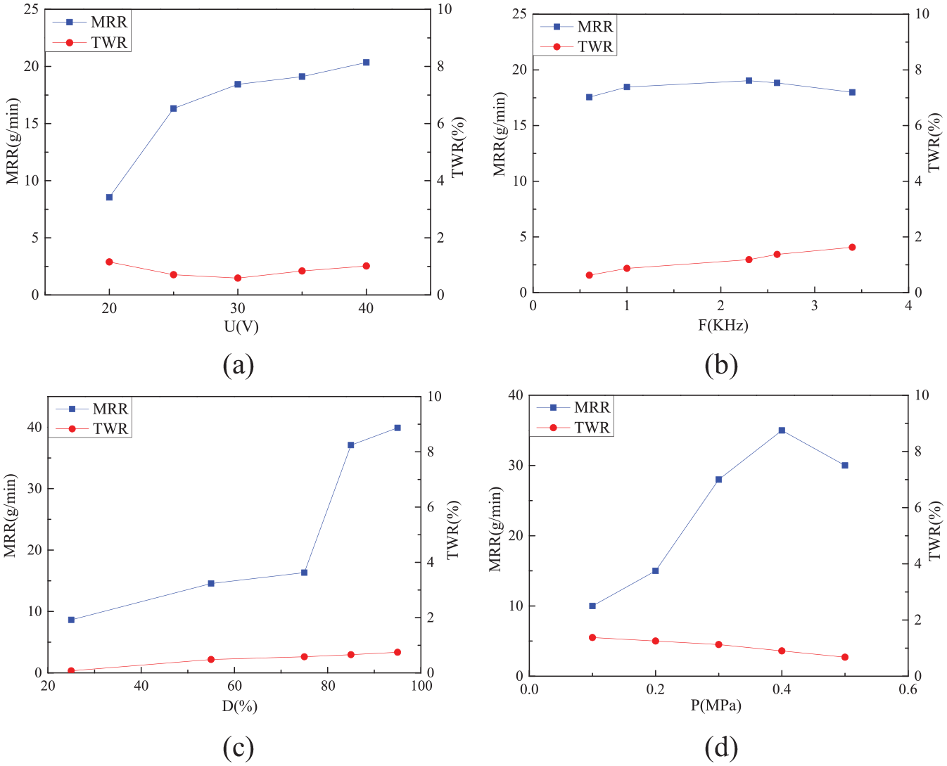
The MRR and TWR curves: (a) U, (b) F, (c) D, and (d) P.
When U = 25 V, F = 1 kHz, and P = 0.3 MPa, the MRR and TWR rise with an increase in D, and the variation range increases significantly. The maximum MRR is 40 g/min at a D of 85%. When the discharge period is a constant, the effective discharge rate of arc machining can be maintained at a high level, resulting in an improvement of the MRR and TWR. The P is closely related to the ejection of molten material and dissipation of residual heat. When U = 25 V, F = 1 kHz, and D = 55%, the dielectric facilitates elimination of ionization with a rise in P, resulting in an increasing MRR. The maximum MRR reaches 35 g/min at a P of 0.4 MPa. However, when P increases to a certain extent, particles accumulate in the side gap, resulting in a lower MRR. The TWR declines with an increase in P because an increase in the fluid flow rate can also produce an obvious cooling effect and reduce electrode loss.
In summary, SEA milling is highly suitable for large-scale roughing of difficult-to-cut materials such as nickel-based superalloys. Using W–Cu alloy as an electrode material, the maximum MRR is 40 g/min, and the lowest TWR can be controlled within 1%.
Micromorphology of the workpiece surface
The micromorphology of the workpiece surface is obtained using SEM (U = 25 V, D = 55%, F = 2.3 kHz). Surface defects that cause SEA heat release are mainly droplets, pits, porosity, cracks, recast layer, and electric erosion products, as shown in Figure 12(a) and (b). In Figure 12(c), due to the thermal erosion of the arc and the strong flushing of the working medium, some of the material is resolidified on the workpiece surface to produce a recast layer, and the lower portion of the recast layer continues to be thermally eroded by the arc to form a heat-affected layer. The metallographic structure, chemical composition, and mechanical properties in the heat-affected zone change, resulting in residual stress on the workpiece surface which produces microcracking. In Figure 12(d), most etched particles are spherical. The particle size and distribution can also reduce the breakdown force of the arc discharge, which affects the discharge position and the machining gap, resulting in a substantial change in discharge state.
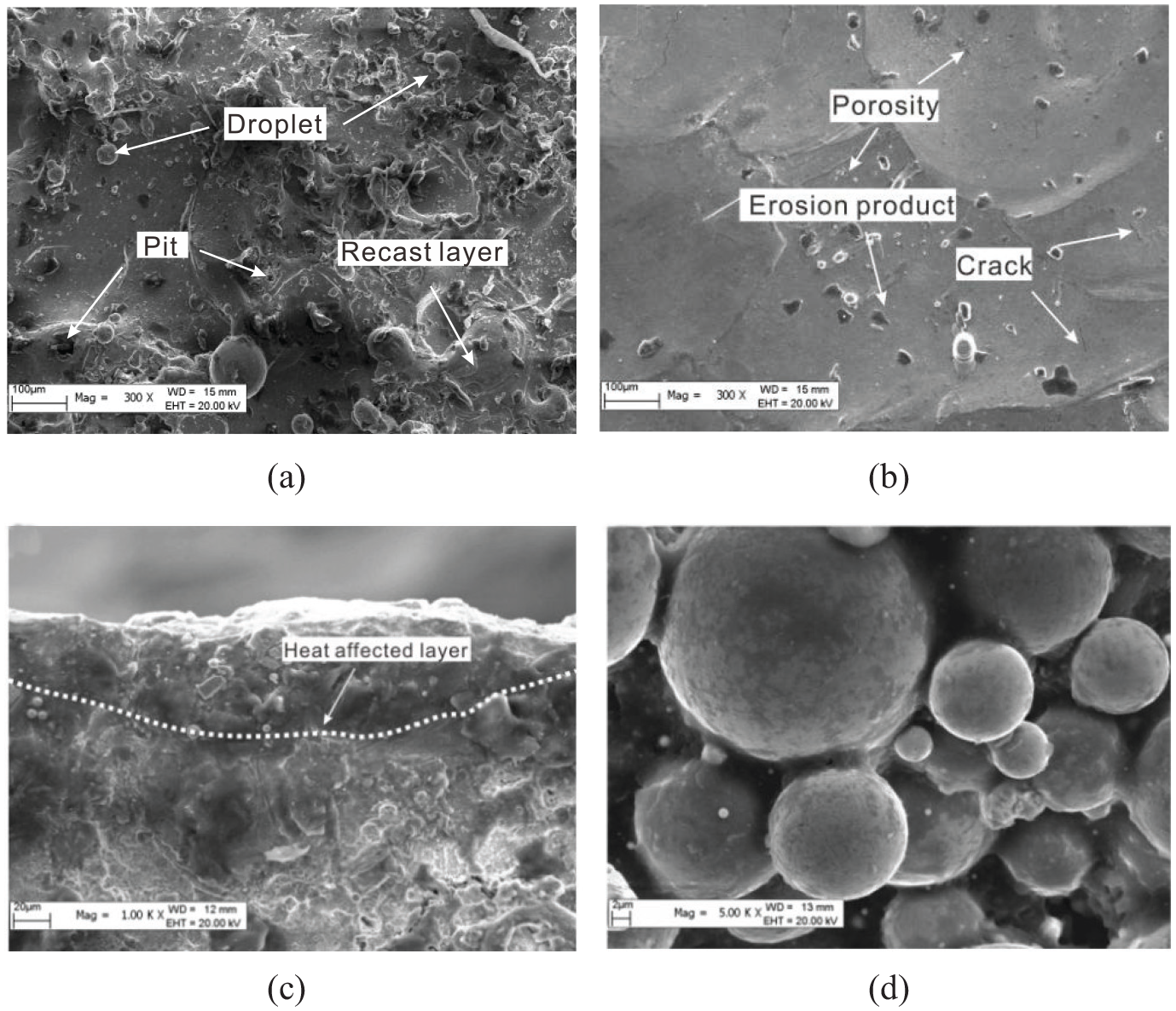
The micromorphology (a) droplets, pits, and recast layer, (b) porosity, cracks, and the electric erosion products, (c) heat affected layer, and (d) the etched particles.
Compared with EDM, SEAM adopts a large peak current to obtain greater energy density of arc plasma and employs a larger pulse width to enable arc plasma to fully develop and expand. Thus, SEAM is highly ionized to obtain higher heat and a stronger ability to melt and vaporize metal material, resulting in a geometrically increasing number of etched particles. Furthermore, the arc plasma expansion migrates under strong erosion of the medium, causing material in the melt zone to be detonated and thrown out, while promoting the generation and removal of etched particles.
Microstructure of the processed GH4169
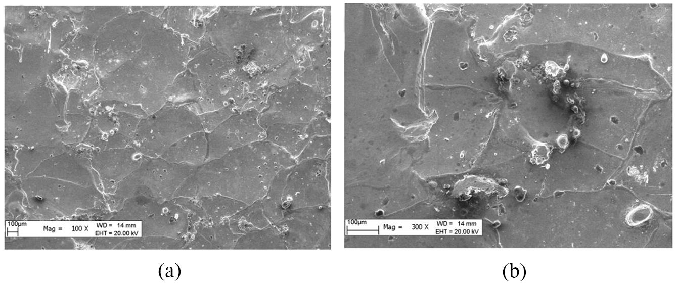
Some of the thermal energy released by the SEA continues to propagate on the workpiece electrode, evoking changes in the metallographic structure of the material and different structures of the matrix material. Under a large peak current condition, it is particularly important to form a carbon black film on the workpiece surface. In Figure 13, as the peak current increases, the equiaxed crystal of GH4169 no longer has a uniform distribution after heat erosion of the SEA and is mainly composed of coarse dendritic grains. Precipitates are separated at the grain boundaries, the grains grow noticeably, and many twins form in the structure. A large number of carbides are also distributed in the matrix, which reduce the deformation resistance and improve the plasticity of the alloy. In addition, the electroplastic effect increases with a rise in peak current, which can promote the dislocation slip of precipitated phase and enhance thermal erosion of the arc.
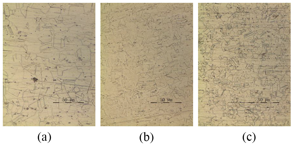
Microstructure of the processed GH4169: (a) 100×, (b) 300×, and (c) 500×.
Microtopography of the tool end face
The end faces of the tool at different magnifications were observed by SEM, as shown in Figure 14. The recast layer and debris particles were attached to the electrode surface and EDS was used to detect the elemental composition on the end face of the tool. The measurement area is illustrated in the blue rectangle in Figure 15. The EDS results illustrate that numerous elements belonging to GH4169 are found on recast layer and debris, such as Ni, Fe, Mo, and Cr, whereas the contents of W and Cu in tool electrodes decrease significantly (3.2% and 5.7%, respectively). This confirms that the recast layer and small debris particles attached to the tool electrode end surface are mainly composed of GH4169. Thus, the tool end face is covered with a layer of nickel-based alloy after processing. The layer is mainly derived from the sputtering of anode molten material under the force generated by arc discharge and the flushing liquid, which subjects the molten pool to a strong impact that causes splashing. Finally, under the cooling effect of the workpiece medium, the electrode surface is deposited and recoated to form a protective layer which protects the tool electrode from further erosion.
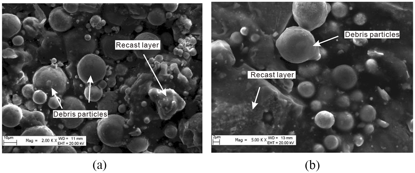
Tool end face: (a) 2000× and (b) 5000×.
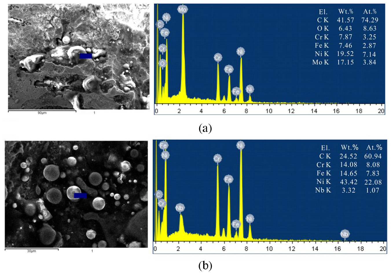
EDS analysis: (a) the recast layer and (b) the debris particles.
Conclusion
Arc movement characteristics and arc action rules in SEA milling were studied in this work, and an experiment was carried out to evaluate the erosion mechanism of GH4169 in SEA milling. The results are summarized as follows:
The discharge point was mainly concentrated between 20 and 22 V, and the average current was 200–500 A. In normal polarity processing, the arc discharge was relatively stable without the arc-cut phenomenon, and a single discharge within one pulse width was completed. The gap voltage decreased and fluctuated within the range of 15–20 V, and the peak current reached 600 A.
The single pulse arc discharge time was mainly between 5 and 20 μs. The arc plasma exhibited characteristics of concentrated energy density, high temperature, and a high MRR. The two parameters of arc discharge were discharge gap and discharge time, with values of 0.053 mm and 2180 μs, respectively. The workpiece surface was superposed by an infinite number of irregular electric etched pits, surface peaks became more regular, and vertices were either spherical or ellipsoidal. As arc energy increased, the size and shape characteristics of the peaks changed more clearly. The maximum MRR was 40 g/min and the minimum TWR was below 1%.
The SEAM adopted a large peak current and a larger pulse width which could produce defects on the workpiece surface such as droplets, pits, porosity, cracks, recast layers, and electric erosion products. Most etched particles were spherical. The particle size and distribution could reduce the breakdown force of the arc discharge, which affected the discharge position and the machining gap, resulting in a substantial change in discharge state.
After heat erosion of the SEA, the equiaxed crystal of GH4169 no longer had a uniform distribution and was mainly composed of coarse dendritic grains. Precipitates separated at the grain boundaries, the grains grew noticeably, and many twins formed in the structure. The EDS results illustrated that numerous elements belonging to GH4169 appeared on the recast layer and debris, including Ni, Fe, Mo, and Cr. The contents of W and Cu in tool electrodes decreased significantly to 3.2% and 5.7%, respectively.
Footnotes
Declaration of conflicting interests
The author(s) declared no potential conflicts of interest with respect to the research, authorship, and/or publication of this article.
Funding
The author(s) disclosed receipt of the following financial support for the research, authorship, and/or publication of this article: This research was supported by the Natural Science Foundation of China (51765063), the Autonomous University Scientific Research Program Natural Science Project (XJEDU2020Y011), and the Open Research Fund of State Key Laboratory for Manufacturing Systems Engineering (Xi’an Jiaotong University, sklms2019009).