
Abstract
High-speed cutting technology has the characteristics of high material removal rate and excellent processing quality. To investigate the surface quality of high-speed cutting Ti6Al4V alloy, the orthogonal cutting experiment is the cutting device based on improved Split-Hopkinson pressure bar carried out with a cutting speed of about 7–16 m/s. Surface roughness, residual stress and three-dimensional surface topography are examined to characterize the surface quality. And the chip geometry parameters are measured to analyze the formation mechanism of surface topography. The result shows that cutting force and surface roughness increase rapidly with the increase in depth of cut. In the meantime, the periodic microwaves appeared on the machined surface, and their amplitudes increase with the increase in depth of cut. However, surface roughness, residual stress and microwave amplitude all decrease with the increase in cutting speed. Moreover, it is found that the evolution trend of chip thickness and surface roughness with cutting parameters is very similar. Therefore, it can be inferred that there is a strong relationship between surface topography and chip morphology.
Introduction
Compared with the traditional cutting technology, high-speed cutting (HSC) technology holds the characteristics of high material removal rates, low energy consumption and superior processing quality, which has been widely used in aerospace, automobile, biomedical and other industries.1,2 Titanium alloy Ti6Al4V is a typical material for machining aero-engine compressor blade due to its excellent properties such as high specific strength, thermal stability and corrosion-resistant performance. 3 However, titanium alloy Ti6Al4V is an extremely difficult-to-cutting material with low machining efficiency and poor machining surface quality, which directly affects its industrial application. Therefore, it is of great significance to investigate the surface quality of titanium alloy Ti6Al4V under HSC conditions.
Conventional HSC experiments require HSC machine tools and the corresponding test instruments, which have the characteristics of high energy consumption, high cost and complicated operation. Split-Hopkinson pressure bar (SHPB) is an important experimental device for measuring the material’s mechanical properties at high strain rate condition. With the development of SHPB device, there are increased scholars who try to use the modified SHPB device for HSC experiment. Sutter et al. 4 first used the modified SHPB for HSC experiments at velocities ranging from 400 to 6000 m/min in 1997. Later, Sutter and colleagues5,6 used the HSC device based on modified SHPB to carry out HSC experiments of four metals: XC18 steel, Ti6Al4V, 42CrMo4 and C15. Meanwhile, the cutting temperature was measured, and analysis was based on an intensified charge-coupled device (CCD) camera. Subsequently, Ye et al. 7 built an HSC device based on light-gas gun which can realize the orthogonal cutting of AISI 1045 steel at a cutting speed of 30–200 m/s. The results show that the saw-tooth chip produced in HSC is due to periodic thermoplastic shear-banding. Lardi et al. 8 compared the chip formation process of HSC of 6060 aluminum alloy, 2024 aluminum alloy and 35 NCD16 steel, and found that the chip of 2024 aluminum alloy and 35 NCD16 steel turns from continuous ribbon to serrated segments. In short, there are many experiments conducted using the cutting device based on an improved SHPB system, but their research focus is limited to cutting force, cutting temperature and chip morphology.
The surface quality of titanium alloy components has a great influence on their performance in extreme service conditions. Therefore, many recent research works have been performed on the machined quality of titanium alloys. Ginting and Nouari 9 studied the influence of tool coating on surface quality with a cutting speed of 100–125 m/min. It was found that a better surface roughness value could be obtained by employing chemical vapor deposition (CVD)-coated carbide tool compared with the uncoated tool. Shokrani et al. 10 investigated the surface quality in end milling of titanium alloy Ti6Al4V with a cutting speed of 30–200 m/min at three different cooling conditions (dry, flood and cryogenic cooling); it was found that cryogenic cooling can significantly improve the surface quality. Yang and Liu 11 studied the effect of machining parameters on surface topography in peripheral milling Ti6Al4V alloy and found that a combination of optimal parameters—110 m/min of cutting speed, 0.2 mm/z of feed and 0.5 mm of depth of cut—can process low surface roughness. Longhui et al. 12 used a combination of finite element analysis and X-ray diffraction (XRD) to investigate the influence of cutting parameters and annealing on residual stress.
It is concluded from the analysis above that many scholars have studied the surface quality of titanium alloys, but most of the previous research works do not consider the surface quality of titanium alloys under HSC conditions. In this article, the high-speed orthogonal cutting experiment of Ti6Al4V alloy was carried out based on the improved SHPB cutting device. The effect of machining parameters on surface roughness, residual stress and three-dimensional (3D) surface topography was analyzed. In addition, the chip geometry parameters were measured to study the formation mechanism of surface topography.
Experimental method and materials
Experimental setup
The HSC device based on the improved SHPB is presented in Figure 1. It is composed of three parts: SHPB system (Figure 1(a)), cutting device (Figure 1(b)) and data acquisition system (Figure 1(c)).
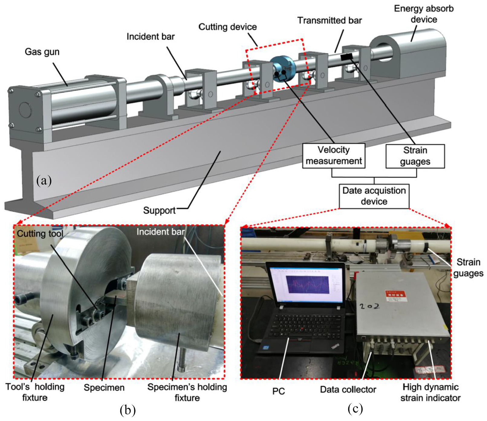
Schematic diagram of high-speed cutting device based on the SHPB system: (a) SHPB system, (b) cutting device and (c) data acquisition system.
The experimental principle of HSC based on the SHPB system is presented in Figure 2. Two cutting tools are symmetrically fixed on the tool’s holding fixture, while the specimen is fixed on the specimen’s holding fixture. According to the principle of SHPB device, the impact bar is shot by gas gun and then it impacts the incident bar. In the meantime, stress wave is produced in the incident bar, which drives the specimen to move forward. At last, the high-speed orthogonal cutting occurs when the specimen passes through the cutting tool rapidly. The cutting speed is adjusted by gas gun pressure, while the depth of cut is controlled by the specimen. The cutting speed and cutting force signals are collected by grating velocimeter and foil strain gauge, and then processed by date collector and strain indicator, respectively.
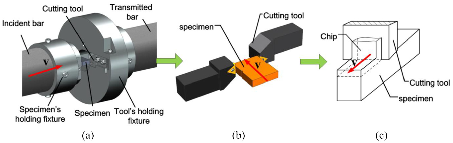
Experimental principle of HSC based on the SHPB system: (a) cutting experiment device, (b) simplified cutting model and (c) orthogonal cutting model.
Materials
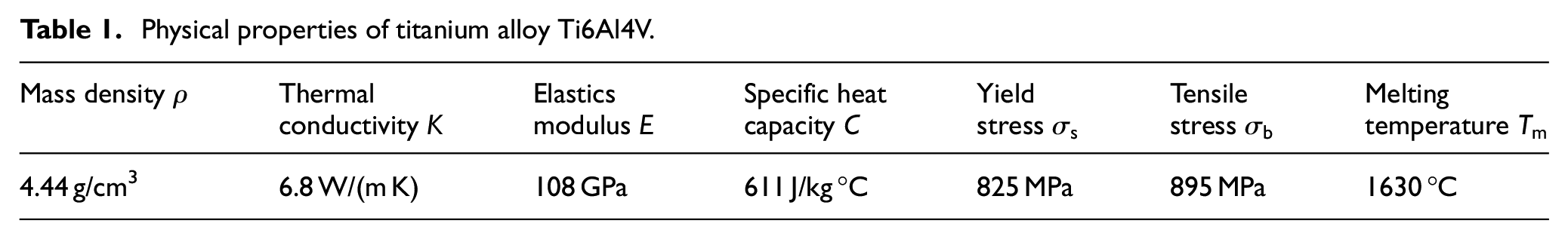
The material used in this experiment is Ti6Al4V, which is a medium strength two-phase alloy containing 6% Al and 4% V. Its physical properties are given in Table 1. The cemented carbide tool holder and the YBG202-coated cemented carbide insert were used in this article. The rake angle of the tool is 0° and the rear angle is 7°. The cutting specimen was designed based on the principle of HSC device. The shape of the specimen is a cuboid with a length × weight × height of about 40 × 35 × 10 mm3, as shown in Figure 3(a). The front-end guiding slot is used to guide the cutting process, the back end of the specimen is fixed in the specimen’s holding fixture, while the middle protruded material is an uncut layer used for cutting experiments (Figure 3(b)). The machined precision of specimen was ensured using the low-speed wire electrical discharge machining (WEDM) to ensure the uncut layer precision is below 0.01 mm.
Physical properties of titanium alloy Ti6Al4V.
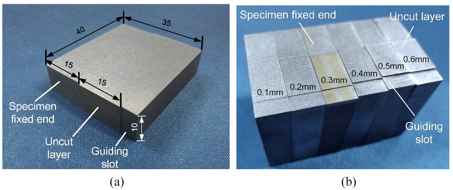
(a) Specimen size and (b) specimen with an uncut layer of different thicknesses.
Experimental design
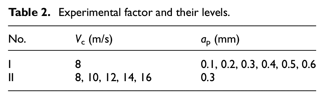
In this experiment, two factors including cutting speed Vc and depth of cut ap are considered in the HSC experiment, and their levels are listed in Table 2. The cutting speed is controlled by gas gun pressure, and the scanning speed of about 7–16 m/s can be obtained using the gas pressure of about 0.03–0.08 MPa. The depth of cut is controlled by the uncut layer height of specimen, as shown in Figure 3(b). The relative position of the specimen and cutting tool is adjusted before the cutting experiment. Meanwhile, a pair of new inserts are replaced to reduce the experimental error resulting from tool wear.
Experimental factor and their levels.
After the cutting test, surface roughness, 3D surface topography and surface residual stress are examined to characterize the machined surface quality, and the chip morphology and geometry parameters are measured to analyze the formation mechanism of surface topography. The surface roughness and 3D surface topography were measured using a surface topography analyzer (Mahr XT20). The contour arithmetic mean deviation, Ra, was used to characterize surface roughness. For each machined surface, measurement of surface roughness (along the cutting direction as shown in Figure 4) was repeated three times and the mean value of six times was adopted as the final result. In this experiment, the surface residual stress was examined by an XRD method by the measuring equipment Proto-LXRD MG2000. The measured position is in the middle of the uncut layer (red point in Figure 4), and the residual stress parallel to the cutting direction is defined as σc and that parallel to the cutting width direction is defined as σw, as shown in Figure 4. In addition, the chips were collected, polished and then observed using an optical microscope (OM).
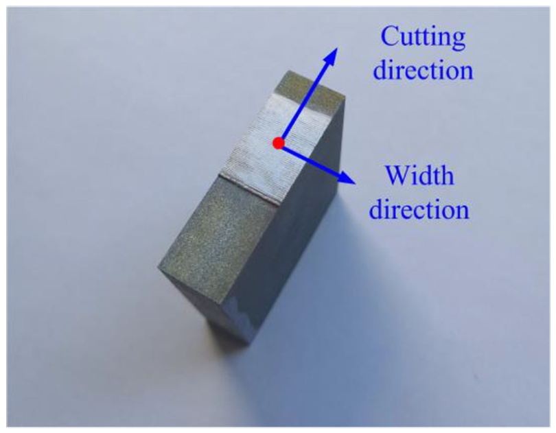
Measurement position and direction of surface roughness and residual stress.
Results and discussion
The surface quality has significant influence on service performance of titanium alloy components. This study, thus, examined and analyzed the surface quality with such evaluating indicators as roughness, residual stress and 3D surface topography. Due to the experimental error, there exists a certain deviation between the measured value and design value of cutting sped. In this article, the measured value was taken as final results. The measurement results are presented in Table 3.
Results of cutting experiment and surface quality measurement.
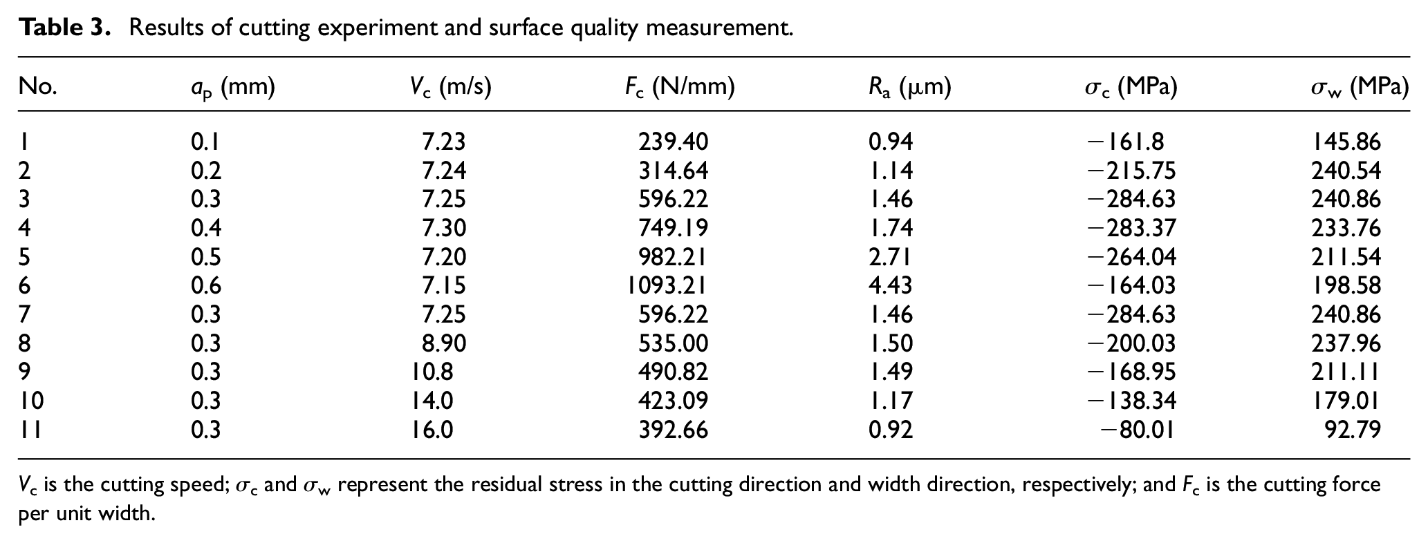
V c is the cutting speed; σc and σw represent the residual stress in the cutting direction and width direction, respectively; and Fc is the cutting force per unit width.
Cutting force
The cutting force directly affects the energy consumption, machining deformation and machining surface quality of material cutting process. Therefore, this study investigated the cutting force at different cutting parameters to analyze its influence on machined surface quality. The variation of the cutting force Fc (divided by cutting width b, exerted on a single cutting tool) with the depth of cut and cutting speed is presented in Figure 5.
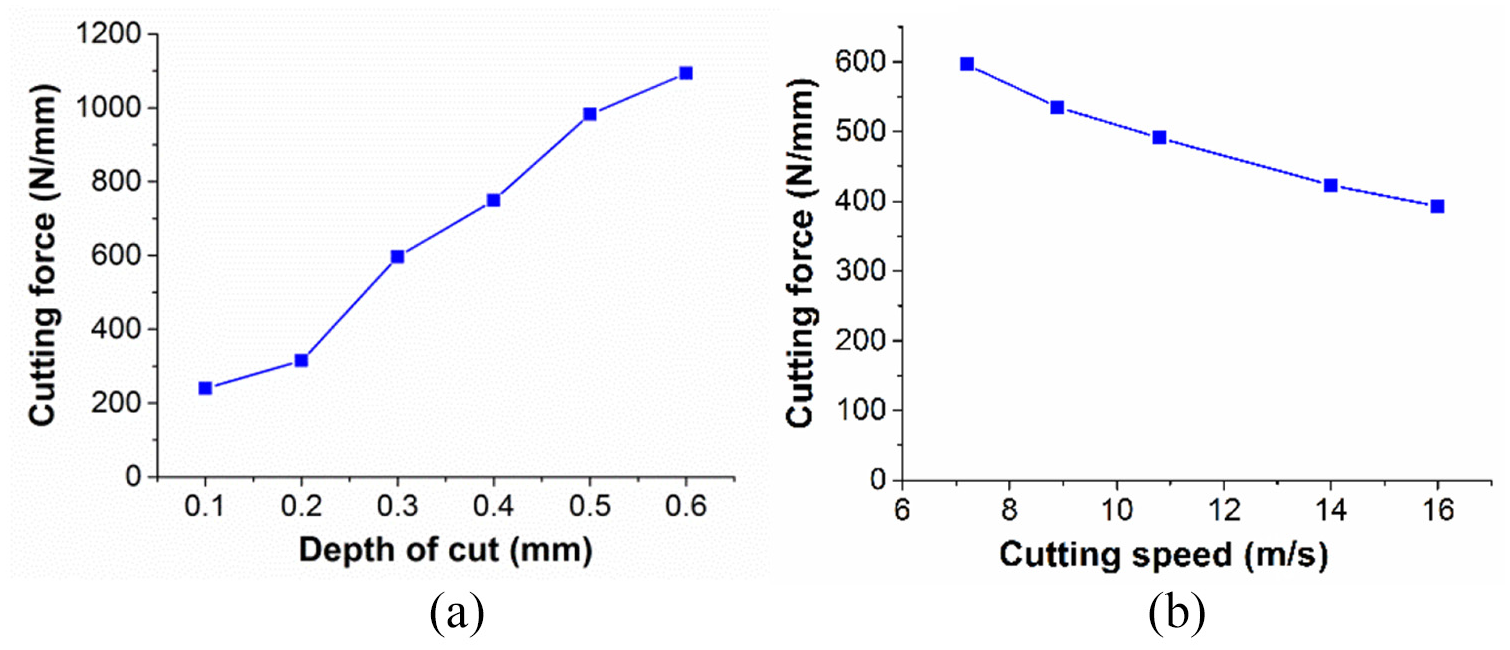
Cutting force (Fc) in the variation of: (a) depth of cut ap, (Vc = ~7.25 m/s) and (b) cutting speed Vc, (ap = 0.3 mm).
It can be seen from Figure 5(a) that the depth of cut has a great influence on the cutting force, and the cutting force increases linearly with the increase in depth of cut. This is due to fact that the depth of cut directly affects the material’s shear deformation. According to the orthogonal cutting principle (two-dimensional orthogonal cutting model as shown in Figure 6), the tangential cutting force Fc can be calculated by

where Ftotal is the total cutting force; τ is the shear stress; h is the depth of cut (same as ap in this experiment); b is the cutting width; and α, β, γ and φ represent the rake angle of the tool, the clearance angle, the shear angle and the friction angle, respectively. According to equation (1), the cutting force increased linearly with the increase in depth of cut at the constant cutting width, which is consistent with the experimental results.
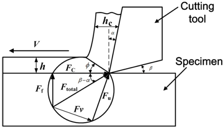
Two-dimensional orthogonal cutting model.
It can be seen from Figure 5(b) that the cutting force Fc decreases from about 600 to 400 N with the increase in cutting speed. This can be attributed to the heat softening effect caused by the increase in material removal rate. The material removal rate Qc is defined as material removal volume per unit time, which can be calculated as follows

where Vc is the cutting speed. For II tests, the depth of cut h and cutting width b are constant at 0.3 and 10 mm, respectively, while the cutting speed is increased from 7.25 to 16 m/s. Therefore, it can be inferred that the material removal rate increases with the increase in cutting speed, which causes the cutting temperature to rise, and a thin micro-melting layer is formed on the tool–chip surface, leading to a reduction in friction coefficient between the tool and chip surface and a drop in the cutting force. In addition, the decrease in shear stress τ results from the material softening effect, which further causes the cutting force to decrease.13,14
Surface residual stress
The residual stress results from material plastic deformation caused by mechanical stress and thermal stress during the cutting process. In general, the mechanical stress will produce compressive plastic deformation and compressive residual stress on the machined surface. However, the heat stress produces tensile plastic deformation on the machined surface. The surface residual stress is the comprehensive effect caused by mechanical stress and thermal stress. Compressive stress may be seen if the mechanical stress plays a leading role in the cutting zone, otherwise the residual stress will be tensile stress. Figure 7 presents the residual stress in variation of the depth of cut (a) and cutting speed (b). It can be found that the residual stresses in the cutting direction (blue line) are all compressive stress, while the residual stresses in the cutting width direction (red line) are all tensile stress.
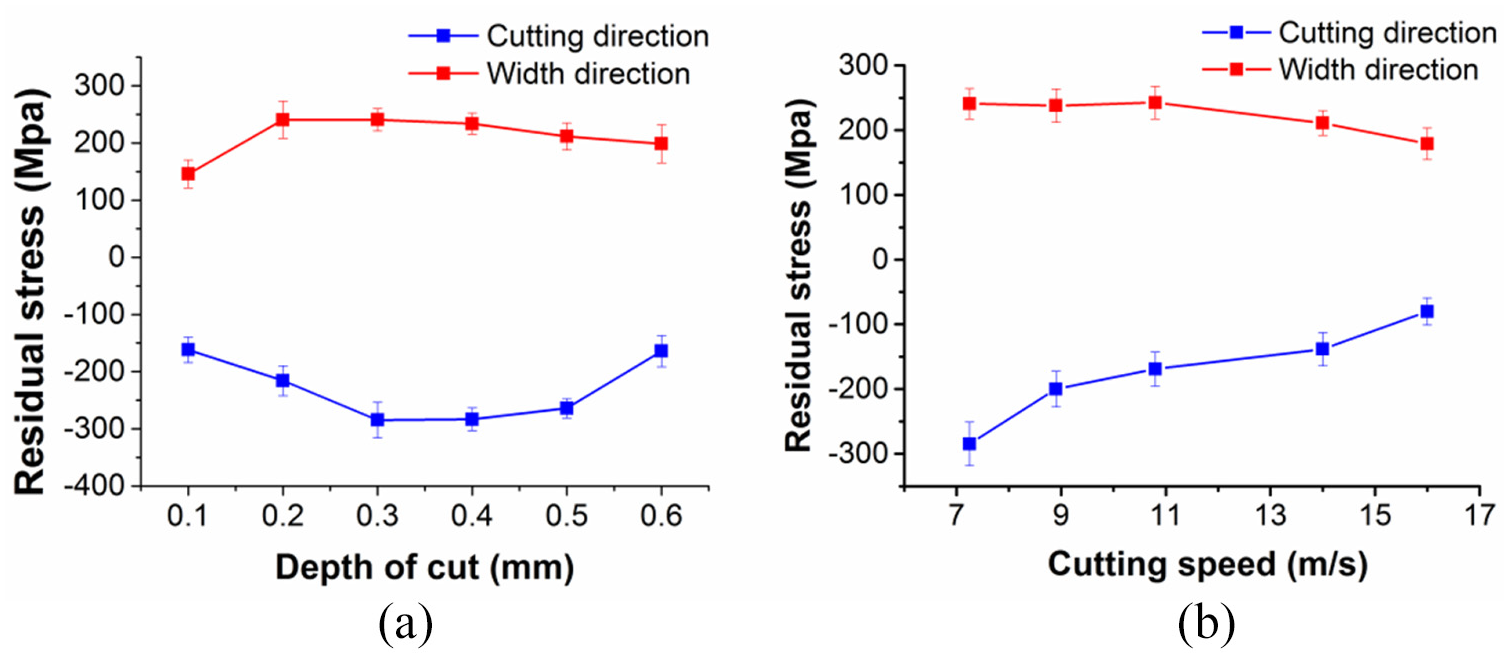
Residual stress (σ) in variation of: (a) depth of cut ap, (Vc = ~7.25 m/s) and (b) cutting speed Vc, (ap = 0.3 mm).
It can be seen from Figure 7(a) that the compressive residual stress in cutting direction increases first and then decreases. The increase in compressive residual stress is due to the increase in mechanical stress resulting from the significant increase in cutting force with the depth of cut (as shown in Figure 5(a)). However, as the depth of cut further increases (above 0.3 mm), the material removal rate increases sharply, which causes the increase in cutting temperature. Therefore, the compressive residual stress by mechanical stress and the tensile residual stress by thermal stress offset each other, resulting in a decrease in compressive residual stress.
The residual stresses in the cutting direction decrease with the increase in cutting speed (Figure 7(b)). This is due to the fact that as the cutting speed increases, the cutting force decreases (as shown in Figure 5(b)), resulting in a decrease in mechanical stress. In the meantime, the cutting heat generated by plastic deformation is increased due to the increased material removal rate, which causes an increase in tensile residual stress. Therefore, both the mechanical strain and the thermal strain lead to the decrease in compressive residual stress.
The residual stresses in the width direction are all tensile stress. This is because the material in the width direction is not constrained, so the uncut layer materials will inevitably be plastic flowing along the width direction during HSC of specimens, resulting in tensile residual stress in the width direction.
Surface roughness and surface topography
The surface roughness and surface 3D topography vary with the cutting parameters, as shown in Figure 8. It can be seen from Figure 8(a) that the surface roughness increases rapidly from 0.94 to 4.43 μm as the depth of cut increases; meanwhile, the amplitude of surface periodic ripple increases significantly as the depth of cut increases. This is due to the fact that the uncut layer’s surface roughness and thickness increase with the increase in depth of cut, which causes the increase in intensified material’s plastic deformation and surface roughness. Furthermore, as the depth of cut increases, the cutting force fluctuation increases resulting from the increase in chip thickness (it will be discussed in section “Relationship between chip morphology and machined surface topography”), which further causes obvious periodic microwaves on the machined surface, leading to the increase in surface roughness.
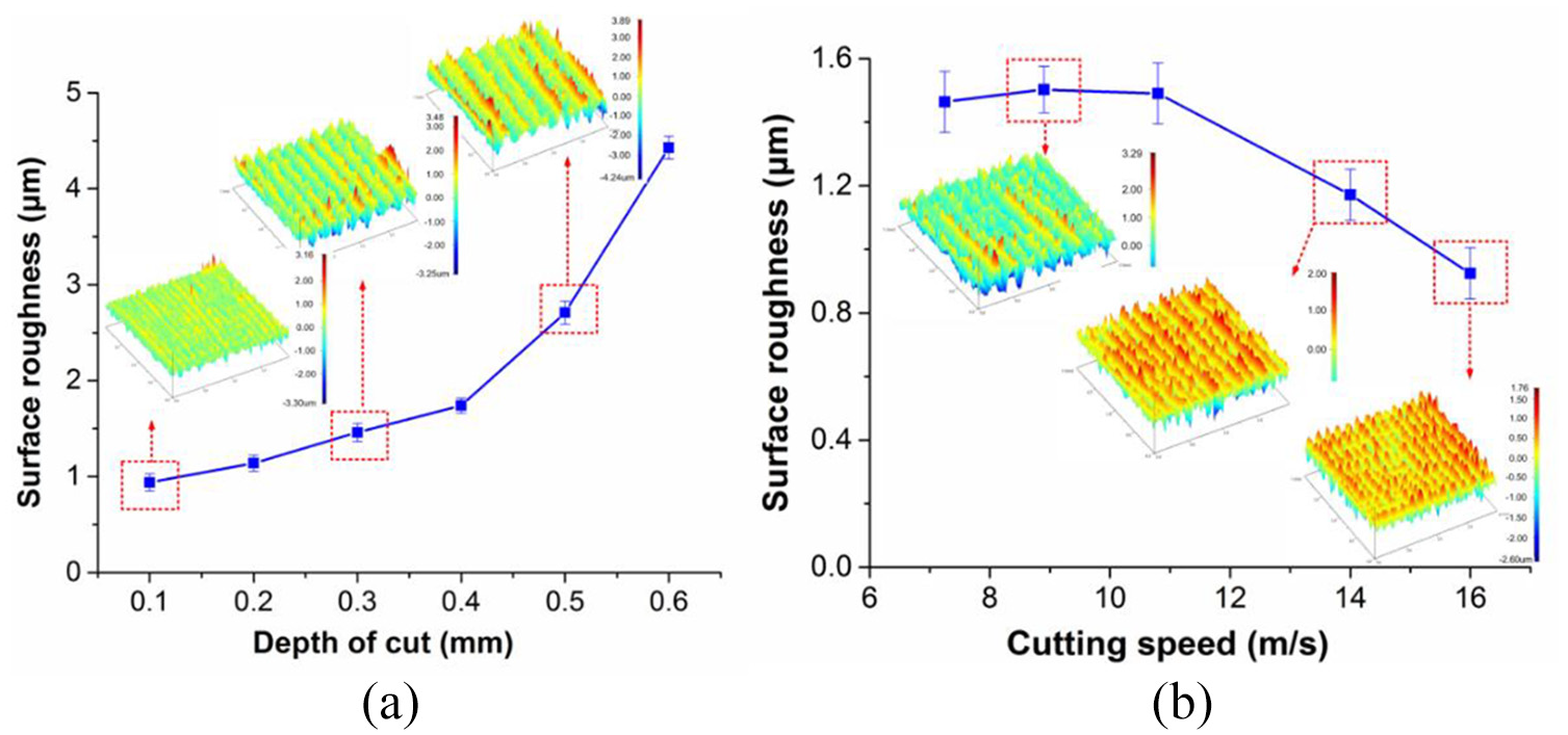
Surface roughness and topography in variation of: (a) depth of cut ap, (Vc = ~7.25 m/s) and (b) cutting speed Vc, (ap = 0.3 mm).
In contrast, the surface roughness remains steady when the cutting speed is from 7.25 to 10.8 m/s. However, with further increase in cutting speed (over 10.8 m/s), the surface roughness decreases steadily from 1.53 to 0.97 μm. When the cutting speed is 7.25–10.8 m/s, the cutting force is relatively larger as shown in Figure 5(b), which causes large material plastic deformation and high surface roughness on the machined surface. However, the thermal softening effect is intensified with further increase in cutting speed, which leads to the decrease in cutting force and surface roughness. 15 In addition, it will be proved in section “Relationship between chip morphology and machined surface topography” that the cutting force fluctuation decreases with the increase in cutting speed, which will cause an increase in the amplitude of surface periodic ripple and a decrease in surface roughness.
Chip morphology and geometric parameters
The chip morphology at different cutting parameters is presented in Figure 9, and the corresponding machining parameters are consistent with 3D topography in Figure 8. It can be observed that the chips in Figure 9 are all saw-tooth chips. This can be attributed to the material properties such as high specific heat and poor thermal conductivity, as shown in Table 1.
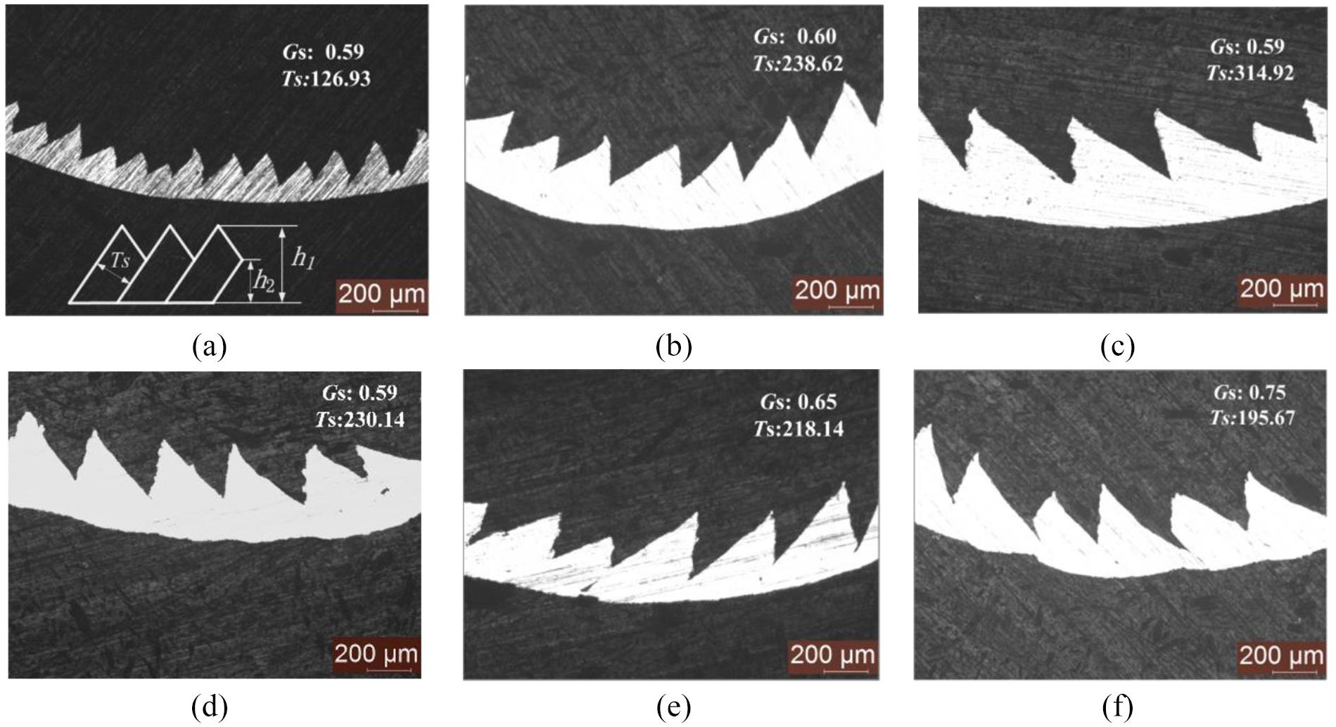
Chip morphology under different cutting parameters: (a) Vc = 7.23 m/s and ap = 0.1 mm, (b) Vc = 7.25 m/s and ap = 0.3 mm, (c) Vc = 7.20 m/s and ap = 0.5 mm, (d) Vc = 8.9 m/s and ap = 0.3 mm, (e) Vc = 14.0 m/s and ap = 0.3 mm, and (f) Vc = 16.0 m/s and ap = 0.3 mm.
Due to high cutting speed and high specific strength, a large amount of cutting heat is generated at the cutting zone during HSC of Ti6A14V, which will be accumulated in the shear zone, leading to the material softening effect and a drop in shear stress. Therefore, once the load stress exceeds the required shear stress of shear zone material, the saw-tooth chips will be formed, which is called an adiabatic shear effect. 16
Therefore, when the cutting speed is lower, the cutting heat produced in the cutting zone is relatively less. Meanwhile, the cutting heat can be taken away by the cutting tool and chips in time. So the collected chip by low cutting speed is a continuous ribbon chip. However, with the increase in cutting speed, the saw-tooth chips will be generated once the cutting speed exceeds the critical cutting speed (CCS). Owing to the high specific heat and low thermal conductivity of Ti6Al4V, the CCS of Ti6Al4V alloy is relatively low, which is below 30 m/min measured by Zhen-Bin and Komanduri. 17 In these tests, the lowest cutting speed measured is 7.15 m/s, which is much higher than the CCS of saw-tooth chips. This is the reason why the chips in this experiment are all saw-tooth chips.
In this experiment, the chip geometry parameters, such as chip thickness Ts (the thickness of sawed segment) and segmentation degree Gs were measured, and the result is presented in Figure 10. The segmentation degree (Gs) is defined as

where h1 and h2 are the root height and tooth top of saw-tooth chip, respectively, as shown in Figure 9(a). It can be observed that the chip thickness Ts increases significantly from about 126.93 to 314.96 μm as the depth of cut increases, while the segmentation degree Gs is constant at about 0.59. The increase in chip thickness Ts can be attributed to the increase in uncut layer thickness, which causes the increase in chip size and chip thickness Ts generally. However, the chip thickness is decreased from 238.62 to 195.67 μm with the increase in cutting speed, while the segmentation degree Gs increases from 0.59 to 0.70. This is due to the fact that the thermal softening effect is intensified, which causes the increase in material deformation and chip segmentation degree Gs. However, the shear angle also increases with the increase in cutting speed, which leads to the decrease in chip thickness Ts. 15
Relationship between chip morphology and machined surface topography
To further investigate the relationship between chip morphology and surface topography, the evolution of chip thickness and roughness with cutting speed and depth of cut is analyzed, and the result is shown in Figure 10. It can be seen that the surface roughness and chip thickness all increase with the increase in depth of cut and decrease with the increase in cutting speed. The evolution trend between chip thickness and surface roughness with the cutting parameters is very similar (except for the HSC stage). Therefore, it can be inferred that the chip thickness is one of the key factors which affects the machined surface topography.
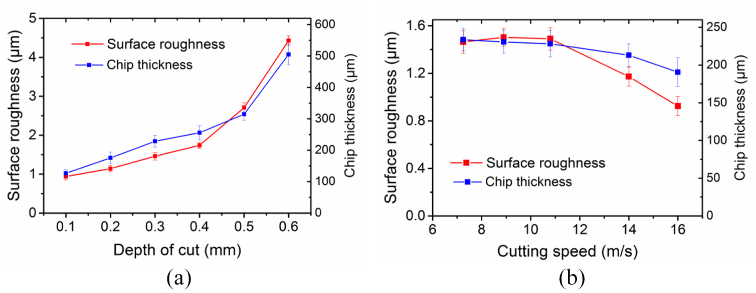
Evolution of surface roughness and chip thickness with cutting parameters: (a) depth of cut ap, (Vc = ~7.25 m/s) and (b) cutting speed Vc, (ap = 0.3 mm).
As mentioned in section “Chip morphology and geometric parameters,” the saw-tooth chips were caused by material’s adiabatic shear effect. It has been proved by Sun et al. 18 and Zhang et al. 19 that the adiabatic shear effect will cause the cutting force fluctuation during HSC of titanium alloy. In addition, the possible phase transformation in the shear deformation zone will exacerbate cutting force fluctuations. Therefore, it can be inferred that saw-tooth chips resulting from the adiabatic shear effect and phase transformation cause the cutting force fluctuation, which further causes periodic peaks and valleys on the machined surface.
It can be observed from Figure 10(a) that the surface roughness increases as the depth of cut increases. One of the reasons is that the chip thickness is significantly increased, which causes the increase in cutting force fluctuation, further leading to the increase in the amplitude of the periodic microwave and surface roughness. Meanwhile, it can be observed from Figure 10(b) that the surface roughness decreases with the increase in cutting speed. The decrease in surface roughness can also be attributed to the decrease in cutting force fluctuation resulting from the decrease in chip thickness. As we know, the machined surface morphology is affected by many factors. In the HSC stage, the decrease in cutting force leads to the reduction in cutting system vibration. This may be the reason that the downtrend of surface roughness is slightly lower than the chip thickness.
Conclusion
In this article, the HSC experiment on titanium alloy Ti6Al4V was executed based on the improved SHPB cutting device. The influence of cutting speed and depth of cut on surface roughness, residual stress and surface topography was investigated. In the meantime, the cutting force and chip morphology were collected and measured to analyze the formation mechanism of the machined surface. The conclusions can be summarized as follows:
The cutting force increases linearly as the depth of cut increases, which can be attributed to the increase in material shear deformation. However, owing to the thermal softening effect, the cutting force decreases steadily with the increase in cutting speed.
The surface residual stress along the cutting direction was compressive stress, while along the width direction it was tensile stress. Moreover, with the increase in cutting speed, the residual stress in both cutting direction and width direction decreases.
Among the two factors, the depth of cut has the significant influence on surface roughness and topography, and the greater depth of cut, the greater surface roughness and microwave amplitude, while the surface roughness and surface microwave amplitude decrease gradually with the increase in cutting speed.
The evolution trend between chip thickness of sawed segment and surface roughness with the cutting parameter was very similar. It could be inferred that the cutting force fluctuation resulting from saw-tooth chips is one of the important reasons that causes periodic surface topography.
Overall, the parameter combination of small depth of cut and large cutting speed is recommended for processing superior surface quality during HSC of Ti6Al4V alloy.
Footnotes
Acknowledgements
The authors would like to thank Prof. Weiguo Guo and Dr Longyang Chen from School of Aeronautics, Northwestern Polytechnical University for their help in high-speed cutting experiments.
Declaration of conflicting interests
The author(s) declared no potential conflicts of interest with respect to the research, authorship, and/or publication of this article.
Funding
The author(s) disclosed receipt of the following financial support for the research, authorship, and/or publication of this article: This study was supported by NSAF (Grant No. U1830122) and the National Natural Science Foundation of China (Grant No. 51775443).