
Abstract
In the forming process of long threads by axial self-infeed rolling process, the protrusion generates on the top of the tooth profile, which affects the strength and precision of the formed threads. In this article, the principle of the axial self-infeed rolling process was described, and the finite element model was established to simulate the forming process of threads. The formation mechanism of protrusion was analyzed through material flow, which was verified by experiments. The pre-rolling angle and material’s influence on the protrusion size was also investigated. The results showed that the axial motion of the rollers squeezed one flank of the tooth, leading to higher protrusion on the face side as compared to the other side. During the rolling process, the height of the protrusion increased first and then decreased, reaching the maximum value when the height of the formed tooth was 73% of the whole tooth. In order to reduce the protrusion height, the pre-rolling angle should be 2°.
Keywords
Introduction
The rolling operation is widely used in the manufacture of threads as it can improve the performance of threads and save materials.1–5 The axial infeed rolling process is applied to form long threads such as lead screw, which can reduce the requirements on the forming equipment. 6
Generally, limited by the high pressure and the die life, the addendum of formed threads has no contact with the dedendum of the roller during the rolling process. On the top of tooth profile, the formed protrusion reduces the strength and lifetime of the formed threads. In addition, the protrusion size influences the forming precision.
The protrusion is not just for the axial self-infeed rolling process. It also exists in the tapping7–10 and rolling thread by the radial infeed rolling process. 11 There are some scholars who have carried out studies on the formation of the protrusion
For the tapping, the protrusion leads to split crest. Warrington et al.12,13 developed a finite element model and conducted linear scratch experiments to analyze the influence of the tooth number, rigid size, and attack angle on protrusion formation. Mathurin et al. 14 studied an assembly process with thread forming screw by the finite element model. The material flow and the most influential process parameters were analyzed. De Carvalho et al. 15 investigated the effects of the factors on torque, hardness, fill rate, and thrust force of the tapping process in cast magnesium alloy. And the best closure of the split crest was achieved. Fromentin et al. 16 studied the effect of different lubrications on the split crest in form tapping. Stéphan et al. 17 studied the internal thread forming processes with forming screws and analyzed the influence of the hole diameter on the split crest.
For the external thread forming, Song et al. 11 described the deformation process and displayed four kinds of the protrusions in the radial infeed rolling process. Nitu et al. 18 analyzed the wedge rolling process through experiments and simulation. Domblesky and Feng19,20 investigated the external thread formation of the radial infeed rolling process through the finite element model. Maciel et al. 21 compared the characteristics of the machined and formed external threads in titanium alloy, but the formation process of the external thread was rarely mentioned. Groche and Kramer22,23 studied the effects of frictional conditions and the defect under the single-thread profile rolling with flat die. The protrusion height under different frictional factors was also compared.
Currently, the studies about axial self-infeed rolling process are quite limited. Zhang et al. 24 analyzed the deformation characteristics of the tooth. They found that the distribution of the equivalent strain on both flanks was asymmetric. The performance of formed thread shaft was investigated. But the effects of protrusion formation during the axial self-infeed rolling process were rarely analyzed. Therefore, understanding the formation mechanism of protrusion and reducing the size of the protrusion are significant for improving the thread quality.
In this study, the finite element model of the axial self-infeed rolling process for long threads is established. The formation mechanism of protrusion is investigated through the force and flow analysis in detail, and it is verified by rolling experiments. The influence of the pre-rolling angle and material on the protrusion height is analyzed.
The principle of axial self-infeed rolling process
The quantity of the rollers is three, located evenly around the blank and the end faces of the rollers are aligned as shown in Figure 1(a). The structures of each roller are same which include three parts: the exit part, the correction part, and the pre-rolling part, as shown in Figure 1(b). The pre-rolling part has an angle of α1, which is used to pre-form the tooth profile. The correction part calibrates the tooth profile. And the exit part has an angle of α2, which is convenient for the return after the thread forming. In this study, the pre-rolling angle and the exit angle are 2°, respectively.
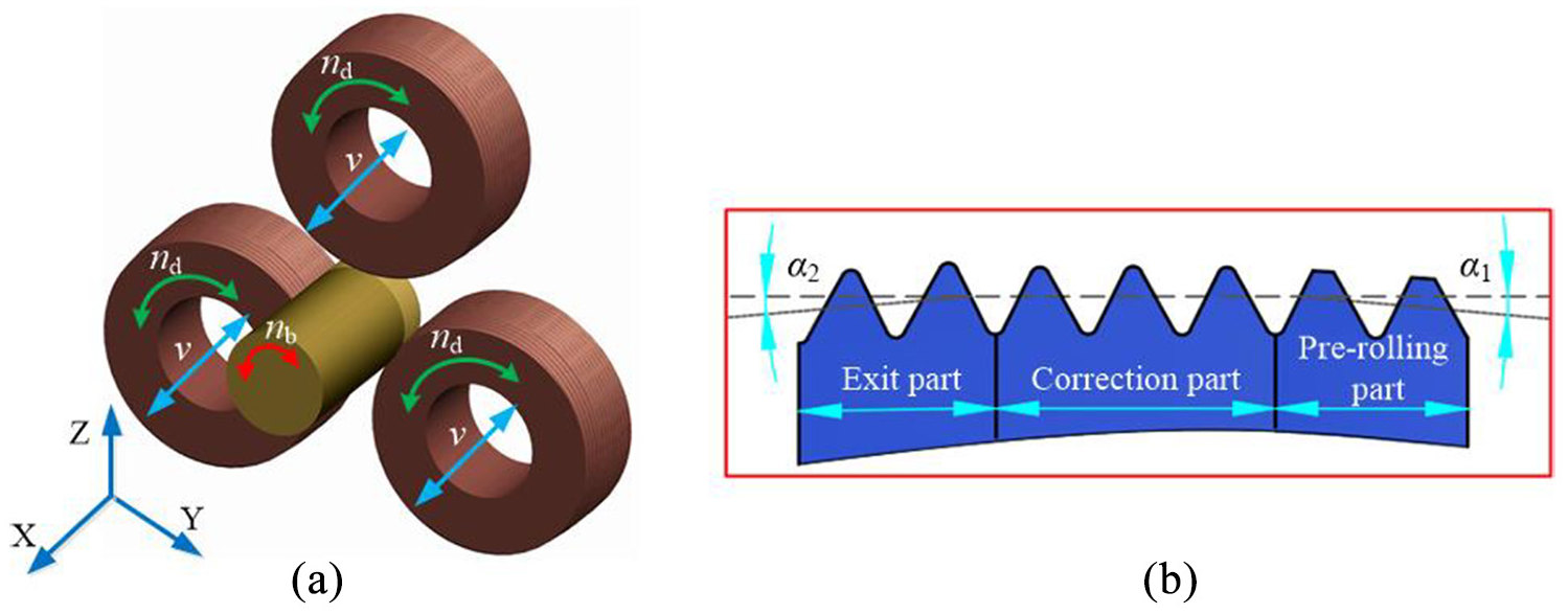
Diagram of the principle: (a) principle of the axial self-infeed rolling process and (b) roller structures.
The axial self-infeed rolling process includes two stages: the forming stage and the returning stage, as shown in Figure 1(a). In the forming stage, first, the blank rotates with the speed of nb and the direction is clockwise while the rollers are kept still. There is no contact between the blank and the rollers. Second, when the rollers contact with the blank, the rollers begin to rotate with the speed of nd and the direction is counterclockwise. Meanwhile, the rollers move along the x-direction with the speed of v, because the lead angles between the roller and the formed thread are different. The material flows into the tooth groove of the roller, and the tooth profile of the threads is gradually formed. After the deformation is completed, the rollers need to return. In the returning stage, the blank rotates with the speed of nb and the direction is counterclockwise. The rollers also rotate with the speed of nd and the direction is clockwise, and the rollers move along the opposite direction of the x. Finally, the rollers return to the initial position and the forming process is completed.
The finite element model of axial self-infeed rolling process
In this simulation, the Deform-3D software was used to analyze the forming process of the threads. The relative position between the blank and the rollers is shown in Figure 2(a). In order to save the simulation time, the model is simplified. The blank is shortened and a quarter of the blank is built. The symmetry planes and the constraint face are shown in Figure 2(b). The local refinement mesh was used to improve the simulation precision as shown in Figure 2(c).
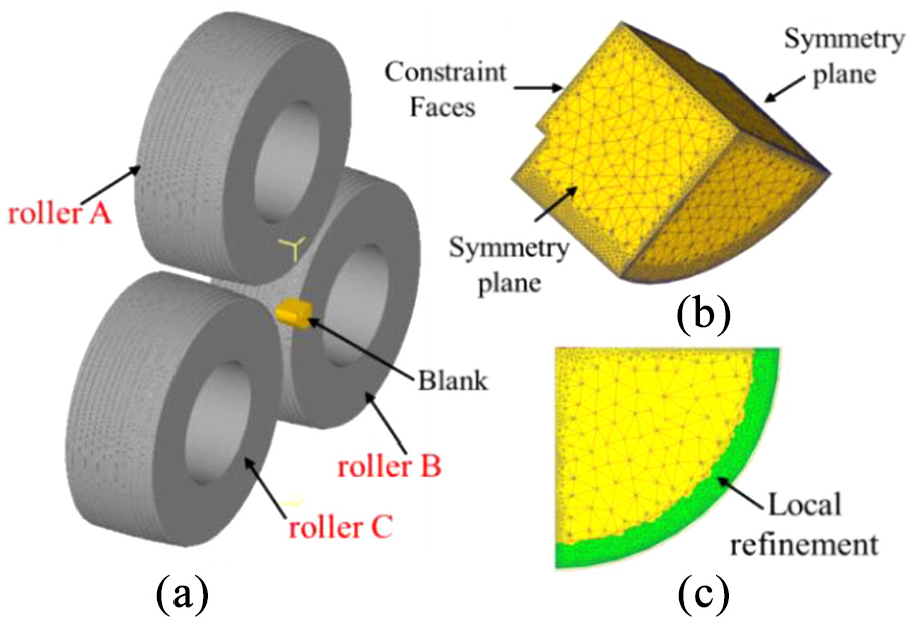
Finite element simulation model of axial self-infeed rolling process: (a) the relative position of the rollers and the blank, (b) constraint conditions, and (c) mesh refinement.
The mesh type was set as tetrahedral mesh, and the size ratio was 5. The remeshing criterion was global remeshing, the relative interference depth was 0.7, and the minimum size of the mesh was 0.06 mm. During the simulation, the time step was 0.05 s and the simulation step was 3000. The shear friction was applied and the friction factor was 0.21 25 since the contact surface between the roller and the blank was under high pressure. The elastic recovery and the Bauschinger effects were not taken into consideration. In the simulation, the rollers were regarded as rigid tools.
The material of the blank is the medium carbon steel AISI 1045 and copper, formed at room temperature and the temperature did not increase remarkably during the process. Therefore, the temperature influence can be ignored. The Johnson–Cook constitutive model was utilized, which is expressed in equation (1)
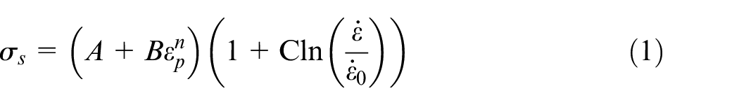
where σ
s
is the yield stress; A, B, C, and n are the material constants. The equivalent strain rate
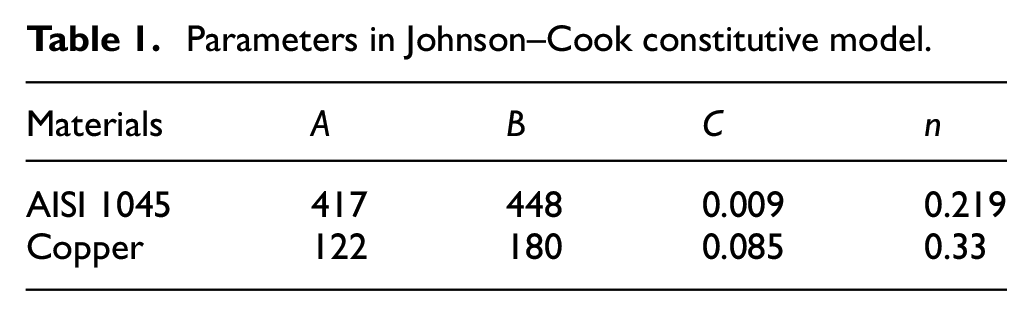
Parameters in Johnson–Cook constitutive model.
In practice, the blank rotates and the rollers rotate around their own axes. While in this simulation, the blank is fixed through constraint face, so in order to form the thread, the rollers not only rotate around their own axes but also rotate around the blank’s axis.
In the simulation, the diameter of the blank is 22.75 mm, which is fixed through the constraint face. The rollers rotate around their own centers with the speed of 10 r/min and around the blank’s axis with the speed of 2.07 r/min. The rollers move along the axial direction with the speed of 0.293 mm/s. The required major diameter and the pitch of the formed threads are 24 and 3 mm, respectively.
In order to reduce the effects of symmetry planes on the material flow, the material flow and the tooth profile are evaluated on the A–A plane which is located on the middle of the blank. The angle between A–A plane and symmetry planes is 45°, as shown in Figure 3.
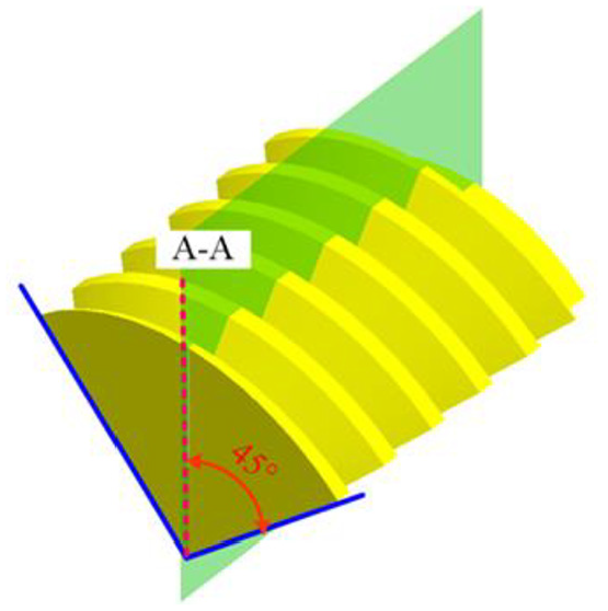
The analytical region A–A.
For the symmetry plane, the material cannot flow across it. Therefore, the symmetry plane mainly restricts the circumferential material flow in the forming process of threads. In the forming process of threads, the circumferential deformation is smaller 24 and the radial deformation is the main deformation. 26 In another aspect, the analytical plane A–A is located on the middle of the blank. The limitation of circumferential material flow on the plane A–A is smaller as compared to the symmetry plane. Therefore, the symmetry plane has a small effect on the middle of the blank.
Analysis of the formation mechanism of protrusion
Material flow analysis
Figure 4 shows the velocity vector diagram of the blank during the rolling process. First, the addendum of the roller squeezes the blank, and then the material slightly flows along the radial direction. But the resistance along the radial direction is huge. According to the law of minimum resistance, the nearby material moves to the tooth groove of the roller which leads to the tooth being wider and taller on the blank.
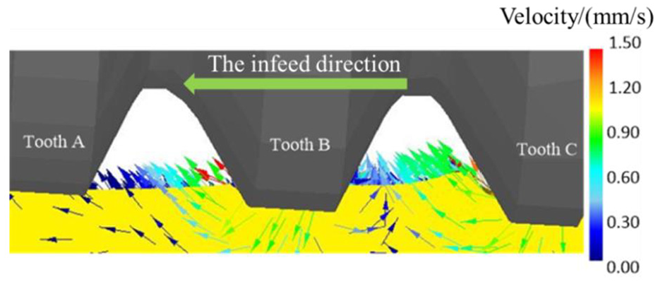
Velocity vector diagram of the blank.
In order to study the material flow characteristics, four points on the tooth profile are selected to analyze the velocity of the material flow. The positions of these four points on the tooth profile are shown in Figure 5(a). The velocity curves of these four points, shown in Figure 5(b), were obtained through the point tracking approach. The longitudinal axis is the actual velocity of material flow. When rollers contact with blank, the velocity of material flow increases to maximum value with the magnitude of VP4 > VP1 > VP3 > VP2. The velocities on both flanks are larger, and the velocity of point P4 is higher than that of the point P1.
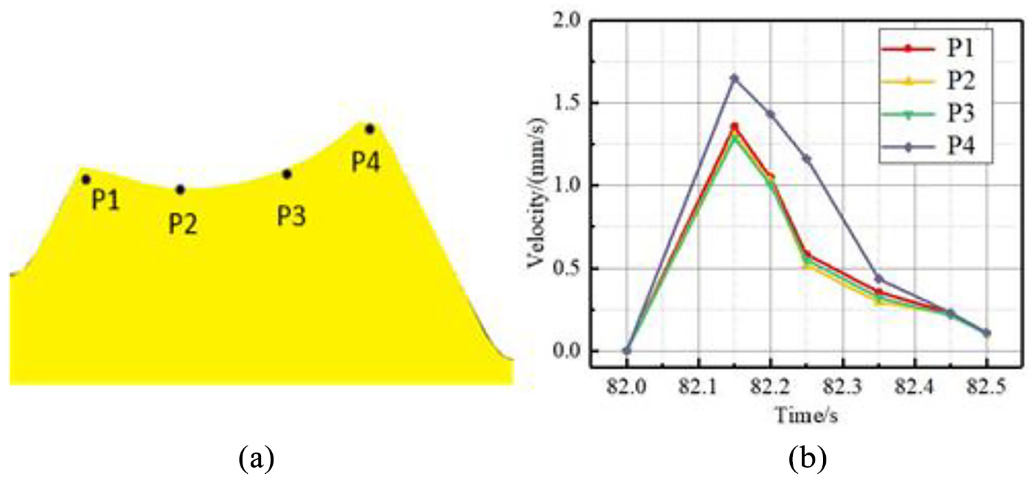
Velocity of the point tracking: (a) point position and (b) velocity curve.
Protrusion evaluation
As shown in Figure 6(a), the left side of the blank contacts with the right side of tooth A, facing the roller infeed direction and is named as “face side.” The right side of blank contacts with the left side of tooth B, against the roller infeed direction and is named as “back side.”
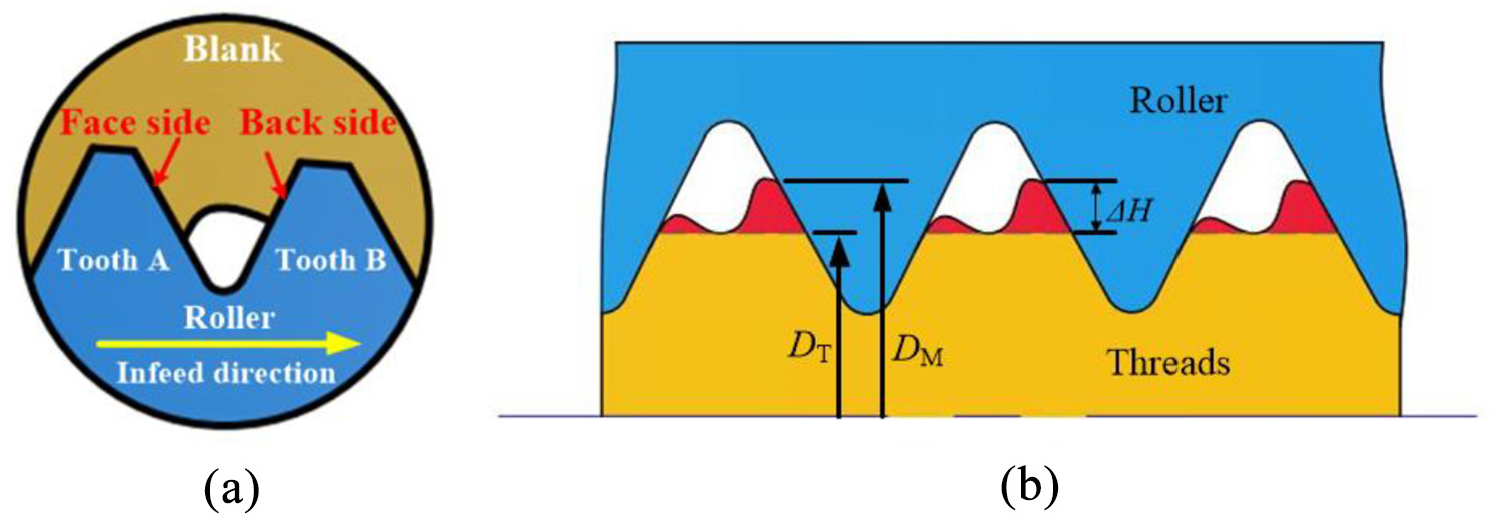
The forming process of tooth: (a) the schematic of tooth formation and (b) height distribution of the protrusion.
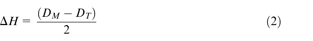
The protrusion size in the thread forming process has a significant effect on the performance of the threads. It is necessary to define an index to evaluate the forming process of the protrusion under different conditions. As shown in Figure 6(b), the red region indicates the protrusion and the diameter of the formed threads from the top of the protrusion and from the bottom of the protrusion are DM and DT, respectively. The height ΔH of the protrusion is selected as an index to evaluate the effect on performance of the threads, which is calculated by equation (2)
The protrusion formation process
The P1, P2, P3, and P4 locate on the top of the tooth and are applied to investigate the protrusion formation process. The tooth profile at different rolling times is displayed in Figure 7.
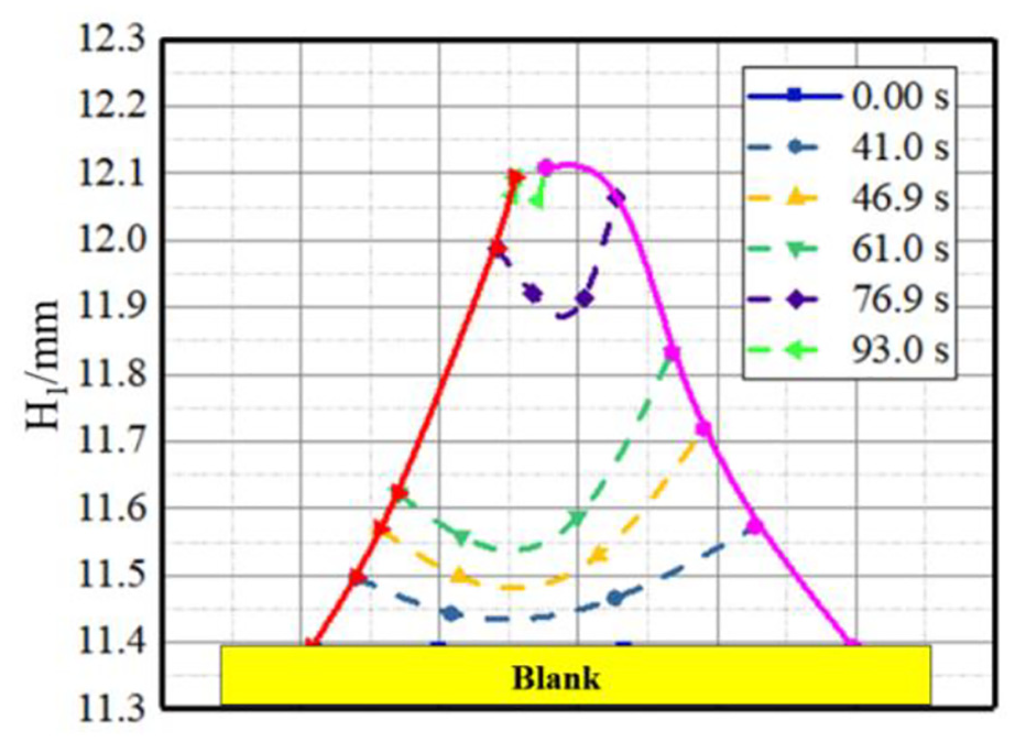
Tooth profile during the rolling process.
The tooth profile was plotted by the point position at different times. Both tooth flanks are taller while the middle of the tooth profile is lower. There are two protrusions at the top of the tooth, which are caused by the higher material flow velocity of tooth flanks. Besides, with the formation processing, the height of the protrusion keeps changing.
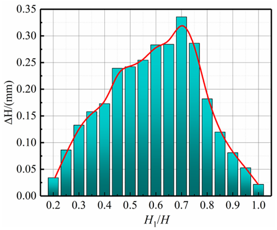
The variable H1 is the height of formed tooth profile which is defined as the height from the bottom of tooth to P4 and H is the full tooth height. As shown in Figure 8, the horizontal axis represents the ratio of the formed tooth height H1 and the full tooth height H, and the longitudinal axis represents the protrusion height ΔH. With the increase in the tooth height, the protrusion height ΔH increases gradually, reaching the maximum value of 0.326 mm at the ratio of 73%. After the peak, as the forming process continues, the height difference ΔH gradually decreases to its minimum value.
Height of the protrusion in rolling process.
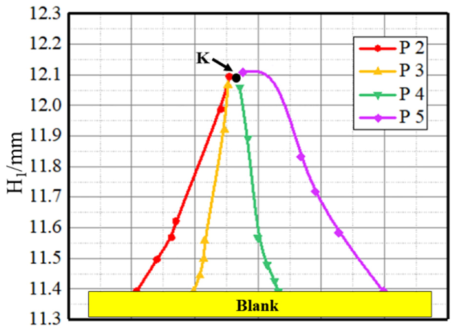
The point tracks of P1, P2, P3, and P4 during the rolling process are shown in Figure 9. The tracks of P2 and P3 are approximately straight lines, and the tracks of P1 and P4 are along the flanks of the roller tooth. The points finally close at the region K. The position of the region K locates near the back side of the tooth. This phenomenon is also caused by the different material flow velocities on two flanks of the tooth during the forming process.
Point tracks in rolling process.
The effects on the protrusion in the forming process
Protrusion is a typical defect in threads, which is closely related to the material of the blank and structure of the roller. The effects of different blank materials and the pre-rolling angles on the protrusion are analyzed in detail in the following section.
Protrusion formation with different pre-rolling angles of roller
For the roller, the pre-rolling angle α1 is an important parameter, which was selected to investigate its effect on the protrusion. The pre-rolling angle was set at 2°, 5°, and 8°, respectively. The maximum height (ΔHmax) of the protrusion on the face side and the back side was counted in the whole forming process.
The maximum heights of the protrusion under different pre-rolling angles are shown in Figure 10. With the increase in the pre-rolling angle, the maximum height of the protrusion also increases on both sides of the tooth. And the change of ΔHmax in the face side is larger than that in the back side. When the pre-rolling angle increases, the forming time is shortened and the deformation of the blank goes more drastic, leading to higher velocity of the material flow and protrusion height. So, the pre-rolling angle needs to be small for good performance of the threads.
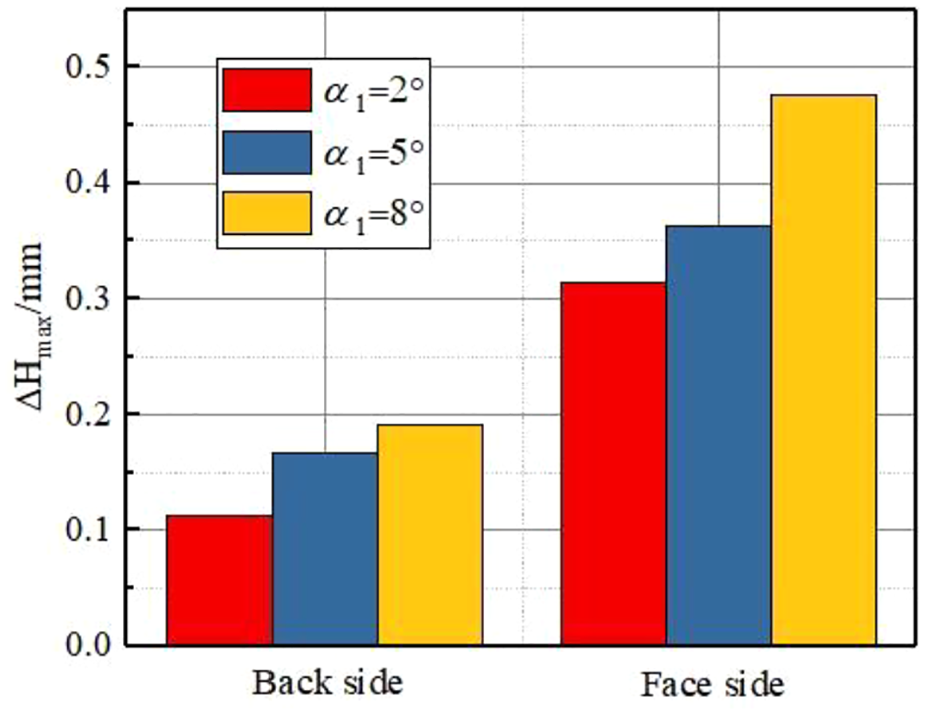
Height distribution of the protrusion under different pre-rolling angles.
Protrusion formation with different materials of the blank
Protrusion formation in copper was simulated by the finite element model, and the pre-rolling angle of the roller was 2°. The Johnson–Cook constitutive model was applied and the parameters are shown in Table 1. In order to compare the height of the protrusion, the boundary conditions are set the same as the forming threads with the medium carbon steel AISI 1045. The maximum heights (ΔHmax) of the protrusion with copper and medium carbon steel AISI 1045 are 0.365 and 0.326 mm, respectively. ΔHmax of the protrusion with copper is larger than that with medium carbon steel AISI 1045.
This phenomenon can be explained in two aspects. One aspect is the friction in the rolling process. During the forming process, the tooth is gradually taller and friction is produced. The friction can be described as shear friction in equation (3)

where m is the friction factor, and k is the shear yield strength.
For the copper and AISI 1045, the friction factor m is not so different. But the shear yield strength of AISI 1045 is much larger than that of copper. When the tooth is higher, there is larger friction of AISI 1045 than that of copper. The friction prevents the deformation, leading to lower protrusion of AISI 1045. The other aspect is the material hardening exponent. Copper has larger material hardening exponent than AISI 1045. In the forming process, the AISI 1045 has better uniformity of deformation. So, the protrusion of AISI 1045 is lower.
Experimental verification and analysis
The experiments were carried out on self-developed equipment which mainly included the servo motor, the reducer, the rolling device, and so on, as shown in Figure 11(a). The servo motor serves as the power that drives the blank rotation. The reducer increases the forming torque. When the blank is rotating, the rolling device moves along the linear guide and the material flow occurs on the surface of the blank. The rolling device is the most important part for the rolling process. It contains the rollers and other accessories, which are shown in Figure 11(b).
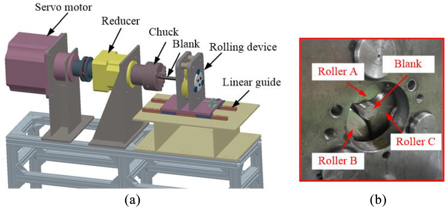
Thread rolling equipment: (a) the structures of the equipment and (b) the rolling device.
In these experiments, the conditions are the same as those in the finite element analysis. The rotation speed of the blank is 10 r/min. The material is the medium carbon steel AISI 1045 and copper. The material of rollers is Cr12MoV.
The formed threads are shown in Figure 12(a). The threads were cut along the axial cross section by wire electrical discharge machining (WEDM), and the appearance of the tooth profile was observed.
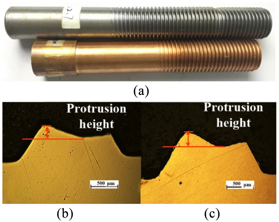
The formed threads and the comparison of formed protrusion: (a) the formed threads, (b) protrusion with AISI 1045, and (c) protrusion with copper.
The same regions of threads with different materials were selected to observe. Figure 12(b) and (c) shows the comparison of formed protrusion with AISI 1045 and copper. There are two protrusions on the top of the tooth profile, and the height of the protrusion is different. The shapes of the formed protrusion with the two materials are similar.
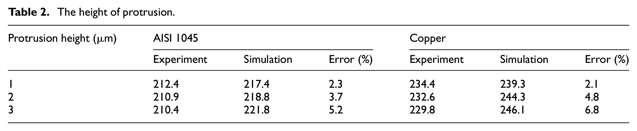
The quantitative comparison was done for the verification. Three different teeth were, respectively, measured five times. The average protrusion height was selected as evaluation in Table 2. The results of the simulation approximate the results of experiments.
The height of protrusion.
The material of threads is the medium carbon steel AISI 1045, and the tooth profiles in 43% tooth height and 67% tooth height are shown in Figure 13(a) and (b). According to the figure, the protrusion appears asymmetrically on both flanks of the tooth. The protrusion on face side is taller than that on back side. And in different forming times, the protrusion height is varying. Figure 13(c) shows the tooth profile of threads formed with the copper, in which the closed region K is shown, which is close to the back side. This phenomenon is caused by different material flow velocities on tooth flanks. The closed region is easy to form a defect. Figure 13(d) shows the enlarged view of the region K, where an obvious gap can be observed.
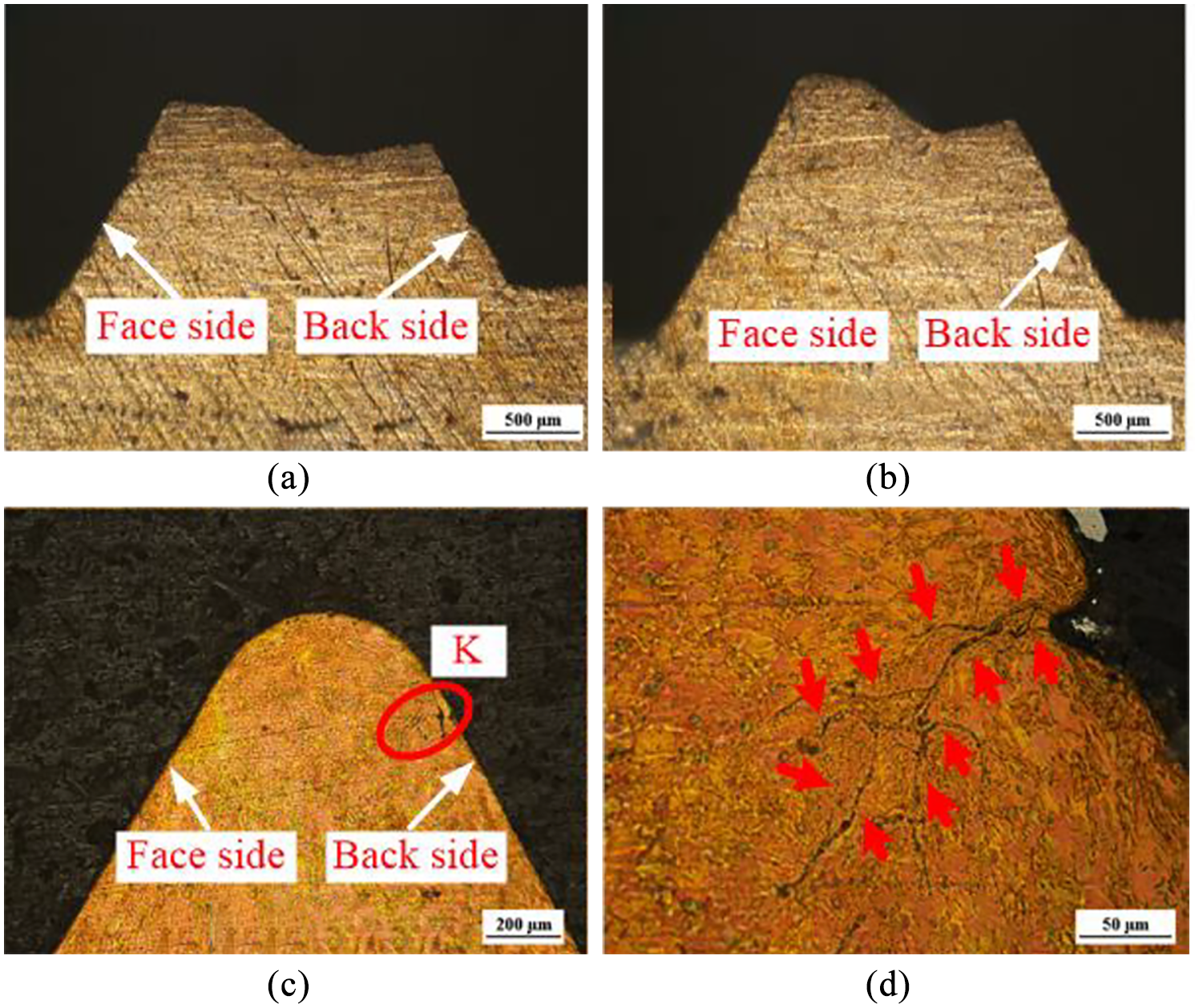
Experimental verification: (a) tooth profile in 43% tooth height, (b) tooth profile in 67% tooth height, (c) the closed position K, and (d) the enlarge of the closed position K.
In order to prevent the closing defect, the pre-rolling angle should be 2° and the lubrication is required to reduce the friction.
Conclusion
Through analysis on the protrusion formation mechanism and the influential factors in thread forming by axial self-infeed rolling process, conclusions are listed as follows:
The axial motion of the rollers squeezes the face side of the tooth, leading to the higher velocity of material flow on the face side, and also results in the protrusion on the face side is taller than that on back side.
During the rolling process, the height of the protrusion is changed, and it increases first and then decreases. The maximum height of the protrusion appears at 73% full tooth height.
With the increase in the pre-rolling angle, the protrusion height also increases and copper easily forms larger protrusion. For the same material, in order to minimize the protrusion size, the pre-rolling angle should be 2°.
The position of the closed gap is located on the upper top of the formed thread tooth, close to the back side. The results of the finite element analysis approximate the experimental results.
Footnotes
Declaration of conflicting interests
The author(s) declared no potential conflicts of interest with respect to the research, authorship, and/or publication of this article.
Funding
The author(s) disclosed receipt of the following financial support for the research, authorship, and/or publication of this article: This work was supported by the National Natural Science Foundation of China for Key Program (grant no. 51335009) and the State Key Laboratory of Materials Processing and Die & Mould Technology, Huazhong University of Science and Technology (grant no. P2019-028).