
Abstract
With the demand of the larger cutting forces and the more precise prediction of the performance of the spindle, the angular stiffness of the ultra-high-speed spindle should be taken into consideration. In this article, a 5-degree-of-freedom model of the aerostatic spindle is established by considering the one set of the thrust bearing and journal bearing together with the modified discharge coefficients in high-speed condition. Furthermore, static characteristics including angular stiffness of the high-speed aerostatic spindle are obtained in terms of different angular displacements and different operational parameters. The angular displacement effects are revealed and the optimum air film thickness for both thrust gas bearings and journal gas bearings is given for ultra-high aerostatic spindle design.
Keywords
Introduction
The aerostatic bearings are widely used in the micromachining, which demands high precision and works in high-speed (5000–100,000 r/min) or ultra-high-speed condition (above 100,000 r/min).1,2 Taken air as lubricant, the bearing system has advantages such as low friction, low noise, high accuracy and high reliability in high-speed working condition. However, the applications of aerostatic bearings are limited because of their inherent disadvantages as low load capacity and low stiffness compared to other bearings.
The aerostatic bearing system usually consists of one or two sets of thrust bearings and journal bearings. Many researchers focus on the static performance of these bearings and pay effort on optimizing the load capacity and stiffness of the bearings by changing the geometry parameters and operational parameters. Kassab et al. 3 investigated the load capacity of the aerostatic rectangular recess bearings experimentally and proved that the load capacity can be promoted by increasing the diameter of the supply holes. Lo et al. 4 proposed a detailed numerical study on the static characteristics of air bearings including the pressure distribution, load capacity and mass flow rates with different film clearances, eccentricity ratios and gas supply pressure. Belforte et al. 5 analyzed stiffness of the externally pressurized grooved gas thrust bearing with different groove depths and proved that the stiffness can be enhanced with the increment of the supply pressure and the groove depth. Miyatake and Yoshimoto 6 and Nishio et al. 7 showed that the thrust bearings with small feed holes have similar stiffness to the compound restrictors and high damping coefficients. Wu et al. 8 designed an aerostatic spindle with high carrying capacity, which is used for large-precision drum lathe. They found that the throttling effect has positive influences on promoting the load capacity and stiffness.
With the demand for higher efficiency of manufacturing, the air bearings working in ultra-high-speed conditions are designed and studied in different geometry/operational parameters. Bang and Lee 9 designed a thrust bearing working in ultra-high-speed up to 100,000 r/min and introduced the static and dynamic analyses on the bearing which considers the centrifugal force. Su and Lie 10 investigated the rotation effects on the hybrid air journal bearings and the porous air journal bearings and found that under high speed, the load capacity grows faster with the growth of the eccentricity ratios. Morosi and Santos 11 established a model of hybrid gas journal bearings and demonstrated that the aerostatic pressure contribution should be enhanced to get larger load capacity and wider operational speed range. Gao et al. 12 introduced a computational design platform for analyzing the static performance of both thrust air bearings and journal air bearings by solving the Reynolds equations using finite element method (FEM). Wang et al. 13 found that the principal dynamic stiffness of the hybrid gas journal bearings can be increased with the growth of the rotational speed. The finite difference method (FDM) is adopted in their study to solve the unsteady Reynolds equations. Song et al. 14 proposed modified terms on the formulation of discharge coefficients by considering the rotation effects and varied film thickness, which is verified according to the experiments.
The above literatures mostly focus on the translational motions of the air bearing system and neglect the tilting motions of the air bearings, especially in the high-speed area. Nakamura and Yoshimoto 15 studied the static and dynamic tilt characteristics of the aerostatic thrust bearings and found that the larger groove length and depth could conduct larger tile moment. Dal and Karacay 16 showed that the angular misalignment could change the pressure distribution and thus has influence on the load-carrying capacity. They established a 5-degree-of-freedom (DOF) air bearing model but did not take the thrust bearing into consideration and did not analyze the angular stiffness in different speed conditions. Cui et al. 17 investigated the angular stiffness of the aerostatic bearing systems including one set of thrust bearing and journal bearing numerically and experimentally. They found that the angular stiffness is affected by the film thickness, orifice diameter and eccentricity ratios. However, the model is established under zero rotational speed and thus zero attitude angle, which is a 3-DOF model.
In the high-speed condition, the rotating shaft gets the equilibrium position at a non-zero attitude angle. As a result, in this article, a 5-DOF model of both thrust air bearing and hybrid gas journal bearings is established to calculate both angular stiffness around x- and y-axis. The load capacity and the translational and tilt stiffness are calculated by solving the Reynolds equation with FEM in which the modified Cd in different speed conditions is adopted. Furthermore, the influence of the different speeds, eccentricity ratios and geometry parameters on the static characteristics are also studied and discussed.
Mathematic model
5-DOF model and mass flow model with modified discharge coefficients
The typical configuration of the ultra-high-speed aerostatic spindle is illustrated in Figure 1. There are two sets of hybrid gas journal bearings and one set of thrust bearings which support the radial stiffness, axial stiffness and angular stiffness. The air with supply pressure (Ps) flows through the orifice and then reduces to the downstream pressure (Pd). The mass flow rates of the orifice are then deduced according to the formula of the ideal nozzle
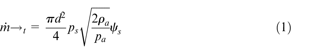
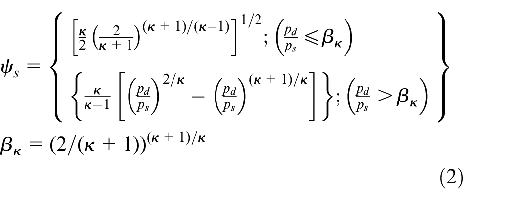
where d is the diameter of the orifice, pa is the atmosphere pressure, ρa is air density in the atmosphere and κ is the entropic expansion index and equals to 1.4 for air. And Cd is the discharge coefficients which represents the correction between the theoretical results and the actual results.
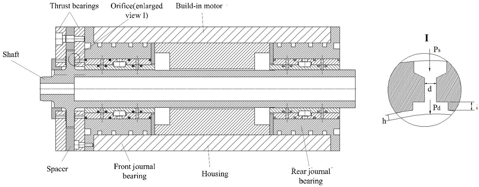
Configuration of the ultra-high-speed aerostatic spindle.
For the thrust bearings in which the gas film is almost uniform, the Cd can be denoted as 18

While in the hybrid gas journal bearings, the discharge coefficient should be the function of the rotational speed and the eccentricity ratios and is denoted using the results of 14
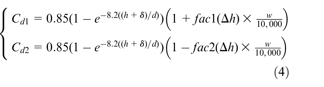
where Cd1 and Cd2 represent the discharge coefficient of the upstream orifice and downstream orifice, respectively.
In order to calculate the static performance of the ultra-high-speed air spindle including the translational stiffness and angular stiffness, a 5-DOF model is established for both thrust bearings and journal bearings, as depicted in Figure 2. The shaft rotating in the speed of w gets the equilibrium position with non-zero dx and dy in hybrid gas journal bearings. The dz in the z-direction provides the stiffness of the thrust air bearings. Meanwhile, the external force applied at the top of the shaft causes the angular displacement θx and θy around x- and y-direction, respectively.
Schematic view of ultra-high-speed air bearings with 5-DOF.
As a result, we could deduce the air film thickness in the 5-DOF model according to the geometry relationships in Figure 2. The air film thickness of thrust bearings can be denoted as
The air film thickness in the front journal bearings is represented as
The air film thickness in the rear journal bearings is represented as
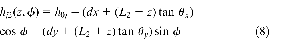
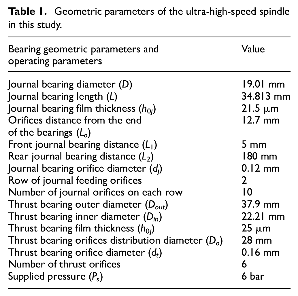
where h0t and h0j are the average film thickness in the thrust bearings and journal bearings, respectively; L1 and L2 represent the distance between the front journal bearing and the rear journal bearing to the origin point, respectively. The geometry parameters and supply parameters in this study are listed in Table 1.
Geometric parameters of the ultra-high-speed spindle in this study.
Governing equations and FEM discretization
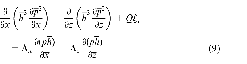
With the assumption that the curvature of the air film is negligible, the air film in the hybrid journal bearings can be expanded into a two-dimensional plane and the steady-state dimensionless Reynolds equation in hybrid gas bearings can be written as
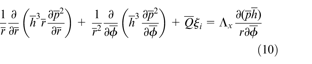
In thrust air bearings, the steady-state dimensionless Reynolds equation should be deduced in the Column coordinates as
The above dimensionless parameters are defined as
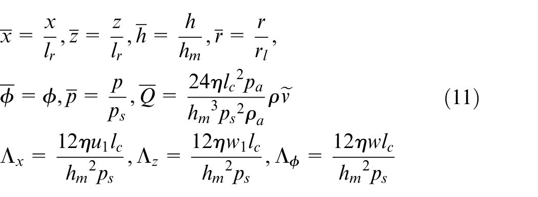
where x, z, r and
In addition, by substituting the pressure square function

and the coordinate transform equation

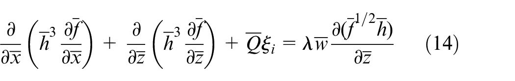
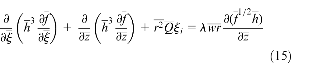
to equations (9) and (10), the derived equations for journal bearings and thrust bearings are thus shown as
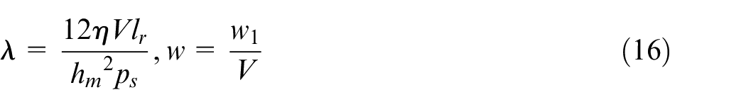
where λ represents the bearing number and
Both the hybrid journal bearings and the thrust gas bearings can be transformed to the rectangular domain, as depicted in Figure 3. The circumference θ is substituted for z′, which is divided into nz parts while z-direction (while r-direction in the thrust bearings) is substituted for x′ and is divided into nx parts. Because of the asymmetry of the structure, the whole domain of the journal bearings and the thrust bearings are meshed and calculated.
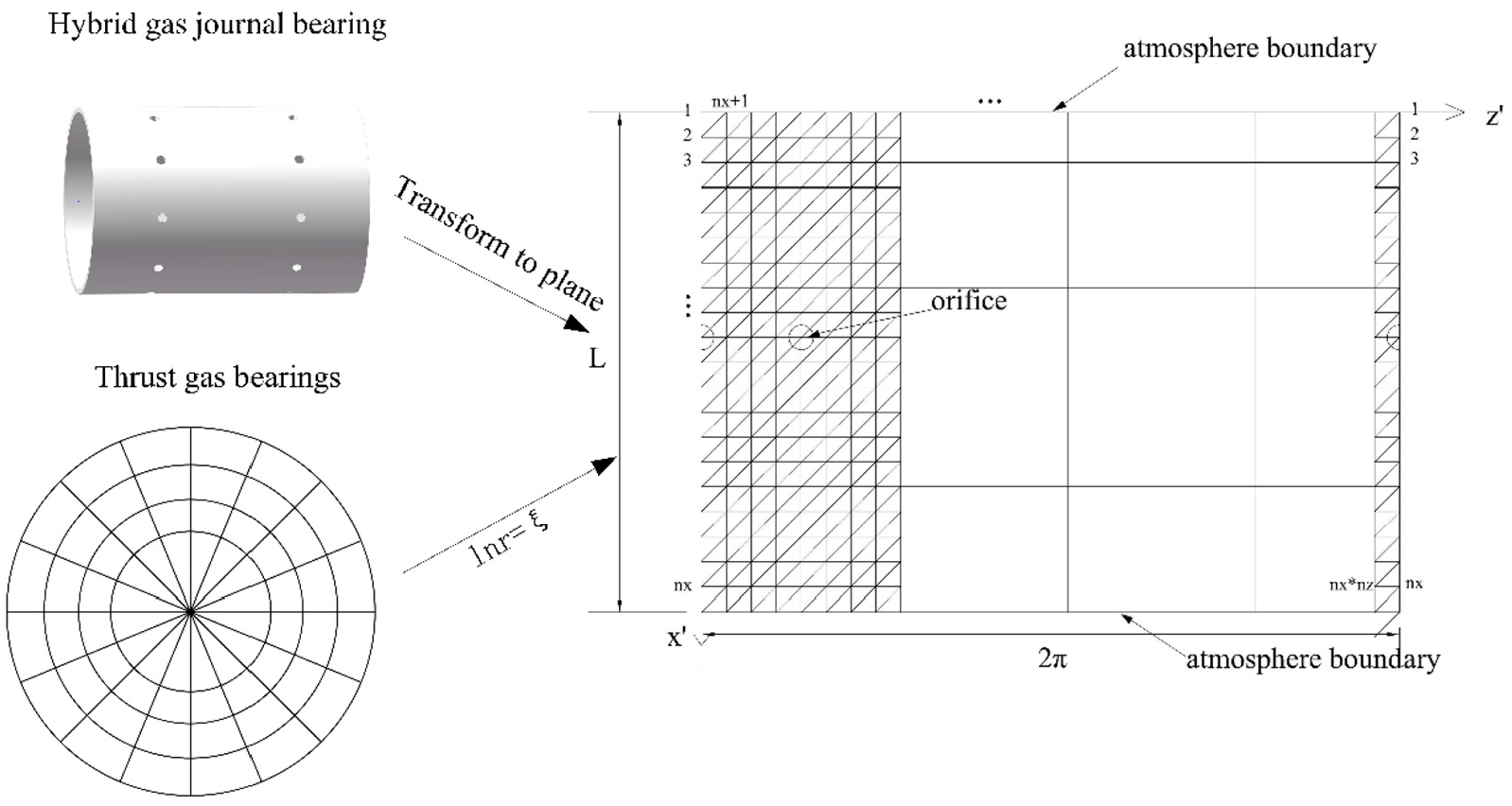
Computational domain of hybrid air journal bearing.
The FEM is adopted to solve equations (14) and (15) under the atmosphere boundary condition and orifice boundary condition


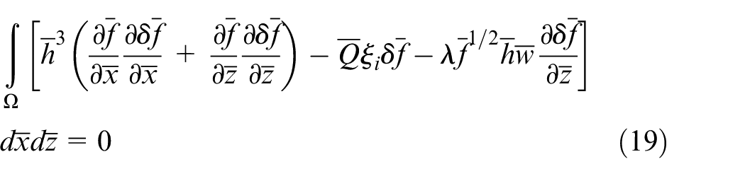
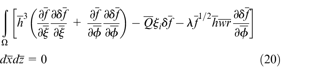
Galerkin’s weighted residual method is applied and the weak solution of equations (14) and (15) can be deduced as
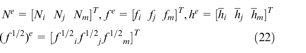
Next, the interpolation function is introduced as

where
In the triangular element shown in Figure 3, we could deduce
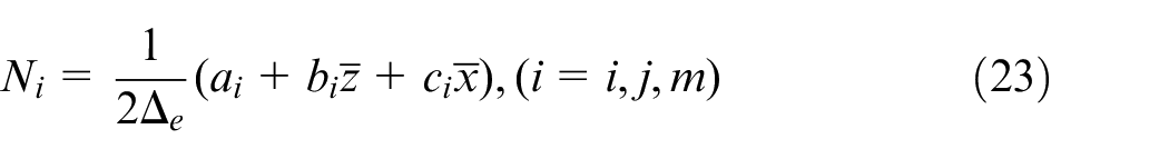
where
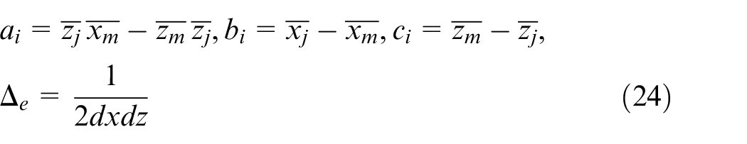
It is noted that in the thrust bearings,
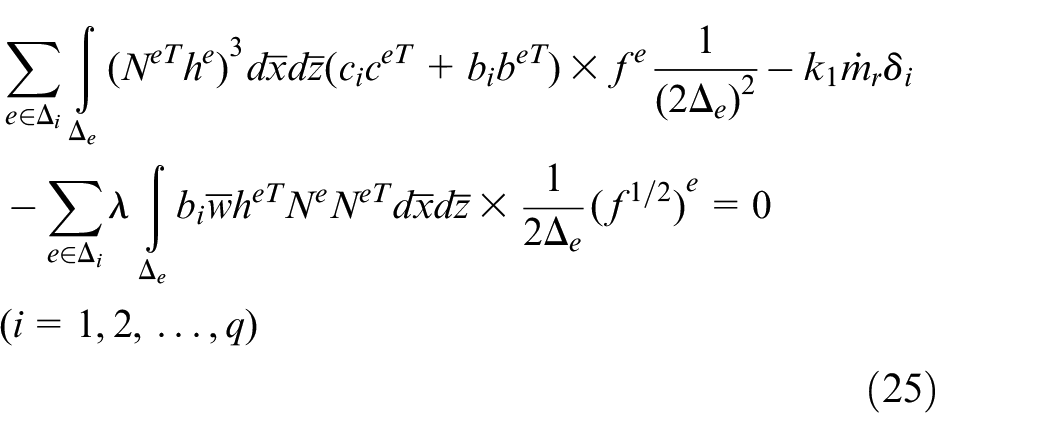
and for the thrust bearings
where
Calculation of the static characteristics
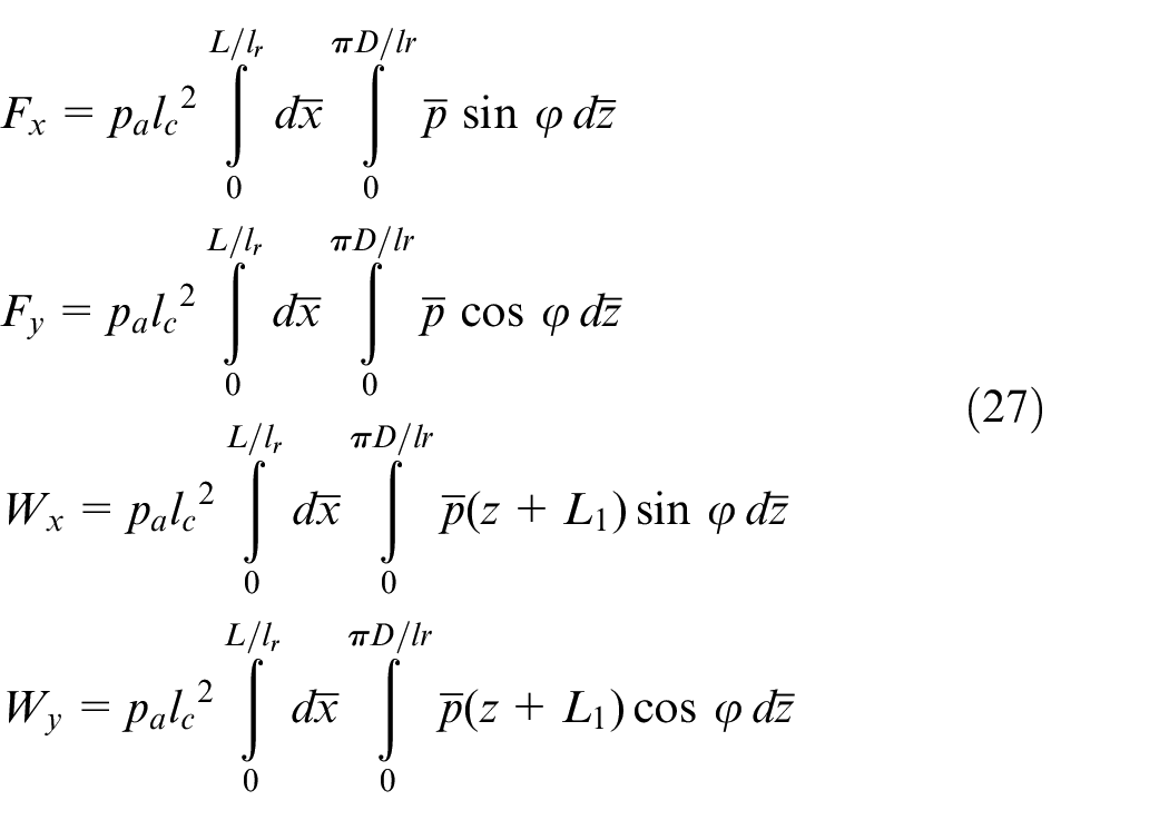
Finally, the carrying capacity Wx and Wy together with the angular torque in the journal bearing can be calculated from the following
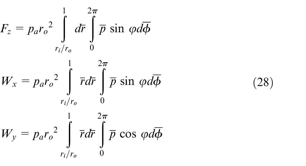
while in the thrust bearing
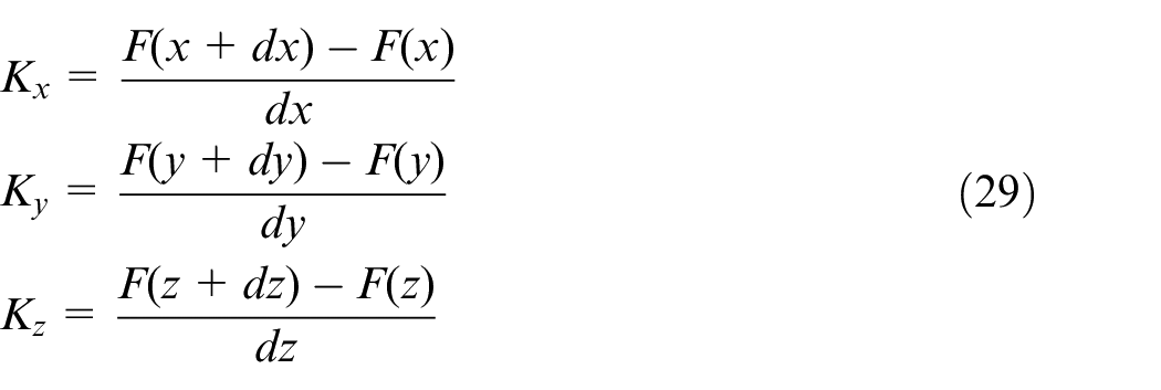
Thus, the translational stiffness in x-, y- and z-direction of the ultra-high-speed air spindle can be obtained as
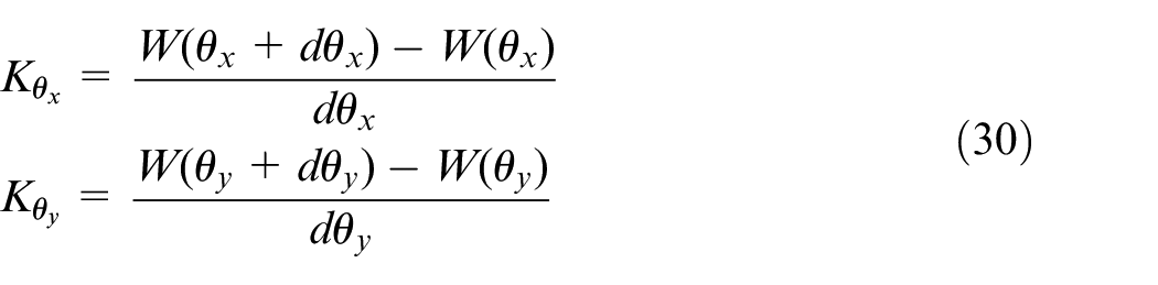
and the angular stiffness in the direction of the θx and θy can be expressed as
MATLAB® codes are employed to solve the equations deduced by equation (26). The convergence criterion of this study is
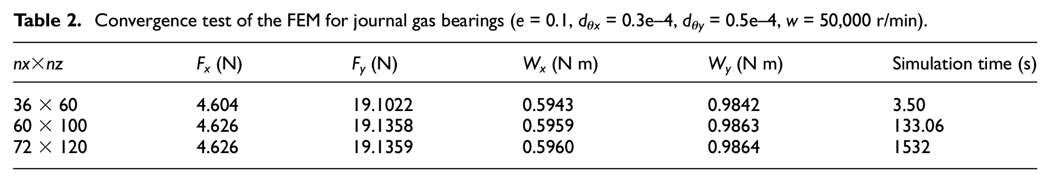
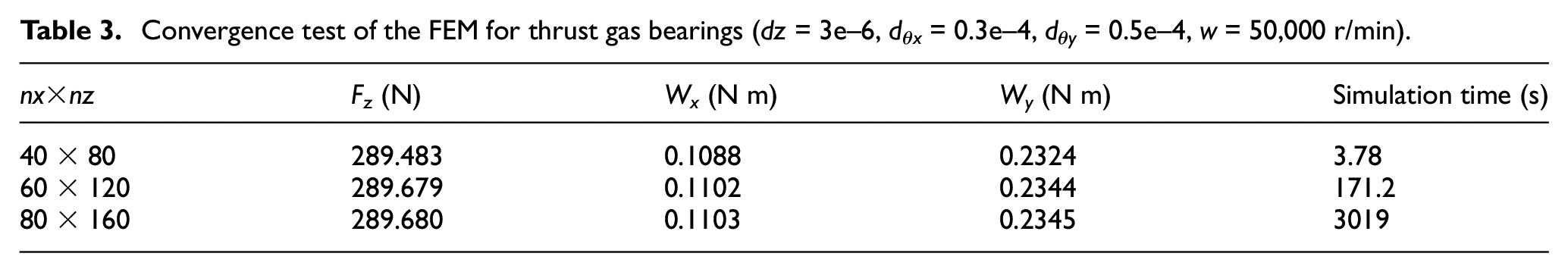
and by increasing the density of the mesh, the static performances of ultra-high-speed aerostatic spindle are also converged in the convergence test, as shown in Tables 2 and 3. Besides, the simulation time under the variation of the mesh size is listed in the table. It is noted that the simulation time varies according to the performance of the computer, but the comparison between different mesh sizes can provide reference for programming.
Convergence test of the FEM for journal gas bearings (e = 0.1, dθx = 0.3e–4, dθy = 0.5e–4, w = 50,000 r/min).
Convergence test of the FEM for thrust gas bearings (dz = 3e–6, dθx = 0.3e–4, dθy = 0.5e–4, w = 50,000 r/min).
In this study, to obtain the static performances including the translational stiffness and angular stiffness of the whole bearing system of the ultra-high-speed spindle, the Reynolds equations without angular displacement are solved first and the steady attitude angles are obtained. Then the angular displacements are added to the film thickness and the equations are solved sequentially. The discharge coefficients are updated according to the eccentricity ratios and rotational speeds. The flow chart of numerical calculation is shown in Figure 4.
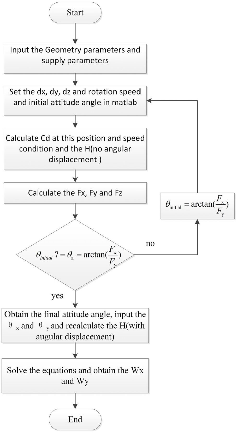
The solving process of obtaining the static and dynamic performances of gas journal bearings.
Results and discussion
The experimental results from Cui et al.’s 17 study are utilized as a comparison to validate the proposed numerical method in this study. These results are angular torque under the variations of the deflection angle in an aerostatic spindle with one set of thrust gas bearing and one set of journal gas bearing. Figure 5(a) and (b) compares the numerical results of constant Cd and modified Cd with the experimental results at the supply pressure of the 5 and 6 bar, respectively. It can be found that for both supply pressure, the numerical results with modified Cd method are in good agreement with the experimental ones, which indicates the correctness of the method. Specifically, the angular stiffness relative error between the numerical results both with modified discharge and with constant coefficients is listed in Table 4. It is shown that the model with modified Cd underestimates the angular stiffness and gets lower relative error. It can also be shown that the results with constant Cd overestimate angular stiffness for both supply pressure, which is consistent with the translational stiffness results from Song et al. 14
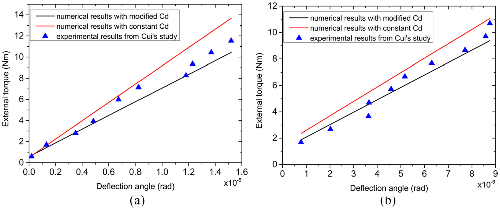
Static angular stiffness of aerostatic spindle comparison between Cui’s experiment and this study (with constant Cd and modified Cd): (a) under the supply pressure of 5 bar and (b) under the supply pressure of 6 bar.
Relative error of both models with modified Cd and constant Cd in comparison with experimental results of angular stiffness.
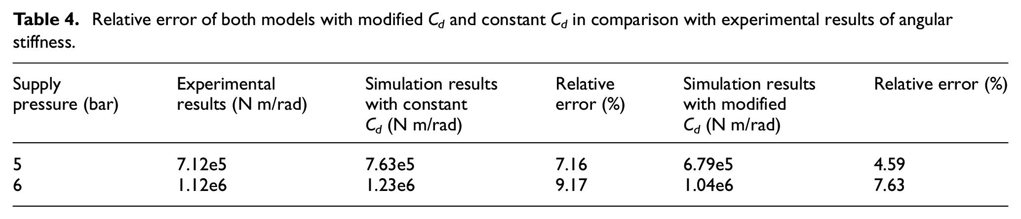
Figure 6 shows the influences of the discharge coefficients on the pressure distribution of both gas journal bearings and gas thrust journal bearings at the rotational speed of 50,000 r/min. By adding the modified function to the Cd in the gas journal bearings, the upstream pressure can be enhanced while the downstream pressure has the opposite tendency, as depicted in Figure 6(a) and (b). This phenomenon is more obvious in the angular displacement of the spindle because the angular displacements indeed increase the eccentricity in the A-A section, as shown in Figure 2. Figure 6(c) and (d) shows the pressure distribution in thrust gas bearing in circumferential direction and radial direction. It can be seen that the pressure calculated by two methods are similar in non-angular displacement because the discharge coefficients remain constant in the constant film thickness. In addition, at the angular displacement of 0.5e–4 rad, the differences are less obvious than those in the journal bearings because the variation of the film thickness in the thrust bearings is lower with no eccentricity.
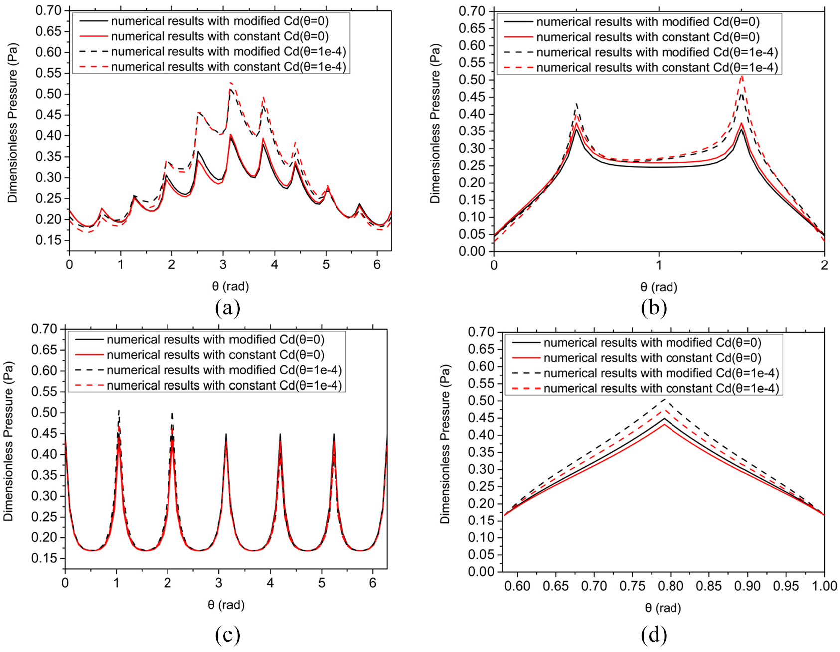
Pressure distribution of both journal gas bearings and thrust gas bearing under two methods: (a) pressure distribution at A-A section in journal gas bearing, (b) pressure distribution at B-B section in journal gas bearing, (c) pressure distribution at C-C section in thrust gas bearing and (d) pressure distribution at D-D section in thrust gas bearing.
Figure 7 illustrates the load-carrying capacity and attitude angle of gas journal bearings under the variation of the rotational speeds. At the condition without angular displacement, the load capacity of the bearings grows with the increment of the speeds and the eccentricity ratios. And the attitude angles first grow to a peak value and remain constant or grow very slowly with the increasing speeds, as shown in Figure 7(a) and (b). Furthermore, Figure 7(c) and (d) demonstrates that the pressure distribution is changed both in the circumferential direction and in the axial direction by adding the angular displacement at the equilibrium position. At the position of θx = 0.5e–4 and θy = 0.5e–4, the differences in the circumferential are enhanced because the θx increases the eccentricity ratios and the position of maximum pressure is changed because the θy changes the position of the minimum film thickness in the circumference. As a result, the load capacity is enhanced with the growth of the angular displacement where the dθy has larger influences than dθx, as depicted in Figure 7(e). This is because the dθy changes the position of minimum air film thickness and the load capacity in the x-direction is thus enhanced remarkably. Figure 7(f) also verified the conclusion that the θx has little influence on the attitude angles while the θy changes the attitude angles notably.
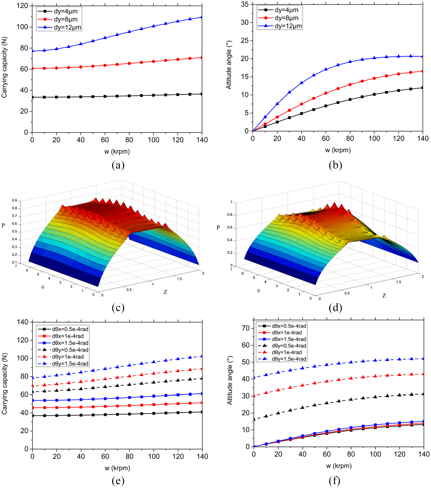
Load capacity and attitude angle under the variation of the rotational speed in hybrid gas journal bearings: (a) load capacity with different dy (θx = 0, θy = 0); (b) attitude angle with different dy (θx = 0, θy = 0); (c) dimensionless pressure distribution with no angular displacement; (d) dimensionless pressure distribution at θx = 0.5e–4, θy = 0.5e–4; (e) load capacity with different θx and θy; (f) attitude angle with different θx and θy.
Figure 8 shows the static performances of thrust gas bearings with grooves in variation of the rotational speeds. The rotational speeds have little influences on the load capacity at the low dx of the spindle while the load capacity grows slowly with the increment of the rotational speeds at high dx, as depicted in Figure 8(a). In terms of angular displacement, the load capacity of the thrust bearings increases with the growing rotational speed. Moreover, the larger angular displacement will induce larger load-carrying capacity, as shown in Figure 8(b). Because of the symmetry of the structure, the θx and θy have almost the same influences on the static performance of the thrust bearings. It is noted that the load-carrying capacity shown in Figure 8(a) and (b) is calculated by considering two opposite thrust bearings. Figure 8(c) and (d) demonstrates the pressure distribution without and with the angular displacement, respectively. It can be observed that at the θx = 0.5e–4, θy = 0.5e–4, the minimum of the air film thickness and the maximum the pressure are reached at the line that is 45° to x-direction.
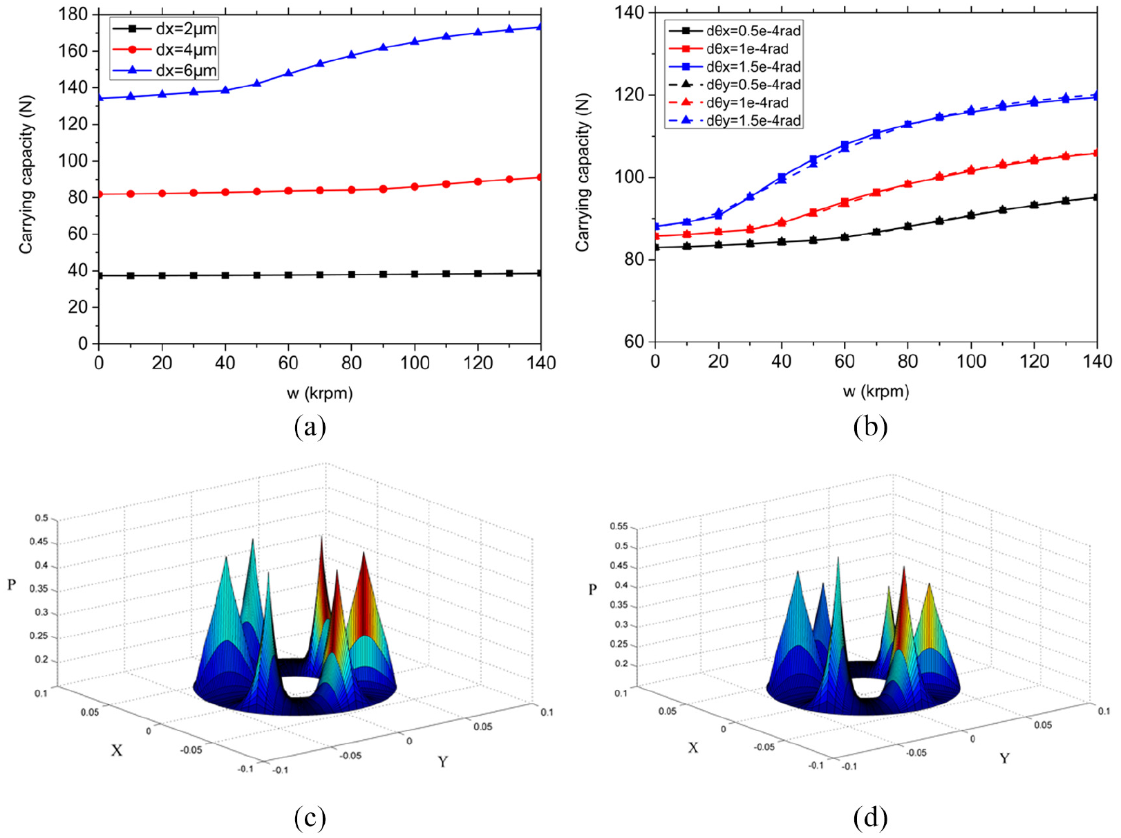
Load capacity and attitude angle under the variation of the rotational speed in gas thrust bearings: (a) load capacity with different dy (θx = 0, θy = 0), (b) load capacity with different θx and θy (dx = 4 µm), (c) dimensionless pressure distribution with no angular displacement and (d) dimensionless pressure distribution at θx = 0.5e–4, θy = 0.5e–4.
In terms of stiffness of 5-DOF of both journal gas bearings and thrust gas bearings, Figures 9 and 10 illustrate the stiffness including Kxx, Kyy, Kz, Kθx and Kθy with different air film thicknesses. In variation of the rotational speeds, the stiffness in x- and y-direction remains constants with higher gas film thickness. The x- and y-direction stiffness increases with the increment of the rotational speed in the journal bearing with gas film thickness of 10 µm. While for the journal bearing with gas film thickness (h = 12 µm), the Kxx increases with the growth of the rotational speeds and the Kyy first increases to a peak value and then decreases, as shown in Figure 9(a). It can be explained that in the small film thickness, the aerodynamic effects are enhanced evidently and the forces in the x-direction are promoted. Meanwhile, the forces in the y-direction are weakening at the high speed because of the high attitude angle in the journal gas bearings, which lead to the decline in the stiffness. As for the angular stiffness, the variation of the rotational stiffness Kθx and Kθy is also not obvious at high film thickness. However, at the small gas film thickness, the Kθx increases to a value and then remains constants and the Kθy continues to decrease with the growth of the rotational speeds, which means the low gas film thickness may not be suitable for ultra-high-speed spindles with high angular stiffness requirements. Figure 9(c) and (d) shows the Kxx/Kyy and Kθx/Kθy in different eccentricity displacements/angular displacements under the rotational speeds of 50,000 r/min. It can be found that with the increment of the eccentricity displacement, the stiffness with low air film thickness continues to decrease while those with high air film thickness increase slowly for both Kxx and Kyy. In addition, for all gas film thickness, the Kθy is not influenced by the angular displacements while Kθx first remains constants and increases sharply with the growth of the angular displacements, which will lead to unstable problems of the systems. As a result, the maximum angular displacement for the journal bearing thickness is less than 1.1e–4 rad.
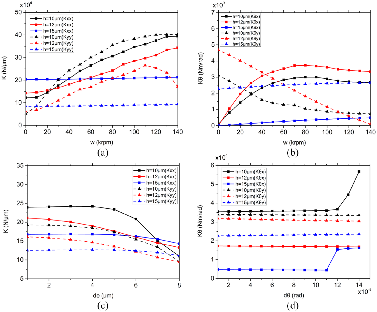
Stiffness of hybrid gas journal bearings with different air film thicknesses: (a) Kxx and Kyy under the variations of rotational speeds, (b) Kθx and Kθy under the variations of rotational speeds, (c) Kxx and Kyy under the variations of eccentricity displacements and (d) Kθx and Kθy under the variations of angular displacements.
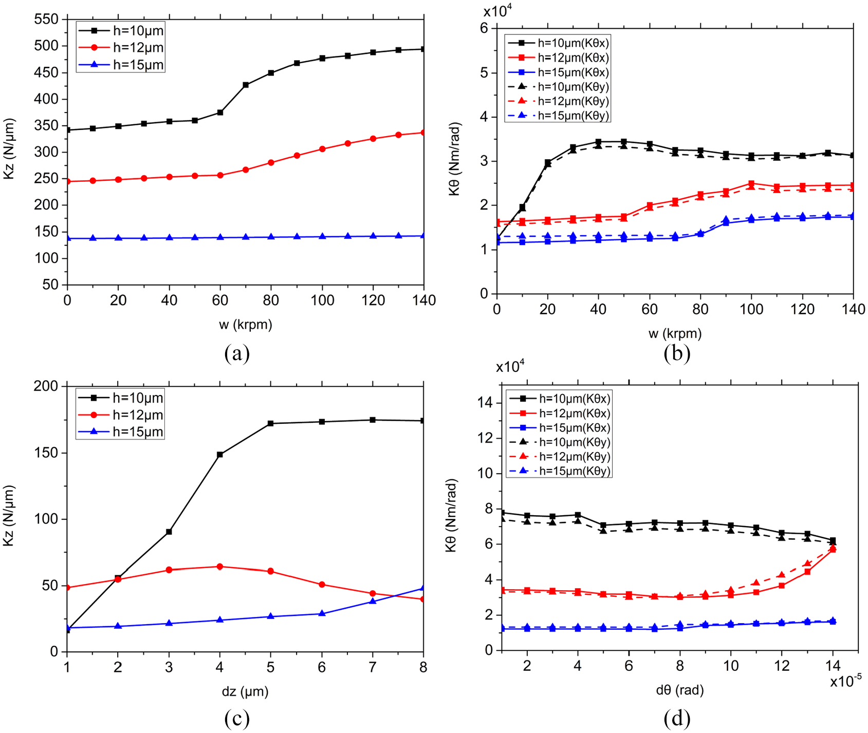
Stiffness of gas thrust bearings with different air film thickness: (a) Kz under the variations of rotational speeds, (b) Kθx and Kθy under the variations of rotational speeds, (c) Kz under the variations of dz and (d) Kθx and Kθy under the variations of angular displacements.
The stiffnesses (Kz, Kθx and Kθy) have similar tendencies with those in hybrid gas bearings under the variations of the rotational speeds, as depicted in Figure 10(a) and (b). The stiffness with large film thickness remains stable with the growth of the rotational speeds. For the journal bearings with small film thickness, the growth rate of the stiffness in z-direction is low before the rotational speeds are less than 60,000 r/min and then continues to grow with the increment of the speeds. The Kθx and Kθy obtain the maximum values at the speed of 50,000 r/min and then decline slowly, as depicted in Figure 10(b). Figure 10(c) demonstrates that the stiffness with small gas film thickness has the optimum stiffness in different eccentricity displacements and the stiffness with the large film thickness grows under the growth of the displacements. It can be seen that for small film thickness, the stiffness first grows to a peak value and then remains constant with the growth of the dz. Also, the angular stiffness with small thickness rises sharply with a growth of the displacement angles, as depicted in Figure 10(d).
By comparing Figures 9 and 10, it can be concluded that the angular stiffness of the bearing system is mainly provided by thrust gas bearings. For the design of the journal gas bearings and thrust gas bearings, it is suitable to choose a film thickness of about 12 µm to obtain a stable and large stiffness for each freedom.
Conclusion
In this article, the static characteristics in 5-DOF of both journal gas bearings and thrust gas bearings under ultra-high speeds are studied thoroughly. The FEM with modified Cd is used to solve the Reynolds equations and is verified by comparing with the experimental results from other studies. The effects of modified discharge coefficients are revealed and demonstrated from the pressure distribution in both bearings under high-speed conditions. The static performances of the ultra-high-speed aerostatic spindle are also discussed under different working conditions. Furthermore, the 5-DOF stiffness of the journal gas bearings and thrust gas bearings are investigated under varied working conditions with different air film thicknesses. The following conclusions can be drawn:
The modified Cd FEM gives predictions that are more precise on the angular stiffness of the aerostatic bearings. The constant Cd FEM overestimates the pressure in the upstream and underestimates the pressure downstream. And this phenomenon is more obvious in the journal gas bearings with the larger eccentricity ratios.
The angular displacements θx and θy influence the carrying capacity and the attitude angles of the journal gas bearings under the variations of rotational speeds in different degrees. Larger angular displacements induce larger load-carrying capacity and attitude angles, which indicates that the influences of θx on attitude angles are more evident than those of θy. The angular displacements will also enhance the load-carrying capacity of the thrust gas bearings. Due to the symmetry of the structure, the angular displacement in x- and z-direction has almost the same effect on the static performance of the thrust gas bearing.
The translational stiffness and angular stiffness of journal gas bearings with large gas film thickness remain stable with the growth of the rotational speeds. The journal gas bearings with small gas film thickness could induce unstable translational stiffness and declined angular stiffness with the increment of the rotational speeds. Moreover, for thrust bearings, a similar phenomenon is observed. The optimum film thickness of both the journal gas bearings and thrust gas bearings is about 15 µm.
With the growth of the eccentricity displacement, the translational stiffness of the journal bearings declines with the small film thickness and increases with the large film thickness. With the growth of the angular displacement, the angular stiffness of journal gas bearings Kθy remains constant. However, the Kθx first remains stable but rises sharply when the angular displacement is larger than 1.1e−4 rad.
Footnotes
Appendix 1
Declaration of conflicting interests
The author(s) declared no potential conflicts of interest with respect to the research, authorship, and/or publication of this article.
Funding
The author(s) disclosed receipt of the following financial support for the research, authorship, and/or publication of this article: The research was funded by the National Natural Science Foundation of China (grant no. 51435006). The authors also thank for the funding support by Micro-Systems and Micro-Structures Manufacturing of Ministry of Education, Harbin Institute of Technology.