
Abstract
Sheet metal stamping of complex geometries normally involves the use of drawbeads to control the metal flow in the forming die. Drawbeads are, however, often the most tribologically severe part of the stamping dies. Selection of a suitable tribosystem for this type of forming operation depends on parameters such as local contact pressures, sliding speed, tool/workpiece interface temperature, tool and workpiece materials, and surface topographies. Furthermore, it depends on the required tool life and acceptable maintenance costs. This study demonstrates a methodology for offline evaluation of tribosystem applicability for a specific production platform for stamping of a three-dimensional component using a forming die with drawbeads. Based on an industrial case study, this work combines experimental and numerical analyses of the risk of galling in the different regions of an industrial forming die.
Introduction
Galling is a mechanism of surface damage commonly encountered in sheet metal forming processes, caused by relative motion between tribologically stressed surfaces. The occurrence of galling is a major issue in stamping industry, since it increases the production costs due to die maintenance, die replacements, and scrap production. Understanding the wear behavior and evaluating the efficiency of different tribosystems are therefore valuable in order to facilitate a robust sheet metal stamping production. The nature of the wear mechanism is, however, highly dynamic and dependent on a range of different processes and material parameters, such as tool geometry, tool/workpiece material and surface conditions, process loads, speeds, and temperatures. This makes the selection of a suitable tribosystem for a specific production platform difficult, in terms of evaluation of the necessary tool life and maintenance costs. 1 Several studies have highlighted the wear issues stemming from the adaption of new high-strength steel grades in the automotive industry, 2 further emphasizing the importance of selecting suitable tribosystems for sheet metal forming operations. A number of studies have been conducted for investigation of tool wear in sheet metal stamping with numerical simulation. Eriksen 3 presented a study where the optimization of a die geometry, in terms of minimization of the occurring tool wear, was achieved by finite element method (FEM) simulation of the wear index (which is identical to the wear work introduced later by equation (4) in this article). This was based on a bending under tension test, which has also been applied for determining friction coefficients by Andreasen et al. 4 Several recent studies have similarly shown that an adaptation of the Archard wear equation gives an accurate description of the development of the tool wear. Pereira et al. 5 studied the influence of the contact sliding distance in a typical sheet metal stamping process. The analysis of contact conditions showed that a specific region in the tool interface is subjected to long sliding distances combined with high contact pressures, resulting in critical conditions in terms of the overall wear development. Wang et al. 6 investigated the influence of several process variables like binder pressure, friction coefficient, and tool coatings on the tool wear distribution of a stamping die by the numerical simulations. Based on the numerical simulations, selection of appropriate process parameters was tailored for optimization of the tool life. Wang and Masood 7 investigated the influence of various die profiles on the wear properties of forming tools. Ersoy-Nürnberg et al. 8 presented a method of wear simulation with a modified Archard model, where a variable wear coefficient is implemented. Numerical simulation with the modified Archard model gave an accurate description of the wear development at the different stages of the tool life. Other wear models have also been proposed, for instance, Josue da Silva and Alvares 9 investigated tool wear for single-point incremental forming.
This study aims at outlining an overall methodology, based on an industrial case study, for characterization of the tribological severity of a production platform and selection of suitable tribosystems. Critical die features are recognized from the numerical simulations, and the corresponding simulative tests are carried out for testing the performance of different tribosystems.
Wear modeling
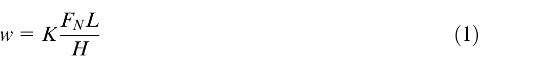
A large number of models have been developed for the description of friction and wear phenomena based on either empirical studies or basic principles of contact mechanics. 10 The Archard wear model 11 is the most commonly applied wear model in commercial FE software for modeling of wear in manufacturing processes. The wear model states that the volume loss w (mm3) due to wear is governed by the product of the normal force FN (N) and the accumulated sliding length L (mm) and is inversely proportional to the surface hardness H (HRC). The wear coefficient K is determined by the material properties of the contact pair. The wear model is then given as
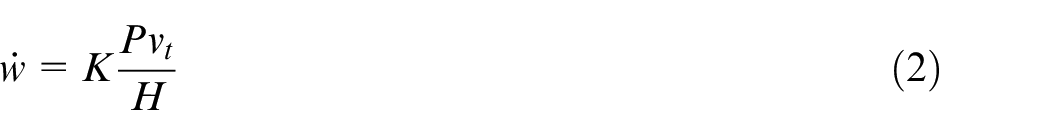
For adaption of the wear formula into FE calculations, the wear volume change per unit area
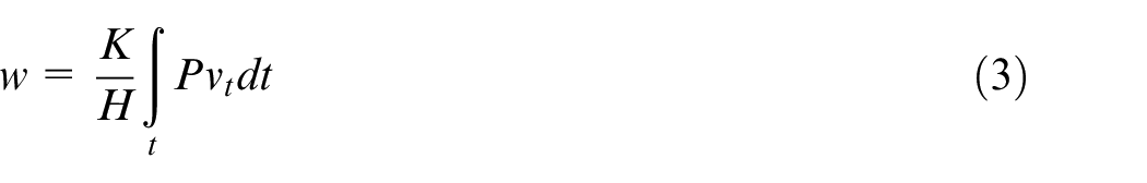
The total wear volume is obtained by integration of the wear volume rate over time
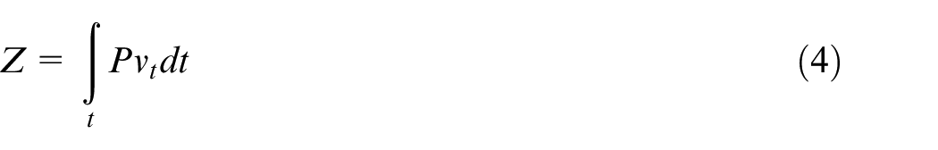
The integral in equation (3) introduces the wear work Z (MPa·mm), which allows for a qualitative evaluation of the wear severity independent of the material properties of the contact pairs, as the wear work is directly proportional to frictional energy dissipated in the contacting surfaces. 12 The wear work is thereby
Holm 13 and Rabinowicz 14 described wear models with structures similar to Archard’s wear model for describing atomic wear in electrical contacts and abrasive wear, respectively.
Experimental and numerical procedure
This study is an industrial case based on the production of an automotive component for exhaust gas recirculation (EGR). The component is made in a one-step stamping operation of a 1.5-mm-thick blank of EN 1.4301 stainless steel. The forming process is carried out with a manually operated hydraulic, single-action press with a draw cushion, where the forming die is lowered down over a stationary draw punch. The production rate of the component is approximately 150 parts per hour. The forming die has a stepped drawbead geometry around the perimeter of the die opening to control the flow of the sheet metal during the forming operation. The forming tool is shown in Figure 1. The final geometry of the drawbead was obtained through a trial and error procedure in the die tryout stage.
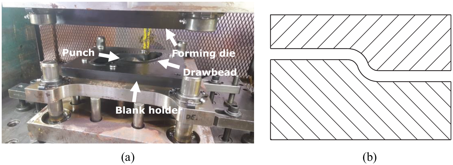
Overview of the forming tools by (a) identification of the punch, forming die, and the blank holder, where the stepped drawbead is visible, and (b) schematic cross section of the drawbead geometry around the perimeter of the die opening.
Scanning of blank holder and forming die
A three-dimensional (3D) scan of the forming die was made using an ATOS Triple Scan optical scanner. The optical scanner measures the geometry of the die by triangulation of a fringe pattern that is captured using a two-camera system. For measurement of the forming die, a series of 3 mm reference points were placed on the die surface outside the areas of interest. Since the forming die has a highly polished surface, a thin layer of titanium oxide was sprayed onto the die in order to minimize reflection and enhance the definition of the captured surface. Calibration of the optical system was done according to the recommended procedure from the manufacturer. This involved measurement of a calibration panel from varying distances, positions, and different orientations of the camera system. The measurements were carried out with a MV560 (560 × 420 × 420 mm3) lens setup at a measuring distance of approximately 830 mm in a temperature-controlled laboratory with air temperature of 20.5 °C ± 0.5 °C. Two separate series of scans were conducted for the blank holder and the die geometry, each consisting of 10–12 partial scans that were merged into one final model. Post processing of the obtained die geometry was done with the MeshLab software. Post processing of the scanned die geometry consisted of the removal of redundant scanned features and down sampling of the generated point cloud with a Poisson-disk algorithm in order to reduce the point cloud to approximately 40–50,000 data points. This was done in order to facilitate further processing of the scanned model, while still maintaining an accurate discretization of the die geometry.
FEM model
The scanned model was imported into LS-DYNA for FE analysis of the stamping process. For the FE analysis, the forming tools were modeled as elastic steel tools with a variable mesh size of 0.5–1 mm around the drawbead region, in order to adequately simulate the bending action introduced by the drawbeads. The geometry of the blank was modeled with a quadrilateral mesh with an initial mesh size of 2.5 mm with adaptive remeshing, with three levels of mesh refinement during simulation. The simulation was set up with a standard shell element formulation (Belytschko–Tsay formulation). Characterization of the strain hardening behavior of the sheet material was done with a plane strain compression test, where a Voce hardening curve of σf = 135 + (1785 − 135)(1 − e−2.5ε) (MPa) was determined for the material, where σf is the flow stress of the material and ε is the equivalent strain. The Coulomb friction model was adapted for the FE setup with a friction coefficient of μ = 0.1.
Results and discussion
Analysis of drawbead geometry
While several simplified guidelines exist for the design of drawbeads, 15 the actual drawbead design implemented in the stamping dies is highly dependent on the component geometry, the sheet thickness, and the experience of the die manufacturer. In the die tryout stage, the die manufacturer modifies the drawbead geometry by manual grinding in order to adjust the flow of the sheet material, while trying to avoid a drawbead geometry that introduces excessive thinning of the sheet material and forming defects such as cracks, wrinkles, and orange peeling. This trial and error approach results in a wide range of different drawbead geometries used in industrial forming dies, which are often prone to galling, since die features like the die shoulder and drawbeads are often subjected to high-localized normal pressures. 16 A general overview of the drawbead geometry of the forming die in this study is shown in Figure 2.
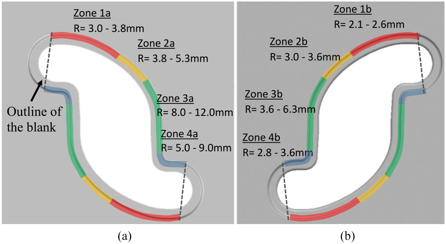
Overview of the rounding radii of the drawbead geometry of (a) the blank holder and (b) the forming die.
Four zones, grouped by the size of the rounding radii of the drawbead, are identified on the blank holder and the forming die in Figure 2. Zone 1 and zone 2 contain relatively small rounding radii, which result in heavy restraining of the material flow. Zone 3 and zone 4 have larger rounding radii, resulting in less restrictions of the material flow. The influence of the drawbead geometry on drawing behavior of the stamped component is illustrated in Figure 3 by comparing the outer contour of the flange to the initial blank contour. Figure 4, furthermore, shows the thickness distribution of the formed component with the initial drawbead geometry and the geometry obtained during the die tryouts.
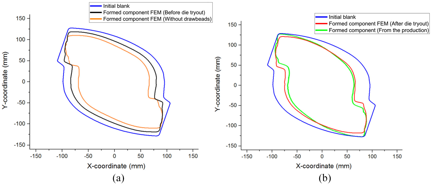
Initial blank and outer contour of component after stamping with (a) the initial drawbead geometry and stamping without drawbeads by simulations and (b) the final drawbead geometry by simulation and production.
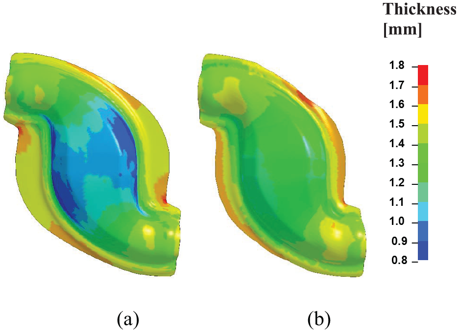
Thickness distribution of the formed component with (a) the initial drawbead geometry and (b) the final drawbead geometry.
Figure 3(a) shows the restraining action of the initial drawbeads geometry, where the rounding radii of the drawbead are equal to the thickness of the sheet material along the entire perimeter of the die cavity. The large restriction in the material flow, due to the small rounding radii of the drawbead, results in a large flange remaining after the forming operation and substantial thinning of the formed component (see Figure 4). The large restriction of the material flow greatly exceeds the 20%–30% formability guideline for the thickness reduction, commonly used for automotive components in stainless steel. The excessive thinning will possibly result in fracturing on the top part of the component, where the largest reduction in the thickness of the sheet metal takes place. Forming the same component without drawbeads, also shown in Figure 3(a), will conversely result in excessive draw-in of the flange material and will not induce sufficient work hardening of the sheet material. Forming the component without drawbeads will, furthermore, increase the risk of wrinkling due to insufficient stretching of the sheet material. Figure 4(b) shows that the drawbead geometry obtained in the die tryout introduces a variable restraining force along the perimeter of the sheet metal blank, seen in the variable sliding length of the sheet material. The variable draw-in of the sheet material ensures a uniform thickness of the formed component and that the component has a remaining flange that enables proper trimming of the formed component for the subsequent production steps. Figure 4, furthermore, shows that the drawing behavior of the sheet metal can be approximated well with numerical simulations with the implementation of the scanned forming die. Minor deviations between the numerical results and the formed component are found, most noticeably, at the upper end of zone 1 where the flow of the sheet material is completely restricted and in zone 4 where the flow of the sheet material is underestimated in the simulation. The variable forming conditions introduced by the drawbeads impose different tribological loads on the forming tools. For the evaluation of the severity of the forming process, a simulation of the distribution of the normal pressure and the wear work was made (see Figures 5 and 6).
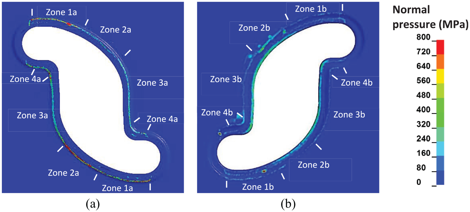
Simulated normal pressure in (a) the blank holder and (b) the forming die.
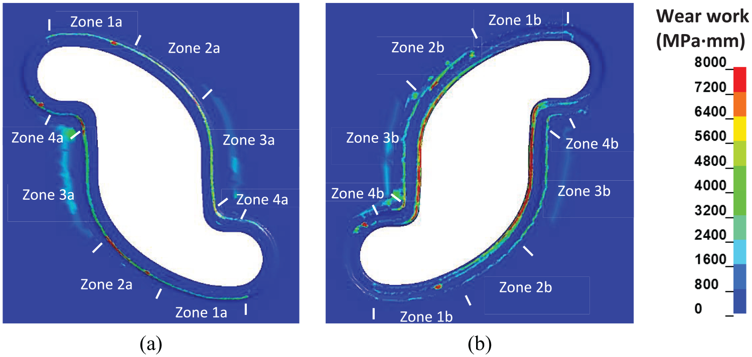
Simulated wear work in (a) the blank holder and (b) the forming die.
From the simulated pressure distribution in Figure 5, it is confirmed that the zones with smaller rounding radii of the drawbeads are exposed to higher normal pressures. From the wear work in Figure 6, it is similarly seen that the combination of high local normal pressures and moderately long sliding lengths (as observed in Figure 4) results in severe wear conditions in zone 2, with a wear work of more than 8000 MPa·mm. Another critical region, in terms of wear, is the die shoulder in zone 3, which is subjected to moderately high normal pressures combined with a very long sliding length at the center of the component. The planar contact between the die and the blank holder, in zone 3, is similarly exposed to increased wear work due to the longer sliding length of the sheet material.
Offline screening of suitable lubricants
Based on the analysis of the drawbead geometry and the resulting tribological loads the drawbead design introduces, a tool has been designed to experimentally replicate the drawbead conditions in zone 2, which exhibits the most severe tribological loads as seen in the simulated wear work. A schematic illustration of the tool design and the experimental testing parameters is shown in Figure 7. The drawbead test was conducted on the universal sheet tribotester (UST) developed at the Technical University of Denmark. 17 The UST enables simulative testing with process times that replicate the actual production speed of the production platform in order to maintain a similar temperature profile in the forming tools. The offline screening of alternative lubricants was made with an untreated Sleipner die material and with a Tenifer® quench polish quench (QPQ) surface treatment of the die material, respectively, to emulate the two versions of the forming die used for the production of the EGR component. The manufacturer specifies that a forming lubricant for the specified production platform should support a minimum of 200 strokes without deterioration of the surface quality of the formed component due to lubricant film breakdown.
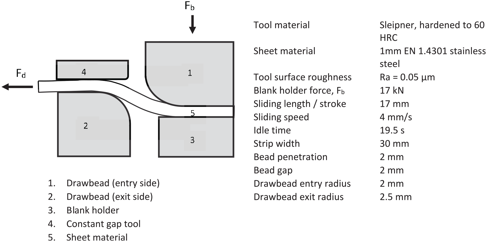
Overview of the tool design and experimental testing parameters.
The presented test setup was made with sheet material of 1 mm thickness. Scaling down the drawbead dimensions with the same factor as the sheet thickness allows to emulate comparable drawing characteristics in terms of surface strains, drawbead restraining force, and contact pressures in the tool/workpiece interface.15,18 The testing parameters were, furthermore, designed to emulate the actual production parameters of a manually operated press in terms of process times and the sliding speed of the forming tools. The measured drawing force during testing and the developed tool wear after 300 strokes are shown in Figures 8 –10 for the tested tribosystems.
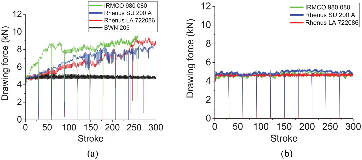
Measured drawing force during testing with Sleipner tool material (a) without any surface treatment and (b) with a Tenifer® QPQ surface treatment.
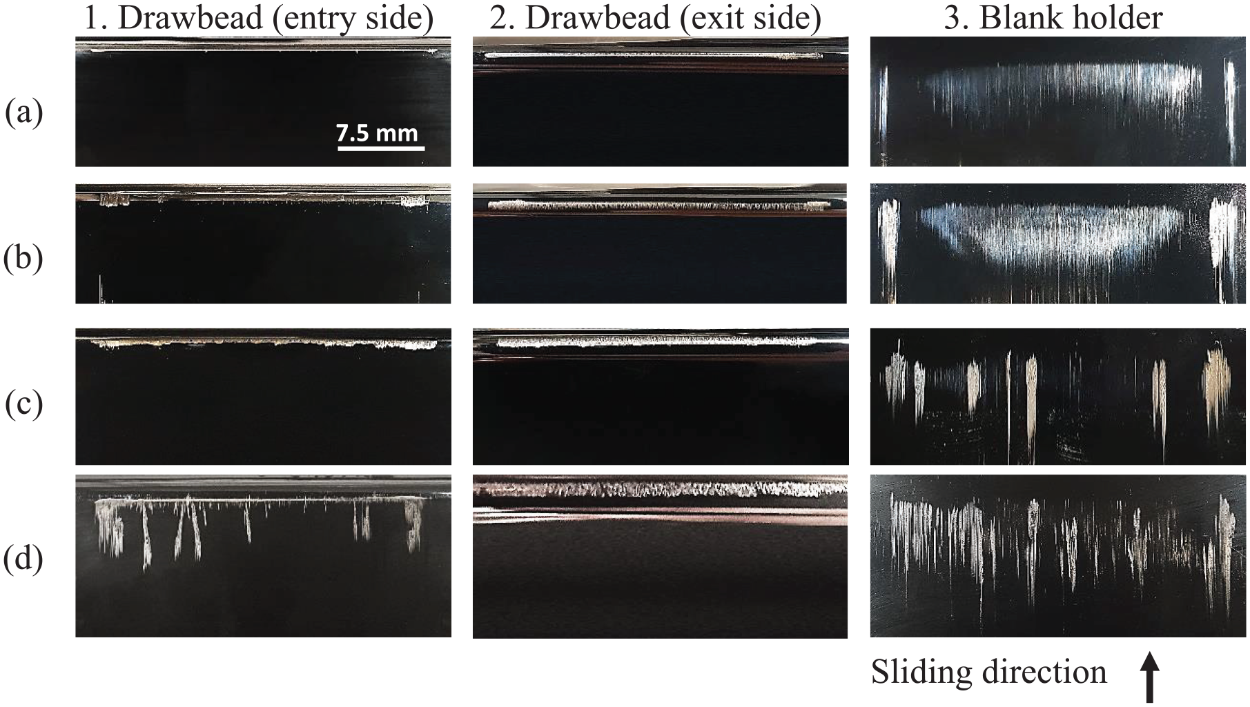
Tool surface, without surface treatment of the tools, after 300 strokes with the tested lubricants: (a) BWN 205, (b) Rhenus LA 72208, (c) Rhenus SU 200 A, and (d) IRMCO 980 080.
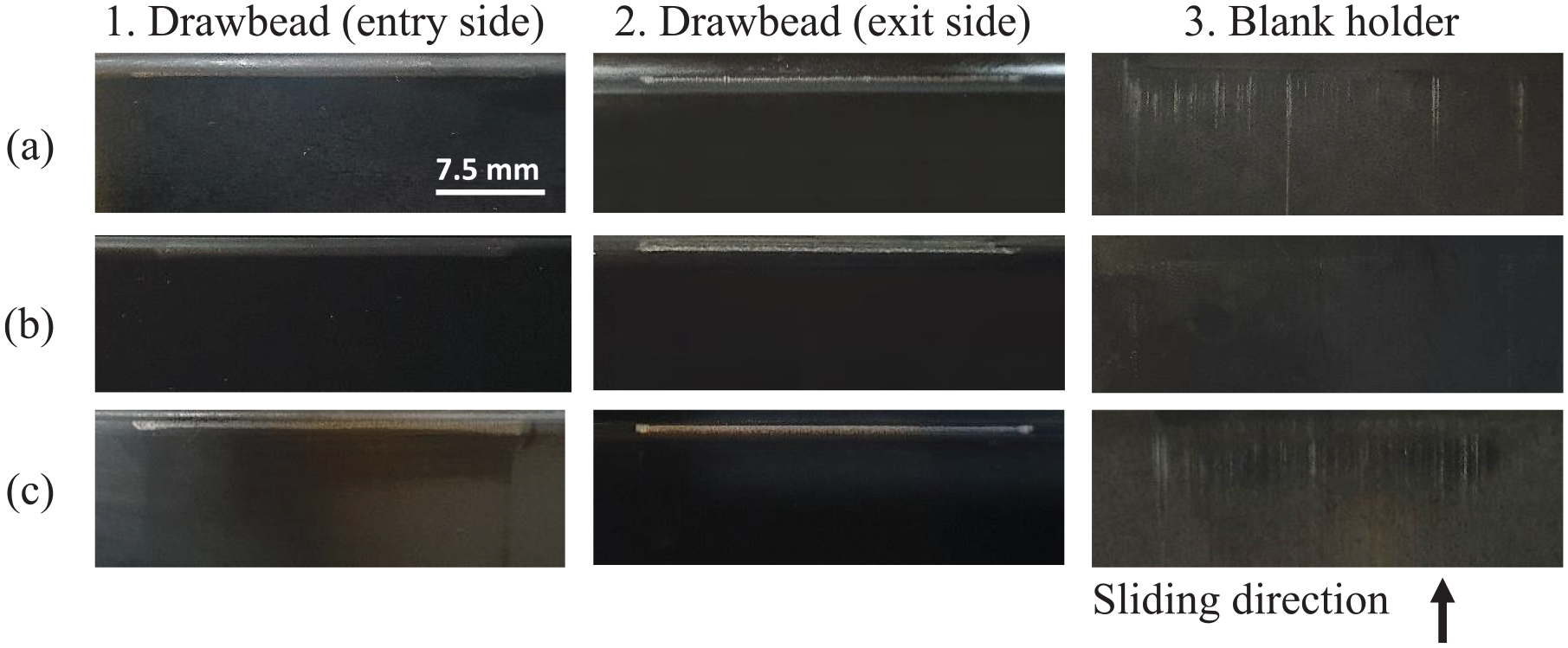
Tool surface, with a Tenifer® QPQ surface treatment, after 300 strokes with the tested lubricants: (a) Rhenus LA 72208, (b) Rhenus SU 200 A, and (c) IRMCO 980 080.
From Figure 9, it is seen that the test series with the Rhenus LA 722086, Rhenus SU 200 A, and the IRMCO 980 080 lubricants experience a rampant development of the drawing force within the first 50 strokes. This corresponds well with the visible scoring of the tested sheet metal surface. Compared with the surface structure of the tool after 300 strokes (Figure 9), it is seen that a substantial amount of pickup of workpiece material has been accumulated on both the rounding of the drawbeads and the plane contact that emulates the contact in the blank holder region of the forming die. The BWN 205 lubricant, which is a highly chlorinated, heavy-duty deep drawing lubricant, has a stable drawing force during testing. The surface structure of the tools shows only minor signs of initial run-in wear without any friction junctions formed on the tool. None of the selected, environmentally friendly lubricants could, therefore, replace the BWN 205 when conducting the tests with uncoated tools. The selected lubricants were, however, found to exhibit a significantly improved tribological performance in the test series conducted with the Tenifer QPQ–treated tools. The test series conducted with the Tenifer QPQ surface treatment were found to exhibit stable drawing forces and smooth surface structure of the sheet material after testing, for all the tested lubricants. Evaluation of the tool surface indicates only minor signs of abrasive wear without any sign of pickup of sheet material on the tools. This is seen in Figure 10, where only minor scratches are found on the tool surface due to run-in wear of the iron nitride surface layer formed with the Tenifer QPQ surface treatment. The presented results indicate that certain, tribologically severe forming operations require a deeper refinement of the tribosystem in order to implement environmentally friendly, non-chlorinated lubricants. For the EGR component, the combined function of the Tenifer QPQ surface treatment and an alternative, environmentally friendly forming oil was found to exhibit sufficient tribological integrity to replace the heavy-duty, chlorine-based BWN 205 forming oil.
Conclusion
This study showcases a methodology on how critical die features in a forming die can be evaluated for the characterization of the wear behavior. An industrial tool for sheet metal forming has been 3D scanned and imported into an FE simulation software for analysis of drawing in, normal pressures, and die wear. The simulated drawing of the flange shows the influence of a stepped drawbead by comparing (1) the absence of the drawbead, (2) a drawbead with a constant radius equal to the sheet thickness, and (3) an optimized drawbead geometry. The simulation also identifies critical zones along the die shoulder and the stepped drawbead in terms of wear severity. These zones were emulated by simulative testing for offline evaluation of different tribosystems. For the specific production platform, it was found that only the hazardous, chlorinated lubricant could facilitate a stable production with an uncoated tool steel. The tribological function of the Tenifer QPQ surface treatment combined with different forming oils could form the basis for an alternative, environmentally friendly tribosystem for replacement of the hazardous, chlorinated lubricant currently used in production. For new tool designs, the presented method can be used to optimize the die geometry and reduce the time and costs related to the die tryout process. The optimization will encompass an evaluation of the tool life and the drawing behavior of the component.
Footnotes
Declaration of conflicting interests
The author(s) declared no potential conflicts of interest with respect to the research, authorship, and/or publication of this article.
Funding
The author(s) received no financial support for the research, authorship, and/or publication of this article.