
Abstract
In this study, laser solid forming technology has been used to fabricate Rene 104 nickel-based superalloy parts, and severe crack problems were found during the laser solid forming process. To solve the crack problems, the effects of preheating and cooling on the microstructure and crack defects of the laser solid forming Rene 104 superalloy were experimentally investigated. The experimental results demonstrated that crack intensity in parts obtained using laser solid forming decreased with the increase in the preheating temperature. However, when the cooling process was not controlled, the parts obtained using laser solid forming would still exhibit severe crack problems even if the preheating temperature was increased to 750 °C. Therefore, instead of natural cooling, a slow cooling strategy was used after the laser solid forming process in the experiments. It was proved that decreasing the cooling rate of the substrate also helped in eliminating the cracks. Using the slow cooling strategy, crack-free Rene 104 superalloy parts could be fabricated at a relatively low preheating temperature. Moreover, it was found that the multiple growth direction of columnar dendrites under high preheating temperature restricted the propagation of cracks. The microsegregation of Al and Ti in the interdendritic regions decreased when the slow cooling strategy was used, leading to improvements in ductility. Aside from the evolution of the microstructure, the relief of thermal stress during the slow cooling process was another important reason for eliminating the cracks.
Introduction
Rene 104, a third-generation powder metallurgy nickel-based superalloy, has been widely used for manufacturing aeronautical and naval components due to its good balance between creep resistance, damage tolerance, and tensile properties at elevated temperatures. However, traditional powder metallurgy (PM) forming is a complicated, time-consuming process that has a high production cost. Moreover, it is difficult to fabricate components with complex shapes using the PM processing method.1,2 Due to the high concentration of refractory elements and the inherent interaction capabilities among the complex precipitation strengthening phases in the Rene 104 superalloy, the machining of Rene 104 superalloy is difficult.3,4 Therefore, the forming and machining of Rene 104 superalloy have presented huge challenges because of the increased use of complex-shaped components in the aeronautical and naval industries.
Laser solid forming (LSF), also known as direct laser deposition (DLD) or laser engineered net shaping (LENS), is a typical additive manufacturing technology that combines the advantages of rapid prototyping and laser cladding. Compared to the traditional processing method, LSF can achieve near net shape forming of components without die. Moreover, the production cost and fabrication time are significantly reduced because of the simplified forming and machining processes.5–10 Given the notable improvement in production flexibility, LSF is a promising method for manufacturing Rene 104 superalloy components.
However, for Ni-based superalloys with high Al and Ti content (generally Al + Ti > 6 wt.%), hot cracks are formed easily during high-energy beam processing.11,12 The simulation results have proved that the central area in laser spot can be heated to an extreme high temperature in a very short time, while there was a steep temperature gradient in the LSF part and the other areas were in a rapid cooling process. 13 During the rapid heating and cooling processes of LSF, it has been found that cracks are mostly induced due to the liquation of the heat-affected zone (HAZ) and thermal stress, which are caused by the inhomogeneous thermal field and steep thermal gradient in the deposit. Some attempts have been made to eliminate the cracks. Some authors have found that the heat input during the LSF process was closely related to the crack defects; thus, by controlling the LSF process parameters, the crack defects in the superalloy could be inhibited.14–17 Many parameter optimization studies have been conducted. The effects of the processing parameters (such as laser power, scanning speed, and powder feeding rate) on the quality of the deposit were analyzed.18–20 However, the influence rule of process parameters varies with different kinds of superalloys; thus, it is difficult to deduce the best processing conditions based on previous experimental results. Moreover, Yang et al. 2 have proved that dense Rene 104 samples without cracks cannot be fabricated only by optimizing the process parameters. Aside from controlling the process parameters, post-treating is also used to eliminate cracks. Zhao et al. 21 investigated the crack behavior while manufacturing Rene 88DT using LSF, where hot isostatic pressing (HIP) treatment was used to heal the cracks after the LSF process. Although the HIP treatment can effectively heal the cracks in LSF superalloy parts, the high cost of the HIP treatment equipment makes it difficult to promote this method. Preheating the substrate is another useful way to inhibit crack defects during LSF. Many studies have been carried out to explore the relationship between the preheating temperature and the crack defects in parts obtained using LSF. Experimental results revealed that crack-free deposits can be obtained at an extremely high preheating temperature, which exceeded 1000 °C for superalloys in general. The decrease in temperature gradient and thermal stress was the main mechanism for eliminating cracks when preheating was used.22–24 The most suitable preheating temperature is different for different types of superalloys. Moreover, the required preheating temperature for a certain superalloy is also not constant, and it changes with the processing conditions. 25 Because high preheating temperatures require specialized equipment and take a great deal of energy, it is meaningful to lower the preheating temperature by optimizing the processing conditions. Because of the high preheating temperature, the temperature of parts obtained using LSF is still quite high after the LSF process finishes. In most cases, natural cooling conditions (direct cooling in air or shielding gas) are used to lower the temperature of the parts. During high-energy beam processing, the cooling process always has an effect on the microstructure and defects in materials.26,27 Some authors have proved that finer microstructures and better mechanical properties (such as corrosion resistance and hardness) could be obtained under rapid cooling conditions.28–30 However, the extremely rapid cooling and solidification rates may also lead to large accumulation of residual stress and the nonequilibrium solidification process, both of which are not favorable for eliminating the cracks in superalloy parts obtained using LSF.31,32 In addition, Mitchell and colleagues33,34 demonstrated that during the heat treatment of nickel-based superalloys, the cooling rate had a significant influence on the morphology of γ′ precipitation, which would also affect the formation of cracks in the liquation of the HAZ. Furthermore, the temperature gradient, which plays an important role in eliminating the crack defects in the parts obtained using LSF, may also be closely related to the cooling process. However, there are few studies concerning the effects of the preheating and cooling processes on the microstructure and defects of the LSF Rene 104 superalloy to date. The evolutions of microstructure and crack defects in Rene 104 superalloy parts are still unclear when using different cooling processes during the LSF process. More research efforts are required.
In this study, the crack behavior of the Rene 104 superalloy during the LSF process was described and the main reasons for the formation of cracks were analyzed. To solve the crack problems, by controlling the preheating temperature and cooling rate of the substrate, different preheating and cooling processes were used during the LSF process. The effects of the preheating and cooling processes on the microstructure and crack defects were experimentally investigated in detail. The microstructure evolution and crack suppression mechanism were also discussed. A method for inhibiting the crack defects of the LSF Rene 104 superalloy by controlling the preheating and cooling process was provided.
Materials and methods
All the LSF experiments involved in this study were performed on a self-developed LSF equipment, which consisted of a SPI 400W continuous wave laser, a computer numerical control (CNC) working table, and a coaxial powder feeding system. Pure argon was used as shielding and powder carrying gas, a heating board was used to heat the substrate, and an infrared thermometer was used to monitor the temperature of the substrate in real-time. The schematic diagram of the LSF equipment is presented in Figure 1.
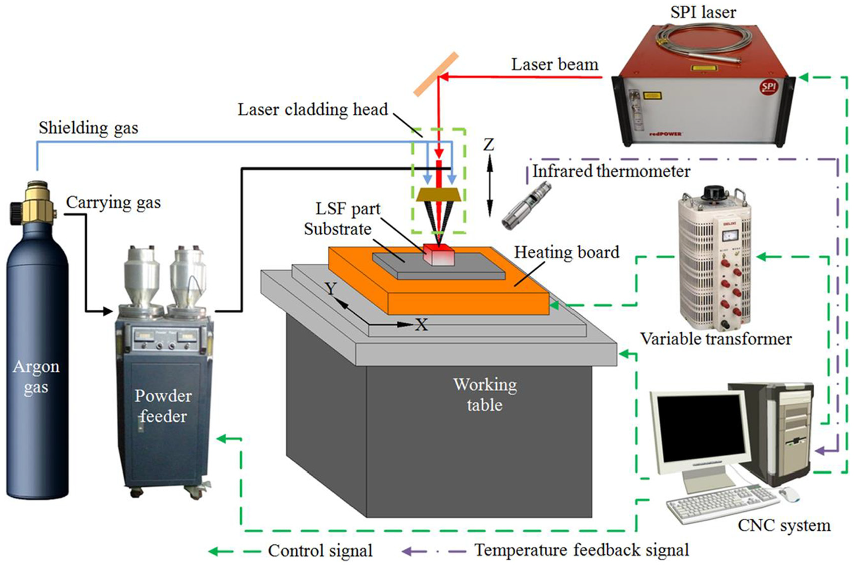
Schematic diagram of the LSF equipment.
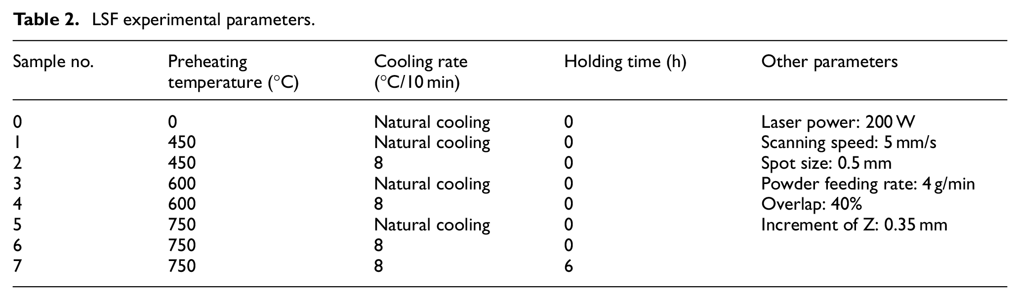
To achieve different substrate cooling rates, the heating board was driven by a variable transformer. By adjusting the voltage of the variable transformer, the heat dissipated by the heating board was controlled and different substrate cooling rates were obtained. Rene 104 spherical powders with particle size in the 45–100 μm range were laser-deposited on a 150 mm × 150 mm × 8 mm stainless steel substrate. The chemical composition of Rene 104 superalloy is presented in Table 1. The substrate surface was ground using SiC abrasive paper and cleaned using absolute ethanol in an ultrasonic bath before being laser-deposited. To find the most suitable preheating and cooling processes, a series of experiments were conducted. Before the LSF process, the substrate was preheated, and three different preheating temperatures were used in the experiments. When the LSF process finished, the cooling rate of the substrate was controlled, and three different cooling profiles were applied. The detailed experimental parameters are listed in Table 2. Figure 2 shows the laser scanning strategy and different cooling processes used in the experiments. The dimension of the bulk sample fabricated using LSF was approximately 35 mm × 15 mm × 2–5 mm. The dimension along the Z-direction varied with different process parameters.
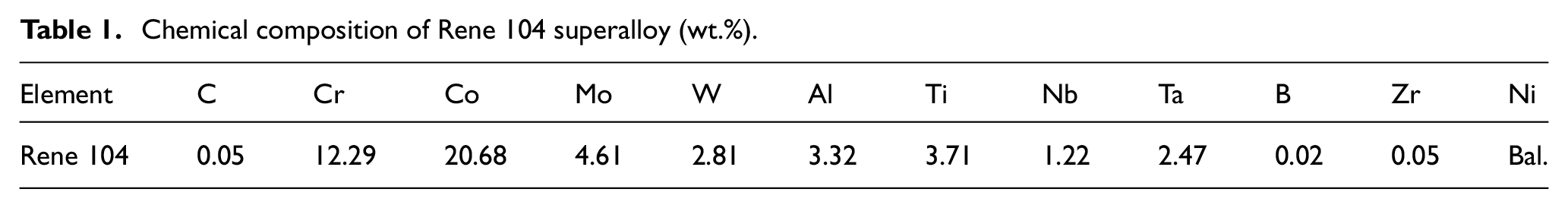
Chemical composition of Rene 104 superalloy (wt.%).
LSF experimental parameters.
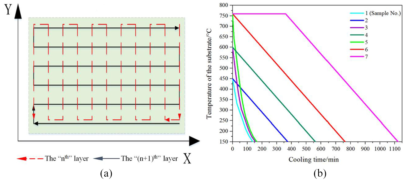
(a) Laser scanning strategy and (b) different cooling processes used in the experiments.
To observe the microstructure of the cross sections, the samples were sectioned using the method of wire electrical discharge machining (WEDM). The cutting position of sample is shown in Figure 3(a). The cross sections used for microstructure observation in this article were paralleled to the deposition direction. When observing the microstructure of the cross section, the central area of the cross section was chosen. The metallographic specimens of the cross sections were prepared using standard metallographic techniques, and the etchant used for revealing the microstructure consisted of 50 mL H2O, 50 mL HCl, and 10 g CuSO4. Thereafter, the microstructure of the cross section was investigated using an FEI Quanta 250 environmental scanning electron microscope (SEM) and an Olympus BX51M optical microscope (OM). Energy-dispersive X-ray spectrometer (EDS) was utilized to analyze the chemical composition of the samples. The volumes and cross-sectional areas of the deposited samples varied with different process parameters. Thus, crack intensity, assessed via the crack numbers per unit of cross-sectional area, was used to describe the crack behavior in the LSF sample. Crack intensity Ci was defined as
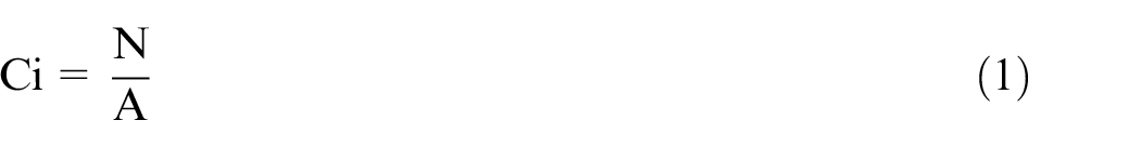
where N is the number of cracks and A is the cross-sectional area (mm2).
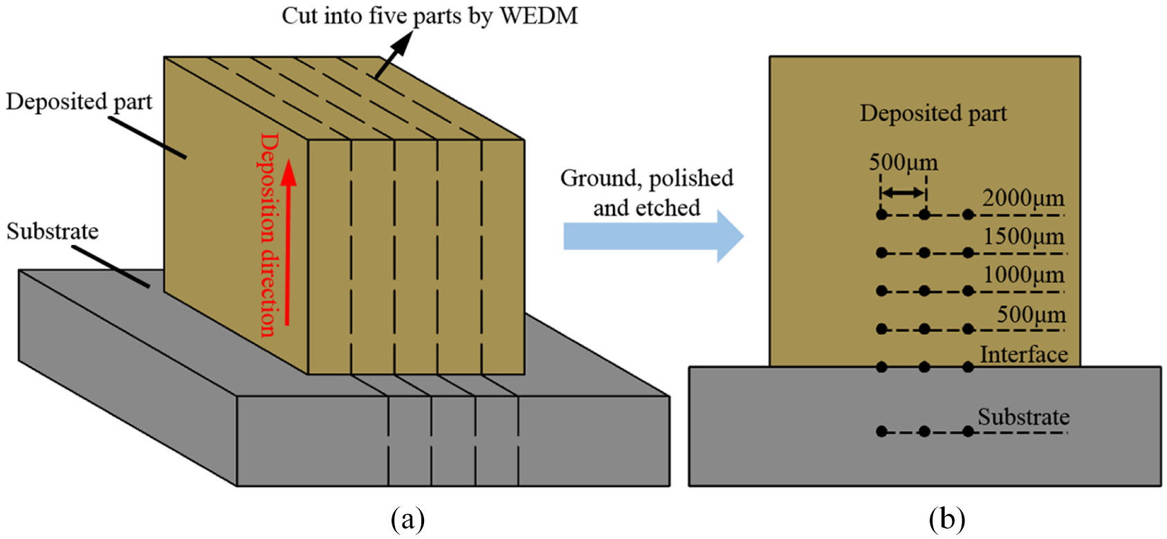
(a) The cutting position of sample and (b) the locations of hardness tests.
Moreover, to reveal the effect of preheating and controlled cooling on the mechanical properties, a comparison study of density and microhardness was made. When measuring the density of the sample, first, a 30 mm × 10 mm × 1 mm cuboid was cut from the sample by WEDM. Then, the cuboid was weighed by an electronic scale (Zhuojing, BSM-220.4) and the density of sample was the mass of cuboid divided by its volume. The black dots in Figure 3(b) represent the locations of hardness tests. The microhardness of the sample was measured using a Vickers microhardness tester (FUTURE-TECH, FM-800) using a 500 g load for a dwell time of 10 s. The final hardness value was calculated by averaging data from three indentations at the same height but with an interval of 500 μm in the horizontal direction.
Results and discussion
Crack behavior and mechanism of the LSF Rene 104 superalloy
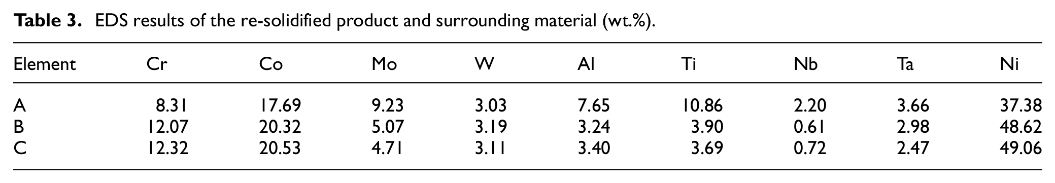
Figure 4 shows the microstructure of the LSF Rene 104 superalloy sample obtained without preheating. As can be seen from Figure 4(b)–(d), cracks mainly have two characteristics: (1) cracks initiate and propagate along the interdendritic regions or grain boundaries and (2) there are a lot of re-solidified products in the wide cracks. To determine the crack mechanism, the re-solidified product (marked A) and surrounding material (marked B and C) were analyzed using EDS. As shown in Table 3, the contents of Al, Ti, and Ta in the re-solidified product were evidently higher than those in the surrounding material. As Al, Ti, and Ta are the main elements of γ′ phase, it can be deduced that the re-solidified product was likely to be the re-solidified (γ + γ′) eutectics. 21 In order to analyze the phase transition process, a nonequilibrium phase diagram was used, and the phase diagram was referred to the study results by Yang et al. 2 As the phase transformation behaviors in the Ni–Al or Ni–Ti systems are similar, a Ni–Al binary phase diagram was used to replace the Ni–Al–Ti ternary phase diagram (Figure 5). For Rene 104 superalloy, the chemical composition was close to point A in the phase diagram.

Microstructure of the LSF Rene 104 superalloy sample obtained without preheating: (a) low magnification (OM image), (b) crack along the grain boundary (the white arrow represents the direction of the grain boundary), (c) highly magnified SEM image of the crack in (a), and (d) the initiation of cracks.
EDS results of the re-solidified product and surrounding material (wt.%).
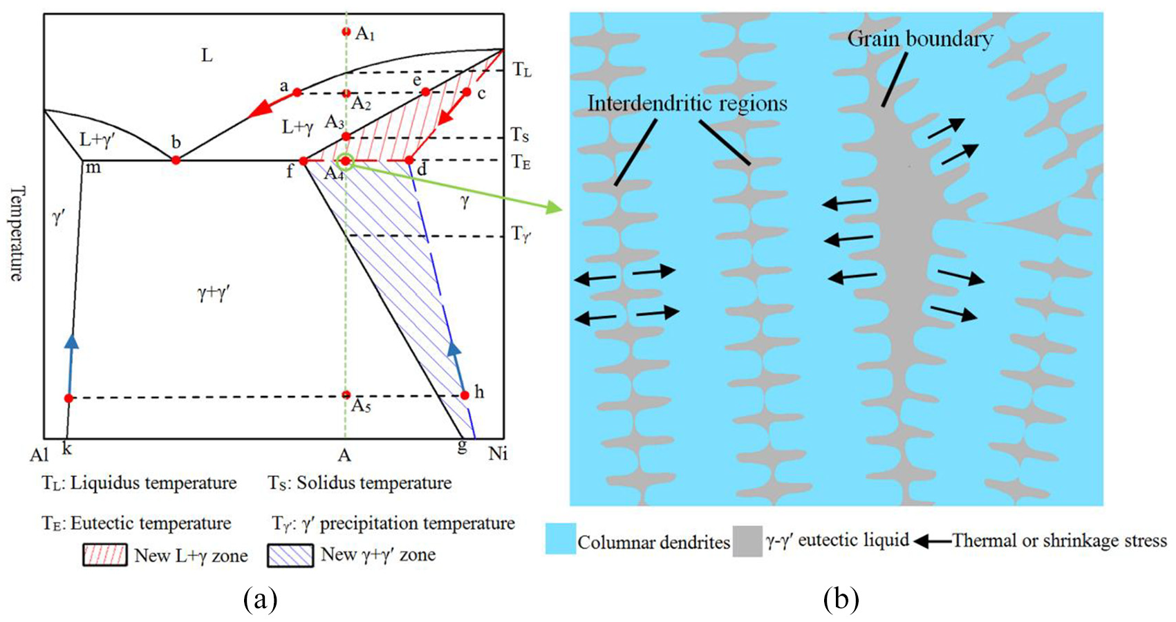
(a) Ni–Al binary phase diagram and (b) schematic diagram of the microstructure at eutectic temperature in the rapid cooling or reheating process.
During the LSF process, because of the repeated scanning strategy of the laser beam, the previous deposit areas would be repeatedly reheated and remelted. Any point in the LSF part would experience a series of temperature cycles, and the peak temperature of the temperature cycle decreased with the increasing distance between the point and the laser spot. Due to the rapid heating and cooling characteristics of LSF, there was a big temperature difference around the laser spot, which led to non-uniform deformation and large thermal stress.
When the temperature of the previous deposit areas exceeded the solidus temperature (TS), the previous deposit area would be fully or partly remelted. During the cooling process from point A1 or A2 to the eutectic point (A3), based on the phase diagram, it can be found that there would be no γ′ phase precipitating under slow cooling rate until the temperature decreased to the γ′ precipitation temperature (Tγ′). However, the rapid cooling rate of the LSF part led to the nonequilibrium solidification process. During the rapid cooling process, there was not enough time for Al element to diffuse in the γ matrix, which led to a higher Al content in the liquid. Without considering the uneven diffusion of Al element in the liquid, in the phase diagram the solid component changed following the line cd rather than line ef while the liquid component changed following the line ab. When the temperature decreased to the eutectic temperature, according to the lever rule, there would be still some liquid in the final solidification zones such as interdendritic regions and grain boundaries. The liquid component at eutectic temperature was close to the eutectic point b, and an enrichment of Al element would be found in the interdendritic regions or grain boundaries. There was a high possibility for the eutectic reaction to occur and produce γ–γ′ eutectics along these regions. When the thermal and shrinkage stresses overcome the low ductility of the material, the liquid film in the interdendritic regions or grain boundaries would be torn, causing cracks along these regions. Moreover, as the final solidification zones, it was difficult for these cracks to be backfilled from other liquid areas.
When the previous deposit area was reheated to the temperature between the eutectic point (TE) and the solidus point (TS), the γ′ phase which had already precipitated would dissolve into the γ matrix again (point A5 to point A3 in the phase diagram). If the reheating process was slow, the γ phase component would change following the line gf in the phase diagram. When the temperature reached the eutectic point, there would be no γ′ phase in the LSF part and it was impossible to produce (γ + γ′) eutectics.
However, because of the rapid heating rate of the LSF process, the γ′ phase would not have sufficient time to dissolve completely into the γ matrix, and the γ phase component actually changed following the blue line hd in the phase diagram. Thus, in this situation, there were still some γ′ phases remaining in the LSF part when the part was reheated to the eutectic temperature. The remaining γ′ phase would react with the γ matrix to produce a low-melting point eutectic liquid film at eutectic temperature, and the low-melting point eutectic liquid film would be more likely to form in the areas, such as grain boundaries and interdendritic regions, where there was an enrichment of Ti and Al. The low-melting point eutectic film weakened the grain boundary cohesion and led to a decrease in the ductility of the LSF part. Therefore, when the thermal stress exceeded the critical tensile stress, the liquation film would be undrawn and microcracks were formed.
Furthermore, because the heat dissipation direction during the solidification of the molten pool was approximately perpendicular to the surface of the substrate or pre-deposited layers, the microstructure of the LSF Rene 104 superalloy presented a columnar dendrite array growth pattern, which was epitaxially grown from the substrate. The crystallographic orientation of the columnar dendrite in different layers was similar. Therefore, because of the low ductile (γ + γ′) eutectics in the interdendritic regions, the crack might propagate along the interdendritic regions and traverse several layers to form a long crack.
It can be concluded that the microsegregation and large thermal stress caused by the repeated rapid heating and cooling processes seemed to be the main reasons for cracks. Thus, if the heating and cooling processes can slow down and be close to the equilibrium process, many cracks in the LSF parts can be eliminated.
Effect of preheating and cooling processes
The heights of the samples obtained under different conditions are presented in Figure 6. In the LSF experiment, the layer thickness has a close relationship with many parameters such as laser power, scan speed, and powder feeding rate. However, in this article, the preheating and cooling conditions were the only changing factors, while the other parameters affecting the layer thickness were the same in every experiment. It was found that the height of the samples was mainly determined by the preheating temperature. The height of the samples increased with the preheating temperature. Thus, increasing the preheating temperature could improve the manufacturing efficiency and it was unfair to evaluate the crack behavior by the total number of cracks. Instead of the total number of cracks, crack intensity was used to evaluate the crack behavior in the LSF samples. In this article, the crack intensity is a statistical average result of four cross sections in the LSF samples. The OM images of the transverse sections obtained for different preheating temperatures under natural cooling condition are presented in Figure 7. In addition, Figure 8 shows the statistical results for crack intensity in those samples. The experimental results demonstrated that the cracks in different LSF deposits exhibited different characteristics. It was found that the samples obtained without preheating presented the longest and widest crack. The percentage and crack intensity of the long crack (length >300 μm) were the highest in the samples obtained without preheating. When the preheating temperature was 450 °C, it was considered that the thermal stress was reduced and the reduced thermal stress led to the transformation of the cracks. The percentage and intensity of the long cracks (length >300 μm) decreased to some extent when the preheating treatment was applied. Although the long cracks were partially inhibited, compared to the sample obtained without preheating, the crack intensity of the small cracks (length <300 μm) increased in the sample obtained at a preheating temperature of 450 °C. It was inferred that even though the thermal stress was reduced by preheating, the reduced thermal stress in the sample was still large enough to cause small cracks in certain areas of the sample, which caused the long crack to transfer to small cracks and increased the crack intensity of the small cracks. Moreover, the intensity of crack (for both the long and short cracks) decreased with the increase in the preheating temperature. Nevertheless, the effect of the preheating temperature on the crack defects was more obvious for eliminating small cracks. Long cracks could still be easily found in the sample obtained at the preheating temperature of 750 °C. Moreover, as shown in Figure 9, at the edge of the LSF sample fabricated using a preheating temperature of 750 °C and natural cooling conditions, a crack was found between the sample and substrate, which indicated that the sample had the tendency to separate from the substrate because of the huge thermal stress. The increase of the preheating temperature can only mitigate and ameliorate the crack problem in the LSF Rene 104 superalloy when the cooling rate is not controlled.
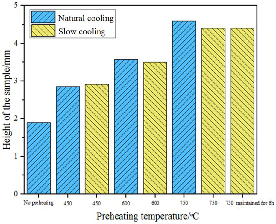
Heights of samples for different preheating and cooling conditions.
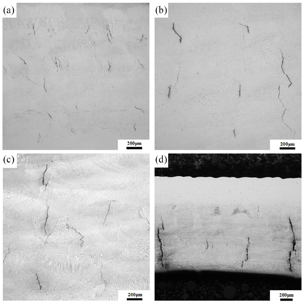
OM images of transverse sections obtained using different preheating temperatures under natural cooling conditions: (a) 450 °C, (b) 600 °C, (c) 750 °C, and (d) no preheating.
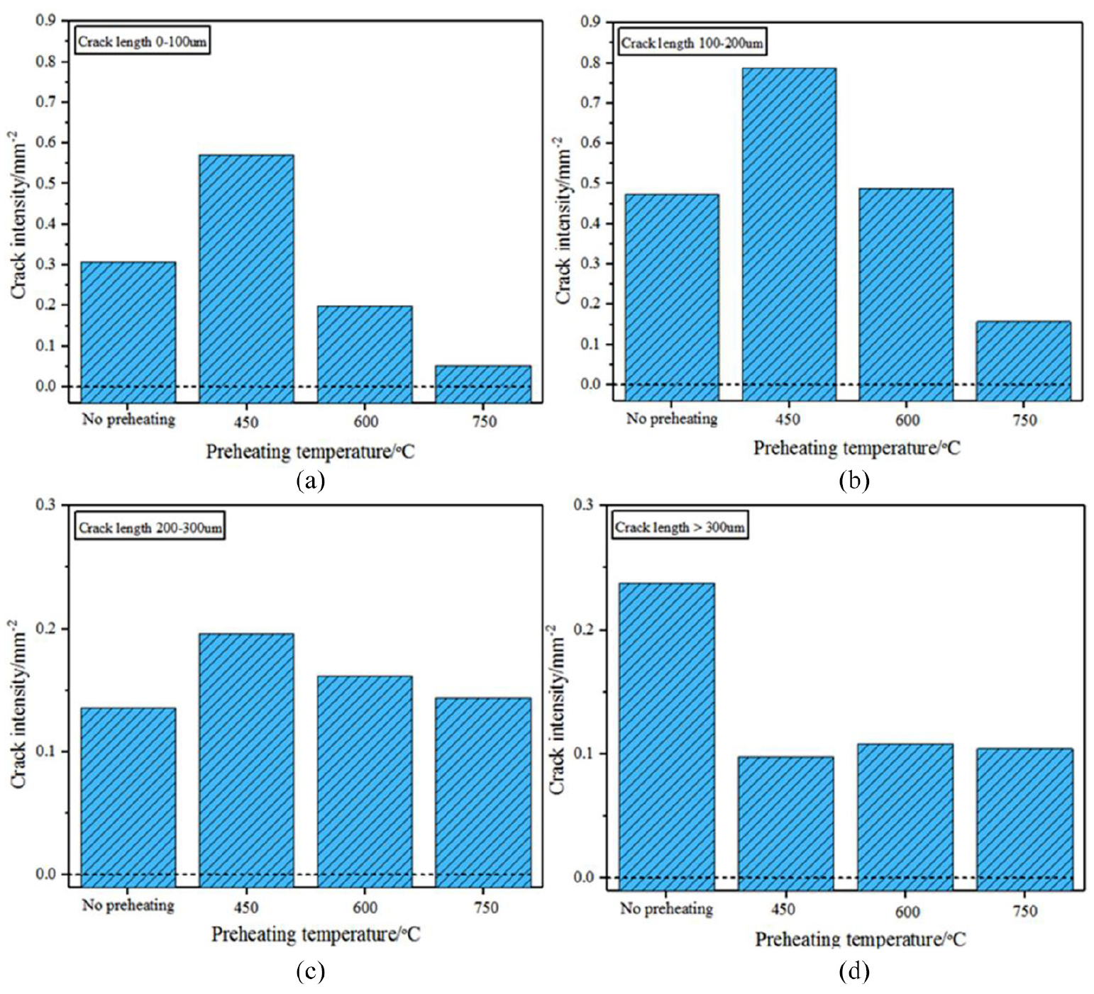
Crack intensity distributions in samples obtained using different preheating temperatures under natural cooling conditions: (a) crack length 0–100 μm, (b) crack length 100–200 μm, (c) crack length 200–300 μm, and (d) crack length >300 μm.
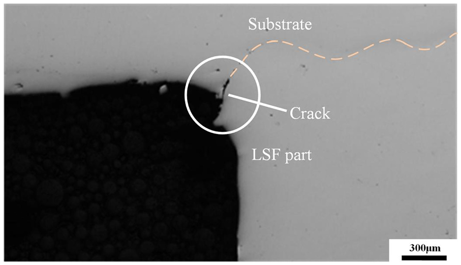
Crack between the substrate and part obtained using LSF (750 °C, natural cooling).
To release the thermal stress more thoroughly, a slow cooling strategy was used after the LSF process. Instead of cooling the samples directly using the shielding gas, the cooling rate of the substrate was controlled. The OM images of the transverse sections obtained when using different preheating temperatures under slow cooling conditions are presented in Figure 10. The statistical results for crack intensity of these samples are shown in Figure 11. According to the experimental results, it can be clearly seen that the crack problem was more severe under natural cooling conditions. It was obvious that the crack intensity decreased with the decrease in the cooling rate of the substrate for the cracks longer than 100 μm and it slightly increased for cracks shorter than 100 μm. The effect of slow cooling became more evident as the preheating temperature increased. When the preheating temperature was increased to 750 °C under slow cooling conditions, not only the intensity of the long crack significantly decreased but also the intensity of the small crack was very low. This phenomenon may be attributed to the larger difference in the cooling process at higher temperatures.
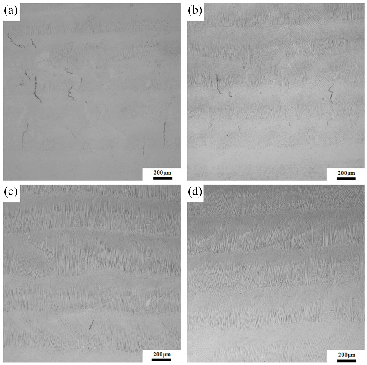
OM images of transverse sections obtained using different preheating temperatures under slow cooling conditions: (a) 450 °C, (b) 600 °C, (c) 750 °C, and (d) 750 °C maintained for 6 h.
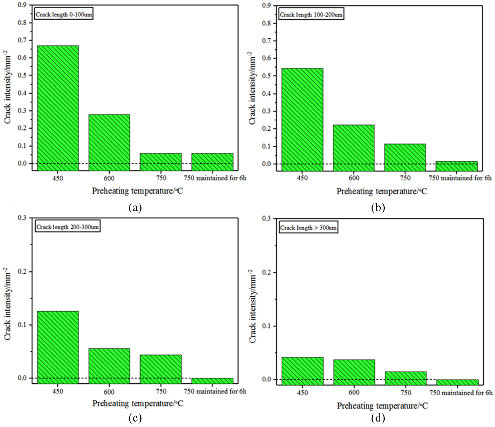
Crack intensity distributions in samples obtained using different preheating temperatures under slow cooling conditions: (a) crack length 0–100 μm, (b) crack length 100–200 μm, (c) crack length 200–300 μm, and (d) crack length >300 μm.
To solve the crack problem, an attempt to further decrease the cooling rate was made when fabricating Sample 7. Instead of cooling it down immediately after the LSF process, the temperature of the substrate was maintained for a period of time before cooling. The experimental results showed that by maintaining the temperature of the substrate, cracks started to become invisible at 75× magnification. There were hardly any long cracks (>100 μm) in the deposit, which further revealed the close relationship between the cooling rate and the occurrence of cracks, implying that decreasing the cooling rate could help eliminate the cracks. Furthermore, the small cracks discovered in Sample 7 were mainly distributed at the top of the sample, where the cooling rate was the highest. The cracks at the top could be easily removed by subsequent processing, and the required machining allowance was small. Compared with the preheating temperature used in previous studies (>1000 °C in general), the preheating temperature used to fabricate Sample 7 (750 °C) was low. Thus, it can be concluded that by controlling the cooling process, Rene 104 superalloy parts free of cracks can be fabricated at a relatively low preheating temperature. Moreover, the cooling strategy used for Sample 7 could be a suitable cooling strategy for fabricating LSF Rene 104 superalloy parts.
In addition, to reveal the effect of preheating and controlled cooling on the mechanical properties, the density and microhardness of Sample 0, Sample 5, and Sample 7 were measured and the experiment results are presented in Figure 12. The experimental result has demonstrated that both the high preheating temperature and the slow cooling strategy increased the density of samples and this phenomenon may be attributed to the decrease of cracks in the samples. As for the microhardness, it was believed that the microhardness of samples had a close relationship with the density and microstructure. The increase of density and the refinement of microstructure would improve the microhardness. At the interface and at the height of 500 μm, the microhardness of the deposited part was obviously influenced by the substrate. When the height is larger than 500 μm, it can be found that the sample obtained with the high preheating temperature and natural cooling condition (Sample 5) had nearly the same microhardness with the sample obtained with no preheating (Sample 0). When only the preheating method was used, the improvement of density was limited and the coarsening of microstructure caused by the high preheating temperature led to a decrease in microhardness. Thus, there is little difference in microhardness between Sample 5 and Sample 0. Compared to Sample 5, Sample 7, which was obtained with the high preheating temperature and slow cooling condition, had the highest density and lowest crack intensity. Although the coarsening of microstructure also decreased the microhardness of Sample 7, the significant increase of density still ensured that Sample 7 had the highest hardness.
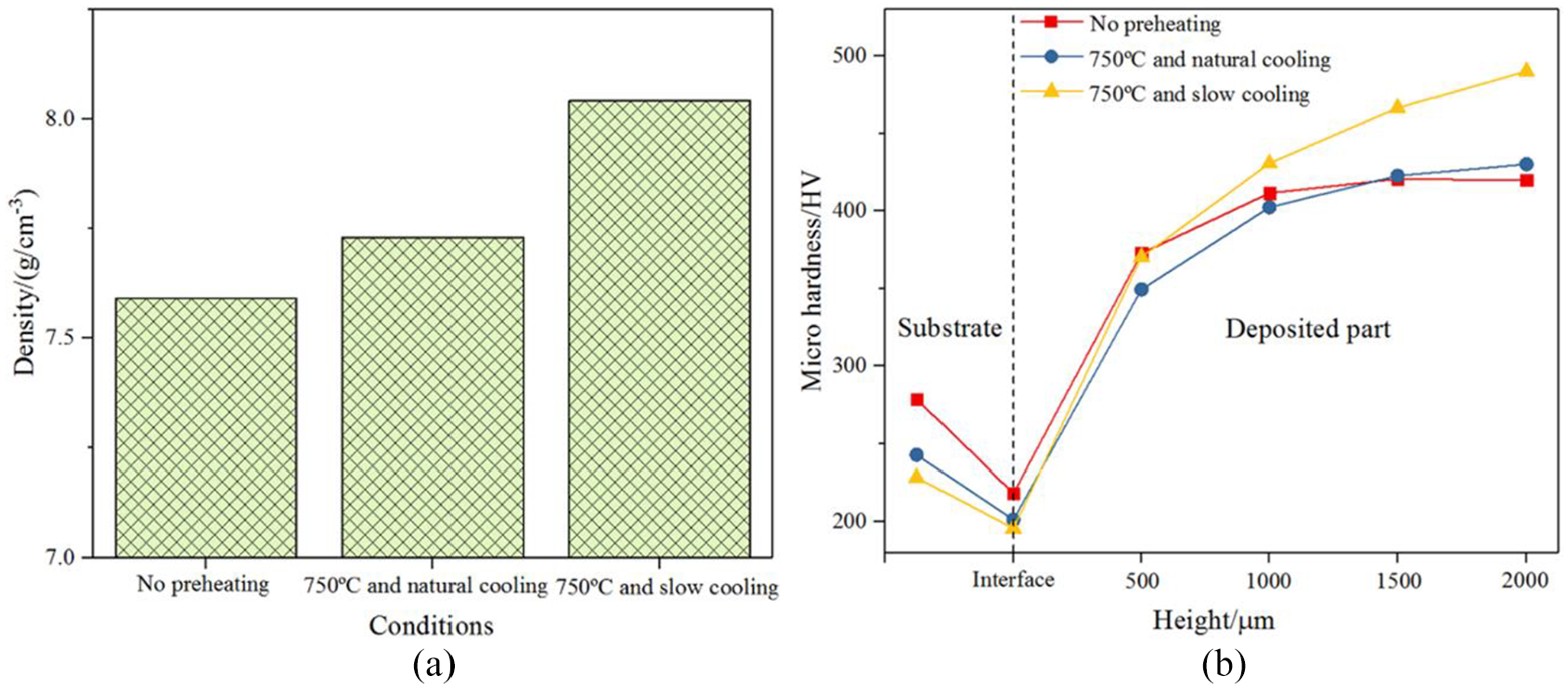
Comparison of density and microhardness of samples fabricated under different conditions: (a) density and (b) microhardness.
Microstructure evolution and crack suppression mechanism
By controlling the preheating and cooling processes, the microstructure of the LSF Rene 104 superalloy had been notably changed. The microstructures of the samples fabricated under different conditions are compared in Figure 13. As can be seen from Figure 13(a), for the sample obtained without preheating, the microstructure mainly consists of columnar dendrites with the growth direction approximately parallel to the deposition direction. However, in the preheated sample in Figure 13(b), the growth direction of columnar dendrites seems to be more irregular and the volume fraction of the columnar dendrites with the growth direction nearly perpendicular to present cross section is significantly higher compared to the no preheating sample. This phenomenon may be attributed to the chaotic heat dissipation direction and solidification sequence caused by the reduction of temperature gradient in deposition direction due to the high preheating temperature.
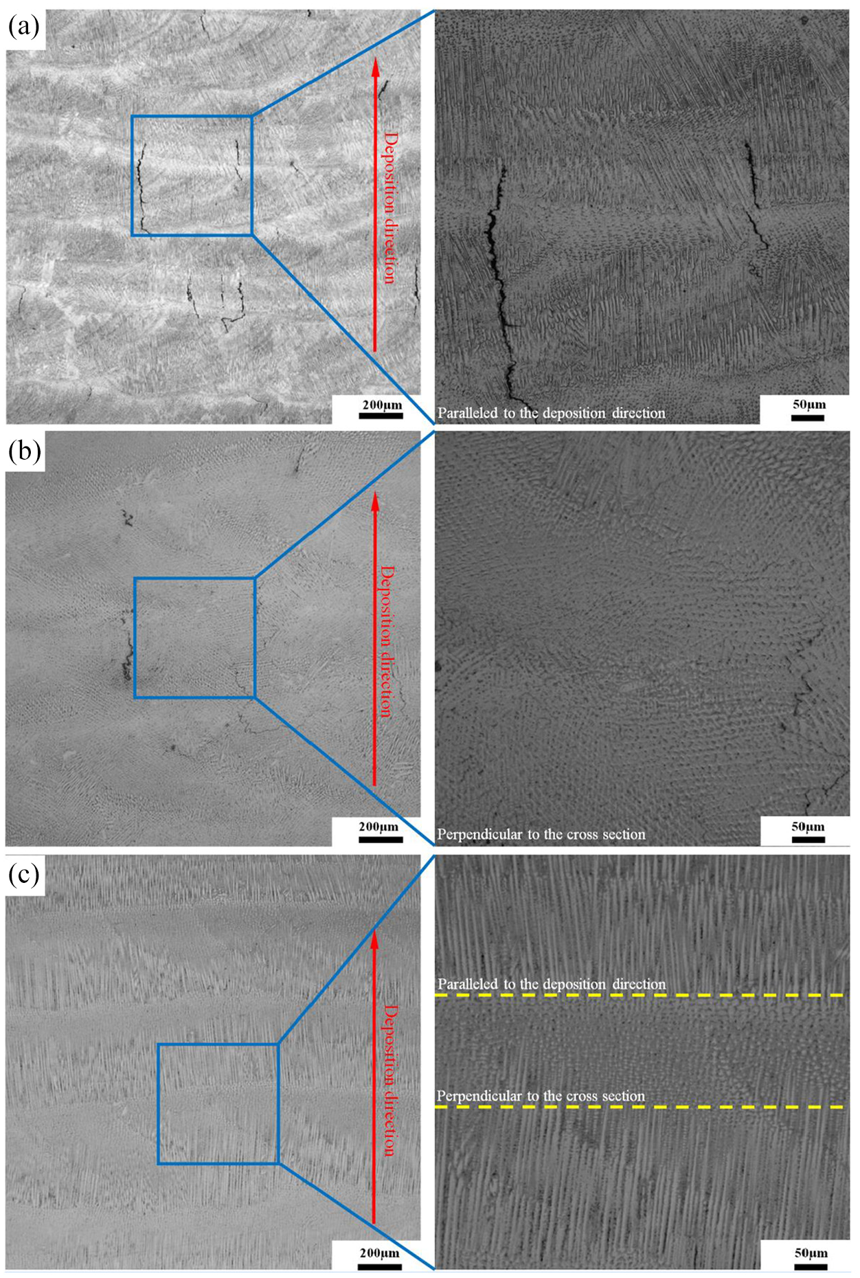
Comparison of microstructures of samples fabricated under different conditions: (a) no preheating, (b) 750 °C and natural cooling, and (c) 750 °C and slow cooling.
Moreover, as shown in Figure 13(c), a clear layered structure formed when the slow cooling strategy was used. Columnar dendrites with different growth directions distribute alternately in the slow cooling sample. For the same preheating temperature, when the slow cooling strategy was used, the high temperature of the samples was maintained for a longer time, providing enough time for the columnar dendrites to grow. Thus, the size of columnar dendrite was much larger than that in the other two samples.
The cracks in the parts obtained using LSF mainly initiated and propagated along the interdendritic regions or grain boundaries. Thus, in the LSF part obtained using high preheating temperature, the multiple growth directions of columnar dendrites would prevent the propagation of the cracks, and this may explain the part of the decrease in crack intensity when preheating was used.
Figure 14 presents the variation of microstructures obtained for different cooling rates. From Figure 14, it can be seen that when the cooling rate was slow, the columnar dendrites grew bigger and the interdendritic region became smaller. This may be another reason for the decrease in crack intensity since the microsegregation in the interdendritic regions is one of the main causes for cracks. Compared to the natural cooling process, Al and Ti elements had more sufficient time to diffuse in the precipitated γ matrix during the slow cooling process, leading to a higher content of Al and Ti elements in the γ matrix in the temperature range from solidus temperature to eutectic temperature. According to the phase diagram and level rule, the amount of liquid phase at eutectic temperature would decrease. As the liquid film at eutectic temperature was susceptible to cracks, the decrease of liquid phase would also reduce the possibility of forming cracks. Moreover, when slow cooling strategy was used, there was a more uniform temperature field and the temperature difference between different areas of LSF part became smaller, leading to smaller thermal stress in the cooling process. For the already existing cracks, the decrease in thermal stress would inhibit the propagation of the cracks. Therefore, when the cooling rate was reduced, the amount of long cracks in the sample was significantly reduced.
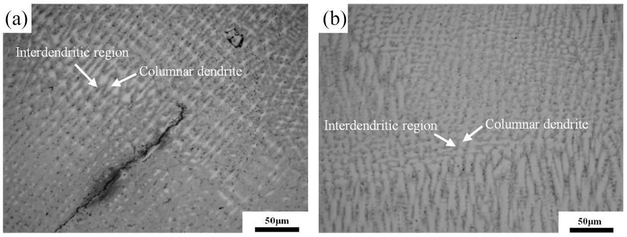
Variation of the interdendritic region size: (a) 750 °C and natural cooling and (b) 750 °C and slow cooling.
In addition, at the beginning of the cooling period after the LSF process, the temperature of the sample was still quite high. When high preheating temperature was used, it can be inferred that after the LSF process the sample would maintain its high temperature longer with increasing the time the preheating temperature was maintained for and decreasing the cooling rate. Because of the lengthy high temperature state and softening behavior of superalloy at elevated temperature, the microhardness of the sample obtained using high preheating temperature and slow cooling conditions was lower than that of the sample obtained without preheating or using a fast cooling rate. The lengthy slow cooling process was, in certain ways, similar to a stress relief annealing process. The thermal stress was gradually relieved during the slow cooling process. It is well known that the cracks form due to the competition between material ductility and internal stress. Previous studies have proved that the residual stress is related to the microhardness. Compared to hard materials with relatively poor plasticity, it is easier to relieve the stress in materials with lower hardness. The stress relief weakens the driving force of the crack formation. 17 Moreover, the molten pool would become larger in the LSF process with higher preheating temperature, and there might be a higher possibility for the cracks that occurred below the surface to be backfilled. The liquid in the molten pool may penetrate and backfill the cracks during the LSF process, which can also decrease the width and intensity of the cracks.
Further exploration of preheating and controlled cooling method
According to the crack mechanism of the LSF Rene 104 superalloy, the microsegregation and large thermal stress caused by the repeated rapid heating and cooling processes seemed to be the main reasons for cracks. Large thermal stress is common in high-energy beam processing such as LSF. For other Ni-based superalloys with high Al and Ti content, the phase transition process can also be analyzed with the same nonequilibrium phase diagram used in this article. It means that the microsegregation of Al + Ti is also a common problem when fabricating Ni-based superalloys with high Al and Ti content by LSF and this conclusion is also supported by many references.12,14,17,21 In this article, although Rene 104 superalloy was chosen as the experimental material, the effect of preheating and controlled cooling on crack defects can be attributed to the following three aspects: (1) reduction of temperature gradient in deposition direction due to the high preheating temperature, (2) a more equilibrium cooling process and a more uniform temperature field resulted from the slow cooling strategy, and (3) low hardness caused by the long high temperature state. Reduction of temperature gradient, more uniform temperature field, and low hardness of deposited part decrease the thermal stress in the LSF process. Moreover, a more equilibrium cooling process limits the microsegregation of Al and Ti in the interdendritic regions. It can be found that the common problems leading to the formation of cracks in the LSF process have been alleviated through preheating and controlled cooling. Thus, it is believed that the method of preheating and controlled cooling will also be effective when it is used in other Ni-based superalloys with high Al and Ti content. However, as for the exact parameters used in the experiments, because there are some differences in chemical composition between Rene 104 and other Ni-based superalloys, the requirements of preheating temperature and cooling rate for other Ni-based superalloys may be different and the required preheating temperature and cooling rate for other superalloys will be presented in the future.
Although the preheating and controlled cooling method was proved to be effective in eliminating crack defects based on the above experiment results, it is still a big problem to control the preheating and cooling processes when fabricating a real and much taller part. In small parts, the effect of substrate preheating is significant and the cooling rate can be controlled effectively by the heat provided from the substrate. When fabricating a real and much taller part, compared to the preheating of substrate, it is believed that controlling the cooling process is more important and difficult. As the highest temperature of the deposited part in LSF process exceeds 1300 °C (melting point of Rene 104 superalloy), if the cooling process is controlled effectively, the temperature of both the substrate and deposited part will remain high and a high base temperature can be provided for layers far from the substrate. Thus, when fabricating a tall LSF part, a self-designed furnace containing five heating board can be used. The experimental device used for fabricating tall parts and its schematic are presented in Figure 15. As shown in Figure 15, the heating board mainly consists of spiral high resistance alloy wires and thermal insulation material. Both the deposited part and substrate are surrounded by heating boards. The highest temperature in the furnace can reach 850 °C. During the fabrication of tall LSF part, in addition to the heat from the substrate, the LSF part can also absorb the heat from the surrounding heating boards. By adjusting the driving voltage of high resistance wires according to the temperature feedback signal, both the temperature in the furnace and the cooling process of deposited part can be controlled. Moreover, the height of the heating board and the number of high resistance wires in every heating board can be adjusted to suit the requirements of different LSF part heights, preheating temperatures, and cooling rates.
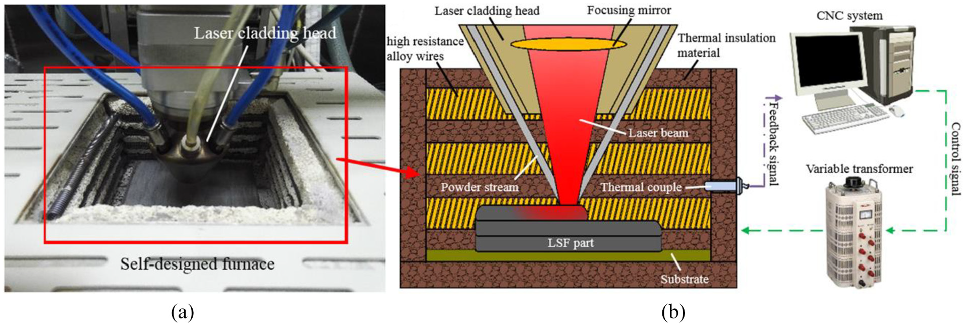
(a) The experimental device used for fabricating tall parts and (b) its schematic diagram.
Conclusion
Rene 104 superalloy parts were fabricated using LSF under different preheating and cooling conditions. The effects of the preheating and cooling processes on the crack defect and microstructure were revealed through experiments. Based on the experimental results, the following conclusions were drawn:
The microsegregation and large thermal stress caused by the repeated rapid heating and cooling processes seemed to be the main reasons for cracks in the LSF Rene 104 superalloy.
As the preheating temperature increased and the substrate cooling rate decreased, the crack intensity of the LSF samples decreased. When the cooling process was not controlled, the sample would still exhibit a severe crack problem even if the preheating temperature was increased to 750 °C. By controlling the cooling process, Rene 104 superalloy parts free of cracks can be fabricated using a relatively low preheating temperature.
The main crack suppression mechanism for controlling the preheating and cooling processes could be explained as follows: (1) the growth direction of columnar dendrites became more chaotic under high preheating temperature, which restricted crack propagation; (2) because the microsegregation of Al and Ti in the interdendritic regions decreased when the slow cooling strategy was used, there was an improvement in ductility; and (3) the low hardness caused by maintaining the high temperature state facilitated the stress relief during or after the LSF process.
Footnotes
Declaration of conflicting interests
The author(s) declared no potential conflicts of interest with respect to the research, authorship, and/or publication of this article.
Funding
The author(s) disclosed receipt of the following financial support for the research, authorship, and/or publication of this article: This work was supported by the National Key R&D Program of China (Grant No. 2018YFB1105900) and the National Natural Science Foundation of China (Grant No. 51575308).