
Abstract
Surface texturing has become a potential method to obtain a low friction coefficient under dry/lubricated conditions for different mechanical product surfaces. The mechanism of friction and wear reduction from a micro-texture on the surface of cemented carbide cutting tools was investigated by dry cutting a titanium alloy. Three kinds of micro-textures, namely, line, sinusoidal and rhombic grooves, with different area occupancy rates were produced by a laser on the cemented carbide surface. Experiments and finite element simulation of ABAQUS were used to investigate the tribological characteristics of micro-textured cemented carbide. The results indicated that the line-textured cemented carbide with an area occupancy rate of 10% showed a low friction coefficient of 0.076, which is approximately 34% of the non-textured sample. Few adhesives appeared on the textured surface, while a large number of adhesives were attached to the smooth surface after 30 min of dry friction between the cemented carbide and the titanium alloy balls. Moreover, among the three textures, the line-groove texture has the smallest friction coefficient and a good anti-wear effect. The results show that the existence of a groove texture can effectively reserve the wear debris, reduce the bond wear and weaken the furrow effect.
Keywords
Introduction
Titanium alloys possess outstanding advantages, such as high strength, high heat resistance, low density and light weight. Due to these advantages, titanium alloys are widely used in the aerospace, marine and other fields. However, titanium alloys have high chemical activity, low thermal conductivity and low elastic modulus, which cause a high cutting temperature and likely reaction with the carbide tool materials in the cutting/milling process. 1 The above characteristics of titanium alloys have significant effects on the tool life, tool consumption and wear resistance of the tool surface.2,3 At present, many scholars have shown great interest in improving the friction characteristics between the tool and the workpiece (titanium alloys) by changing the surface morphology of the tool. 4 Meanwhile, a few researchers found that great efforts can be made by laser processing technology to improve the friction properties of the surface texture existence5,6 and the micro-textures.7–11 It is reported that micro-texture on the tool surface could improve the tribological properties of the cutting tool.12,13 Lei et al. 14 studied the cutting performance of a micro-pit self-lubricating tool when cutting low carbon steel. They found that cutting fluid and a solid lubricant could effectively reduce the actual contact length of the tool and chip and the friction coefficient of the tool–chip interface. Fatima and Mativenga 15 machined a groove micro-texture on both rake and flank faces of cemented carbide tool. An orthogonal cutting experiment of alloy steel was carried out under dry cutting conditions. Results showed that the friction coefficients of the rake and flank textured tools were reduced by 17% and 18% compared with those of the non-textured tools. Su et al. 16 studied the effect of surface texture on cutting performance of high-speed cutting tools for titanium alloys. The dry cutting performance of the textured cutting tools was better than that of the conventional cutting tools. Xing et al. 17 used a laser to process the groove texture on the surface of a ceramic tool and explored the tribological characteristics under different lubrication conditions. Results show that the existence of texture can effectively reduce the friction coefficient. Lu et al. 18 prepared a groove-like micro-texture on YT15 cemented carbide tool surface with a laser and carried out friction and wear tests. The results show that the groove-like micro-texture with a certain area occupancy rate can improve the friction performance of cemented carbide surfaces.
Moreover, many scholars have studied the mechanism of friction reduction and wear reduction of micro-textured tools. 19 Kummel et al. 20 revealed that the micro-texture can reduce the contact area between the tool and the friction pair and reduce the secondary friction under unlubricated conditions. Arulkirubakaran et al. 21 reported that the existence of texture increased the heat dissipation area of the tool surface, reduced the temperature of tool–chip contact area, reduced the occurrence of adhesive wear of the tool and effectively extended the service life of the tool under unlubricated conditions. Wu et al. 22 discovered that a textured surface can capture debris generated during the friction process. Hao et al. 23 found that the texture plays a role in the continuous oil supply to the contact surface to reduce the friction coefficient of the tool–chip interface under lubricated conditions. Deng et al. 24 proposed a kind of self-lubricating tool that effectively improved tool wear and increased tool life.
Although few studies25,26 have been carried out on the friction performance of surface textures, several problems still need to be solved. The relationship between the geometric characteristics of the surface textures and the friction mechanism has not been widely investigated, and this article would combine the methods of friction and wear tests and friction simulation to explore the tribological properties. Three kinds of grooved textures (line,21,27 sinusoidal12,28 and rhombic)29,30 with different area occupancy rates were fabricated on the surface of the cemented carbide with a laser. Dry friction and wear experiments were carried out with titanium alloy balls under different loads. ABAQUS was used to simulate and analyze the stress and temperature changes of different textured cemented carbides and titanium alloys during the friction process. The friction and wear properties of different textures on the cemented carbide surfaces and titanium alloys were investigated.
Materials and experimental procedures
Preparation of samples
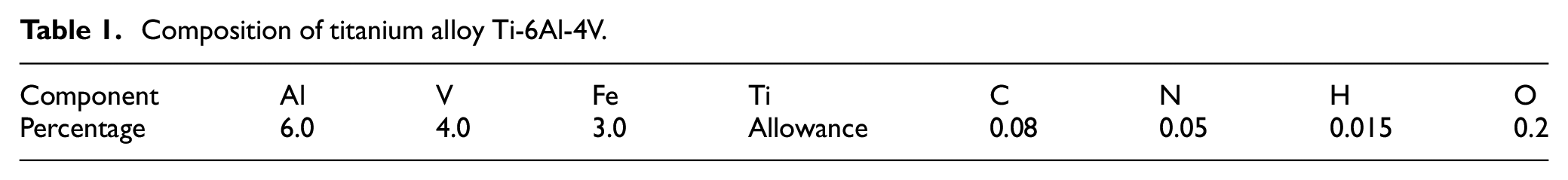
Titanium alloy balls were made of TC4 alloy with a diameter of 6 mm. The composition of the material is shown in Table 1. The titanium alloy balls were cleaned in petroleum ether and anhydrous ethanol for 10 min with a KQ2200DE numerical control ultrasonic cleaner before the experiment. Finally, a self-controlled infrared drying furnace was used to dry the samples. The surface roughness of the treated titanium alloy ball measured by a TIME3220 surface roughness instrument was less than 0.025 μm.
Composition of titanium alloy Ti-6Al-4V.
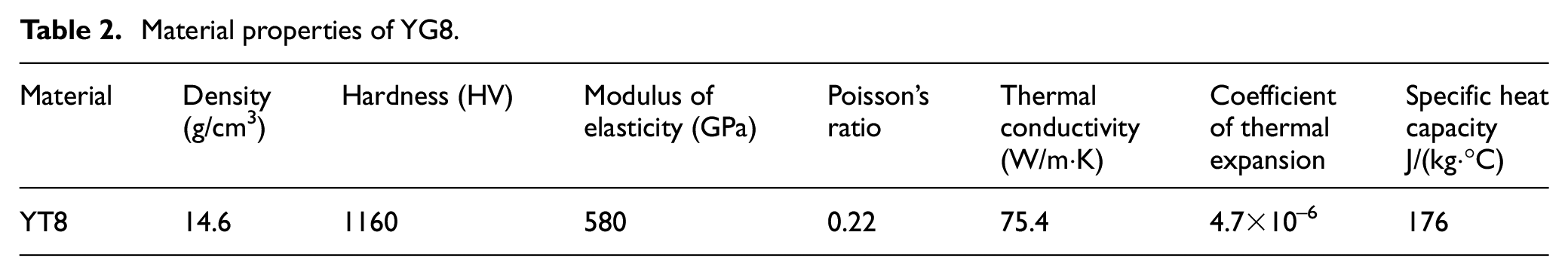
The carbide specimens were commercial cemented carbide blank with a size of 35 mm × 35 mm × 5 mm, and their surface roughness of the working area measured by a TIME3220 surface roughness instrument was about 0.03 μm. The properties of the cemented carbide are listed in Table 2. A laser marking machine was used to machine the line-, sinusoidal- and rhombic-groove textures on the surface of the cemented carbide with an area occupancy rate of 10%, 20% and 30%, respectively. The surface morphology of the texture is shown in Figure 1. The laser pulses were generated using a laser system at a center wavelength of 1064 nm, repetition rate of 20 kHz and pulse duration of approximately 10 ns. The machining was accomplished in air with a power of 40 W, scanning speed of 100 mm/s and scanning time of 200. The processed textures had a width of 159.599 μm and a depth of 14.590 μm. The textured surface of the cemented carbide was in turn polished with 1200 and 2000 mesh sandpaper. When the surface roughness of the textured specimens was less than 1 μm, polishing was stopped. Then, the samples were cleaned in petroleum ether and anhydrous ethanol by NC ultrasonic cleaner for 10 min and dried in self-controlled infrared drying furnace. The three-dimensional shape of the line-groove texture is shown in Figure 2, which was observed by a DSX510 stereomicroscope (OLYMPUS). A laser beam with a Gaussian energy distribution was used to process the specimens. The texture is deep in the middle (as shown at point C in Figure 2(c)), and the sides are shallow (as shown at point B in Figure 2(c)). The melting and vaporization of the material at high temperature during laser processing cause liquid explosion, which causes the molten metal to form a large amount of molten material around the microgroove. The molten material is deposited in the texture because the molten material cannot be removed in time. The side is formed with a protrusion, 31 and the treated protrusion is shown at point A in Figure 2(c), and the height of the protrusion on both sides is 2.582 μm. The deposition of the melt forms a heat-affected zone on both sides of the groove texture of the cemented carbide surface. The width of the heat-affected zone on one side is 45.207 μm, and the area accounts for 56.65% of the entire groove texture. The texture produced by the laser due to the removal of the material actually forms a groove width of only 69.185 μm on the surface of the cemented carbide.
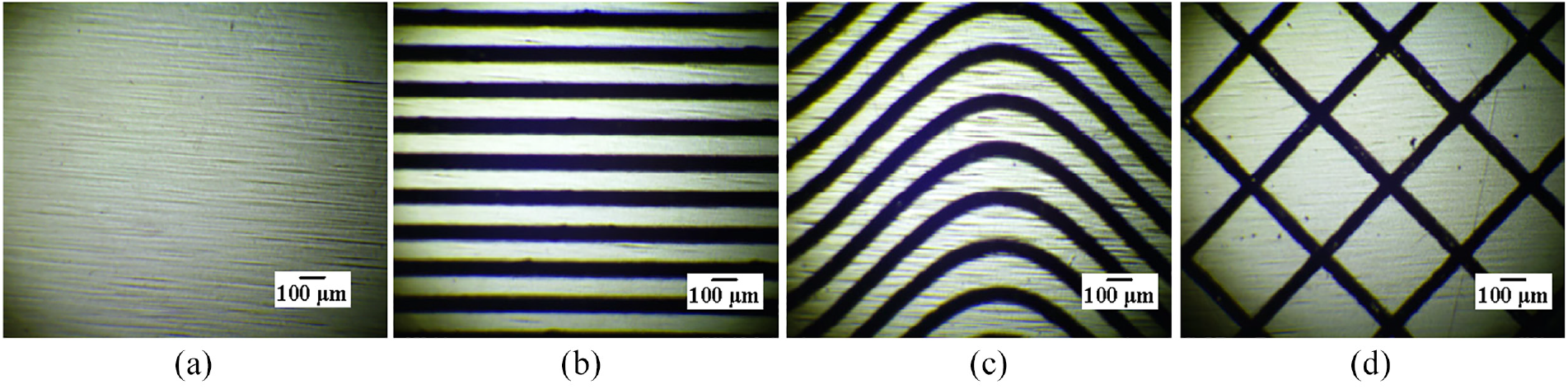
Surface topography of cemented carbide with smooth surface and textured surface with an area occupancy rate of 30%: (a) smooth surface, SS; (b) line-groove textured surface, ST-LG; (c) sinusoidal-groove textured surface, ST-SG; and (d) rhombic-groove textured surface, ST-RG.
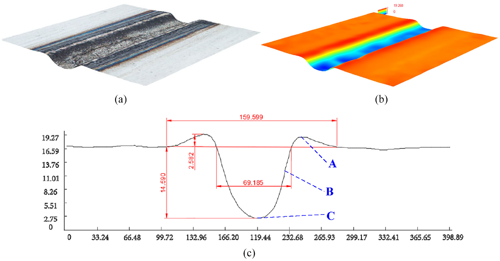
(a, b) Three-dimensional morphology of line groove texture and (c) dimension of a groove texture.
Material properties of YG8.
Friction and wear tests
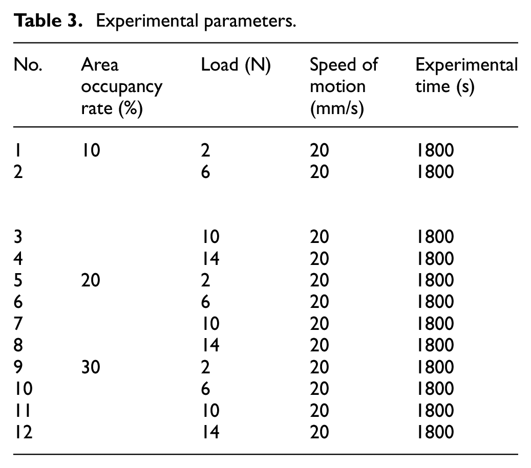
The MFT-EC4000 instrument was used for electrochemical corrosion and friction testing. The surface morphology after friction and wear was observed by scanning electron microscope (SEM). The cemented carbide sample was fixed in the special fixture of the chassis, and the titanium alloy ball was fixed in the upper mechanical clamp. The load was applied vertically on the titanium alloy ball by applying a weight, and the cemented carbide disk was made to reciprocate in a line motion with a sliding distance of 5 mm. The rubbing directions were perpendicular to the line groove, the centerline of the sinusoidal groove and the diagonal line of the rhombic groove. A total of 12 sets of experiments were carried out on the smooth surface and the textured surface with line-, sinusoidal- and rhombic grooves of the cemented carbide material according to the experimental parameters listed in Table 3. Each experiment was repeated three times, and the experimental dates were averaged. The experiments were all carried out under dry friction conditions.
Experimental parameters.
Influence of texture type
The variations of the friction coefficients are shown in Figure 3. The overall friction coefficient of the line-textured sample (ST-LG) during the friction process is much smaller than that of the smooth sample (SS), and the average friction coefficient of the line-textured sample is only 0.076. The average coefficient of friction 0.219 is reduced by 65.29%, which is relative to the smooth sample. The average friction coefficients of the sinusoidal-textured sample (ST-SG) and the rhombic-textured sample (ST-RG) during the friction process are close to that of the smooth sample. The friction coefficient of the groove-textured sample is relatively stable, while the smooth sample friction coefficient fluctuates greatly. The maximum fluctuation of the friction coefficient of the smooth sample appears between A and B, which is 0.242. The friction coefficient of the textured sample began to stabilize after 100 s of friction. The friction coefficient of the smooth sample is temporarily stable at 200 s, and the friction coefficient begins to fluctuate in a large range after running to 1000 s. The friction coefficient of the groove-textured cemented carbide varies slightly during the whole friction process, while the friction coefficient of the smooth sample fluctuates greatly.
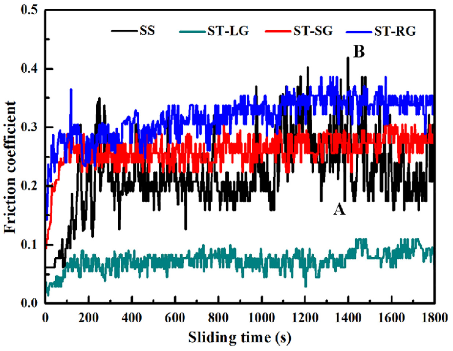
Friction coefficient of smooth surface and textured surface with an area occupancy rate of 10% on the cemented carbide when the sliding speed is 20 mm/s and the load is 2 N.
Figure 4(a) shows the SEM image of the morphology of the cemented carbide with a smooth surface. The wear marks are wide, and the surface has a large amount of bonds. From the enlarged view of a bond in Figure 4(b), it can be seen that the block-like bond is superposed by a layer of bonds, which have irregular shapes, cracks, a large area, a large volume and a certain height. The energy-dispersive X-ray (EDX) spectrum analysis of bond 1 is shown in Figure 5(a), in which Ti accounts for 35.62% and O accounts for 23.45%. It can be inferred that the bond is a hard and brittle layer formed by the chemical reaction of the Ti in the titanium alloy ball with O in the air at a high friction temperature, and it is tightly bonded to the surface of the cemented carbide. The cracks in the bond increase and are eventually removed from the surface of the cemented carbide with the friction process.
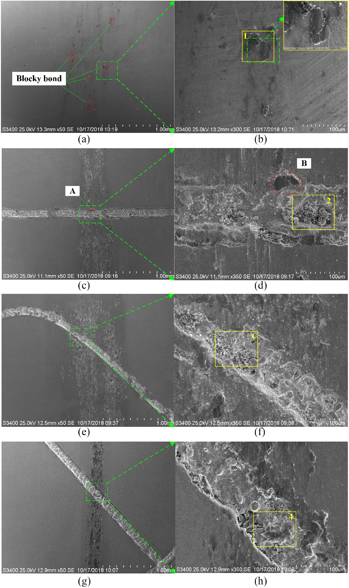
SEM micrographs of different kinds of textured cemented carbide when the load is 2 N and the sliding speed is 20 mm/s: (a, b) SS, (c, d) ST-LG, (e, f) ST-SG and (g, h) ST-RG.
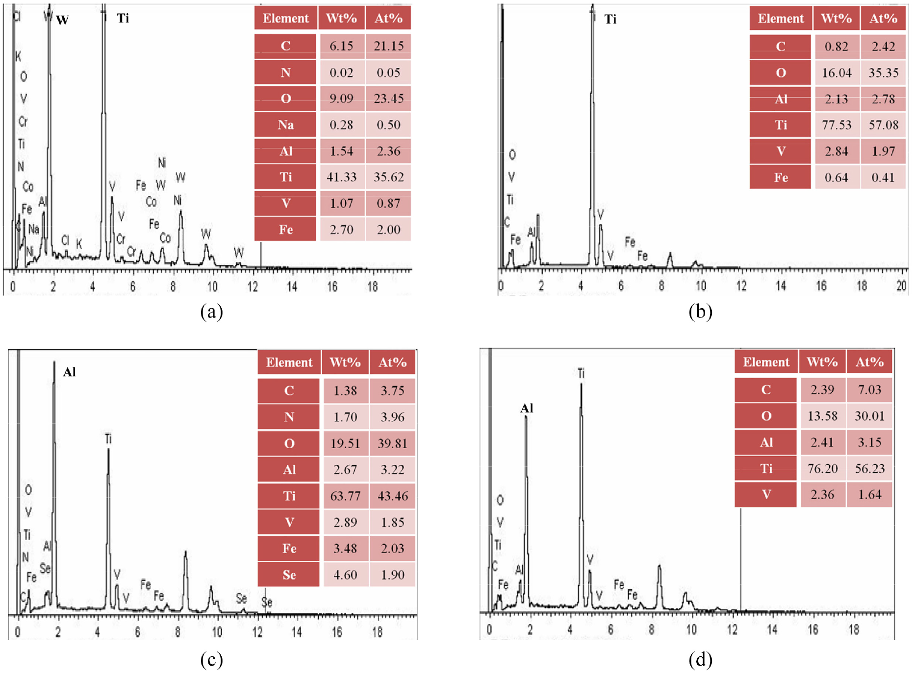
EDX spectrum after friction on the cemented carbide surface: (a) EDX energy spectrum at point 1 in Figure 7(b); (b) EDX energy spectrum at point 2 in Figure 7(d); (c) EDX energy spectrum at point 3 in Figure 7(f); and (d) EDX energy spectrum at point 4 in Figure 7(h).
Figure 4(c) shows the SEM image of the morphology of the cemented carbide with a line-groove texture after wear. The wear marks are narrow and shallow, and there are many black objects in the wear marks. B in Figure 4(d) is a magnified view of the black object. The black object has a small volume with a dark color. There was a chemical reaction between the titanium alloy wear debris and oxygen. The bond is thin and has no cracks. Figure 4(d) is an enlarged view of the groove in Figure 4(c). Figure 4(d) shows that the groove contains a substantial amount of abrasive debris. Some areas have been filled with abrasive debris. The outline of the line groove was changed due to the bonding between the two sides of the groove, and there are also microcracks in the bond.
Figure 4(e) shows the SEM image of the morphology of the sinusoidal-groove cemented carbide surface after wear. The wear marks are the widest among the four wear surfaces, and there are some black objects in the wear scar. The enlarged view of the sinusoidal-groove texture in Figure 4(f) shows that the black object near the texture is a small-area bond. There are many bonds in the grooved texture. The bonds on both sides of the groove were joined, and there are cracks in the bonds.
Figure 4(g) shows the SEM morphology of the surface of the rhombic-groove cemented carbide after wear. The wear marks are the narrowest among the four wear surfaces, but many black bonds appear. Figure 4(h) is a magnified view of the rhombic groove. From Figure 4, it can be seen that the black bond on both sides of the groove is densely distributed, but the black bond is thin, and a small part of the bond is stacked. Inside the rhombic groove, the bond is small and scattered. EDX spectra of three types of grooves are analyzed as shown in Figure 5(b)–(d). There is a substantial amount of Ti and O in the groove in addition to a small amount of Al. In the three kinds of grooves, in addition to the titanium oxide binder, there is also wear debris from the titanium alloy ball.
The smooth surface contains a large amount of bonds compared with the textured surface. The bond is layered and stacked, which causes severe wear on the titanium alloy balls. The three kinds of grooves contain a large amount of titanium chips. The texture can store the wear debris effectively so that a small number of surface bonds appeared. According to the energy spectrum analysis and texture enlargement diagram of the three kinds of grooved texture, the sinusoidal-groove texture has the largest amount of binder and the largest area.
Figure 6(a) shows the wear morphology from the sliding of the titanium alloy ball on a smooth surface sample. The wear volume of the titanium alloy ball is small, but the wear scar is severe. The wear volume of the titanium alloy ball is reduced by 25% compared with the surface of the line texture in Figure 6(c). From the magnified view of Figure 6(b), it can be seen that there are more irregular deep grooves and more surface deposits. The area of the wear mark is large, as shown in Figure 6(b). Figure 6(c) shows the wear morphology of the titanium alloy ball with the line-groove textured surface. The enlarged view of the wear mark in Figure 6(d) shows that the wear surface has no large bonds and deep grooves. Figure 6(e) shows the wear morphology of the titanium alloy ball sliding with the sinusoidal-groove textured surface, and the surface contains many white particles. An enlarged image of the wear morphology is shown in Figure 6(f). For the abrasive particles adhering to the surface of the titanium alloy ball, there is no bond or deep groove on the surface of the wear mark. Figure 6(g) shows the surface morphology of the titanium alloy ball sliding with the rhombic-groove textured surface. Figure 6(h) shows an enlarged image of the wear scar. There are few grooves on the surface of the titanium alloy sphere in this image, but small amount of adhesives are attached to the surface.
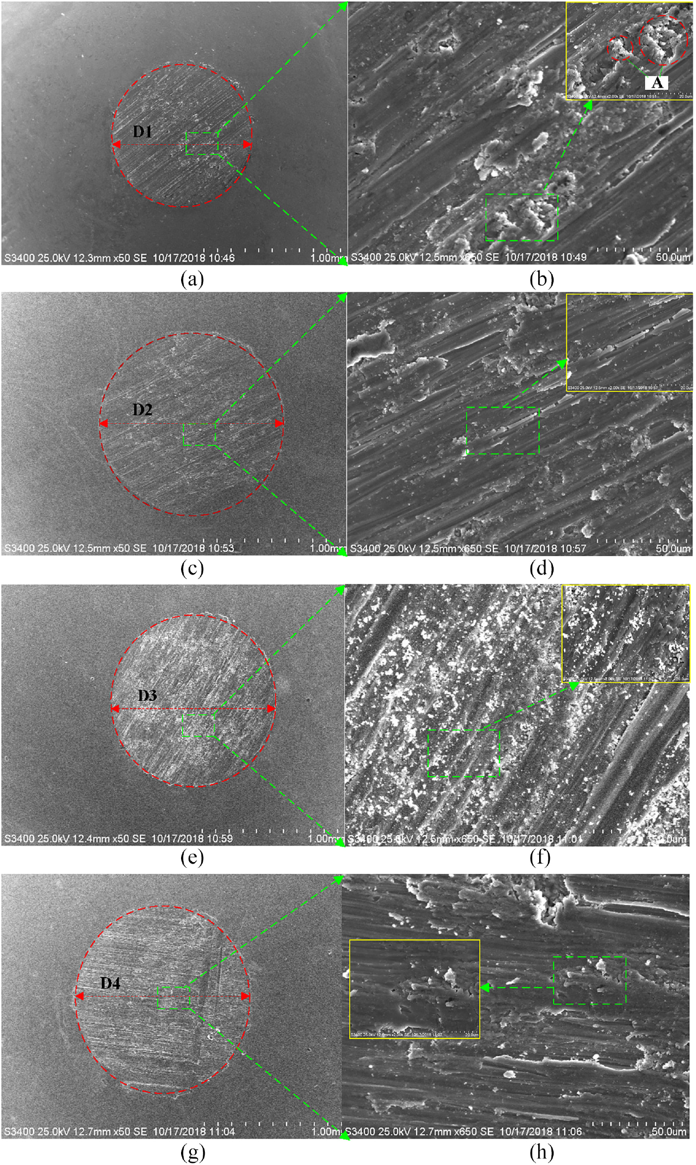
SEM micrographs of titanium alloy balls after friction with smooth surface and textured surface of cemented carbide (D1 = 1000 μm, D2 = 1338 μm, D3 = 1232 μm and D4 = 1267 μm): (a, b) SS, (c, d) SS-LG, (e, f) SS-SG and (g, h) SS-RG.
Influence of area occupancy and load
Figure 7(a) shows that, with increasing area occupancy, the friction coefficient of the groove texture increases. The friction coefficient of the line-textured sample increases by 26.8%, while the friction coefficients of the sinusoidal- and rhombic-textured samples increase slightly. When the load increases, the friction coefficient of the rhombic-textured sample is less affected by a change in the load. When the load increases continuously, the friction coefficient of the rhombic-textured sample fluctuates slightly with a change in the area occupancy, the friction coefficient of the line-textured sample first increases and then decreases with increasing area occupancy.
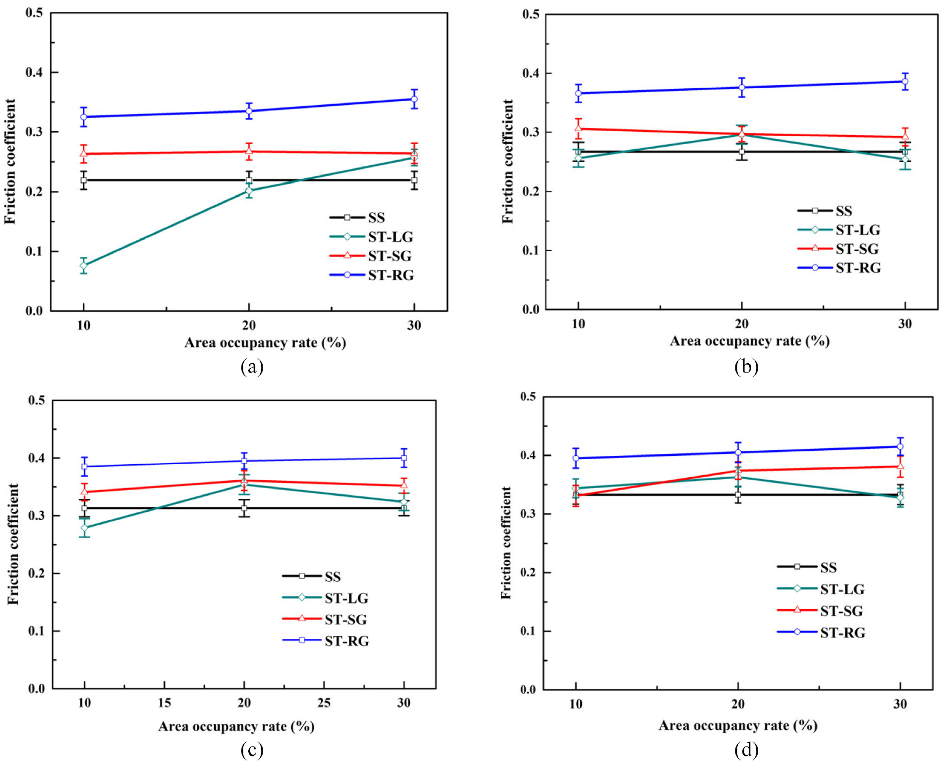
Friction coefficient of different kinds of samples under different area occupancy rates and loads: (a) 2 N, (b) 6 N, (c) 10 N and (d) 14 N.
In Figure 8, the friction coefficient of the smooth cemented carbide increases with increasing load. The friction coefficient of the rhombic-textured sample shows the same trend with the increasing load, but the overall friction coefficient is larger than that of the smooth surface. The friction coefficient of the line-textured sample is obviously smaller than that of the smooth sample when the load is 2 and 10 N, and the friction reduction is obvious. The friction coefficient of the sinusoidal-textured sample increases first and then decreases with increasing load. When the load is 14 N, it has an anti-friction effect.
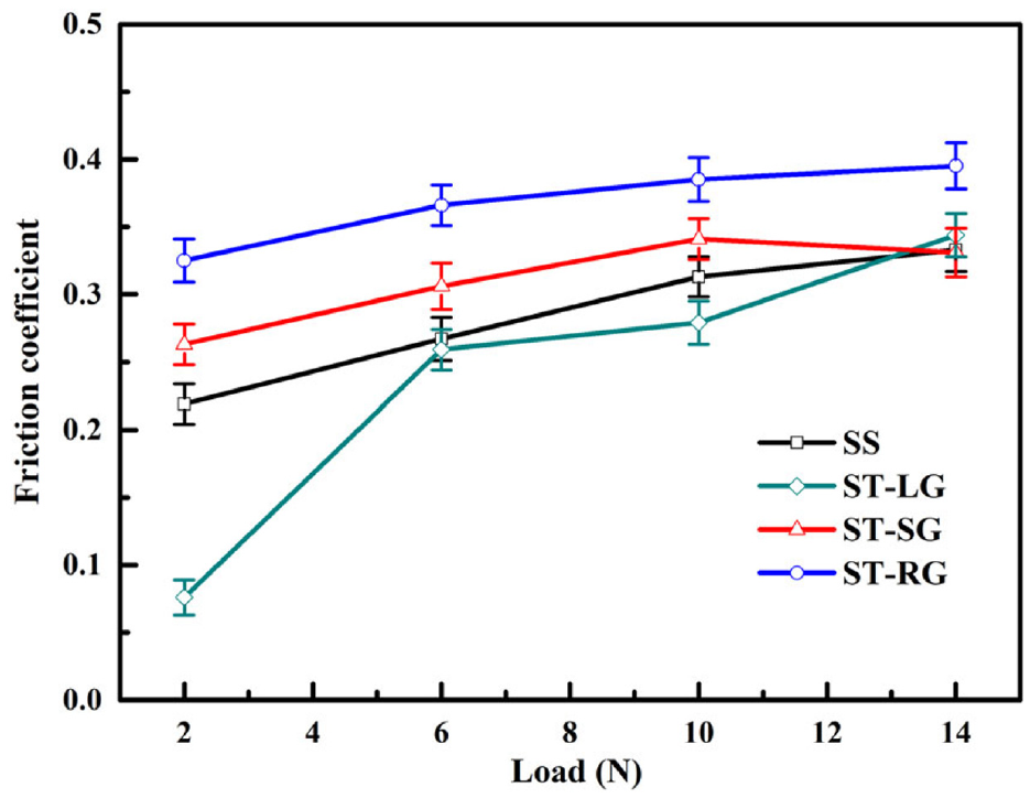
Friction coefficient of different kinds of samples under different loads at a speed of 20 mm/s.
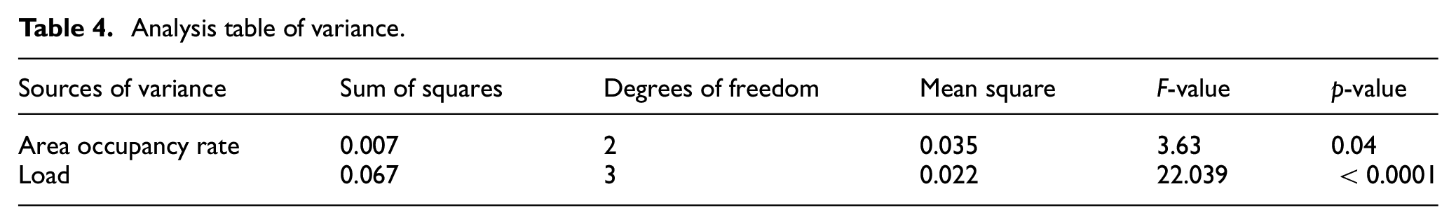
The main effect diagram of friction coefficient is shown in Figure 9. In the figure, the load has more significant effect on friction coefficient than area occupancy rate. The variance of results analysis is shown in Table 4. Both area occupancy rate and load were considered as reliable experimental factors in this study (p < 0.05).
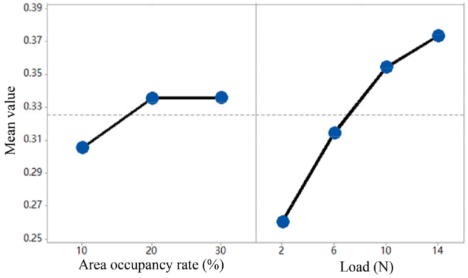
Main effect diagram of friction coefficient.
Analysis table of variance.
Simulation analysis by ABAQUS
In the friction process between the tool surface and the chip, according to formula (1), it can be seen that the friction coefficient is directly proportional to the friction stress, which can reflect the change of friction coefficient to a certain extent

where
In order to further explore the mechanism of texture in the friction process between the tool and the chip, a three-dimensional friction simulation model for titanium alloy processing was established by ABAQUS. The stress and temperature variations during the friction process between the micro-textured cemented carbide tool and the titanium alloy material were studied.
Establishment of three-dimensional simulation model
In the ball–disk reciprocating line motion friction and wear experiments, the load was applied to the ball and the carbide disk had a reciprocating line motion. The three-dimensional simplified model is shown in Figure 10. Ti-6Al-4V was chosen as the material for the upper sample, and cemented carbide YG8 was chosen for the lower sample. The line, sinusoidal and rhombic grooves were fabricated on the surface of different samples of cemented carbide YG8. The model is established as follows:
In ABAQUS software part module, cuboids with dimensions of 3 mm × 1 mm × 0.3 mm and cylinders with dimensions of 0.4 mm × 0.3 mm are created. Assembling of parts together is shown in Figure 10.
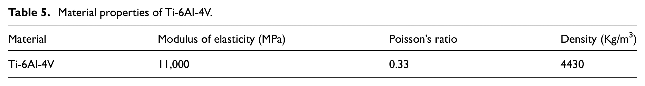
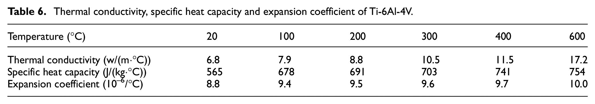
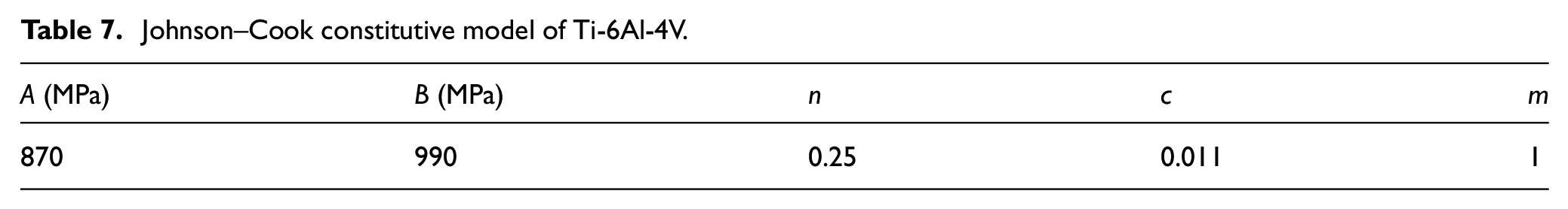
The properties of cemented carbide YG8 and Ti-6Al-4V were given to the lower samples and the upper samples, respectively. The properties of YG8 material are shown in Table 2. The properties of Ti-6Al-4V are shown in Tables 5 and 6. In this simulation, the Johnson–Cook constitutive equation (shown in formula (2)) is used as the material model for Ti-6Al-4V alloy, and the parameters are shown in Table 7
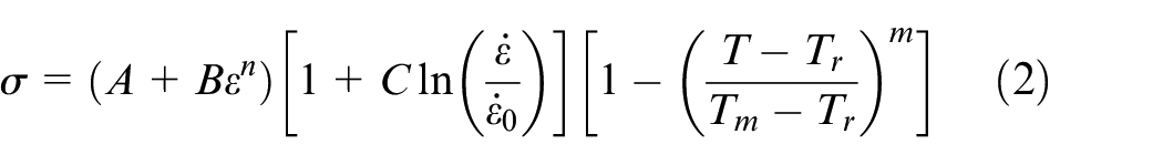
where
3. The friction contact between YG8 and titanium alloy specimens is created. Ignoring the geometric and material nonlinearities involved in the contact, the pure boundary nonlinearity is considered. 33 The modified Coulomb friction model is used for friction contact as shown in formula (3)
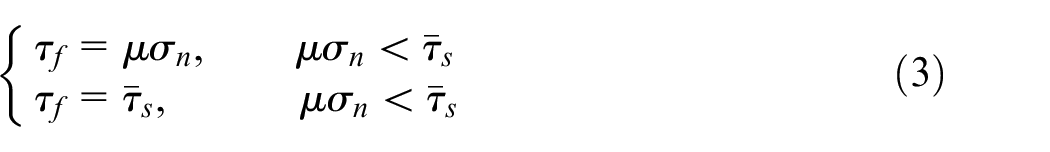
where μ is the friction coefficient, which is 0.219. The heat transfer coefficient of the film is 100 when the heat exchange condition is set.
4. A pressure of 1.989 × 10⁷ is applied on the top of the titanium alloy sample, and the displacement and rotation in the X and Y directions of the titanium alloy sample are fixed. The velocity in the X direction of the cemented carbide is –20 mm/s. The initial temperature is set to 20 °C.
5. The hexahedral mesh is chosen for the titanium alloy sample mesh. The mesh element type is temperature–displacement coupling, and the reduction integration is selected. The mesh size is 1.95 × 10⁻⁹. The grid setting of the cemented carbide sample is same as that of the titanium alloy.
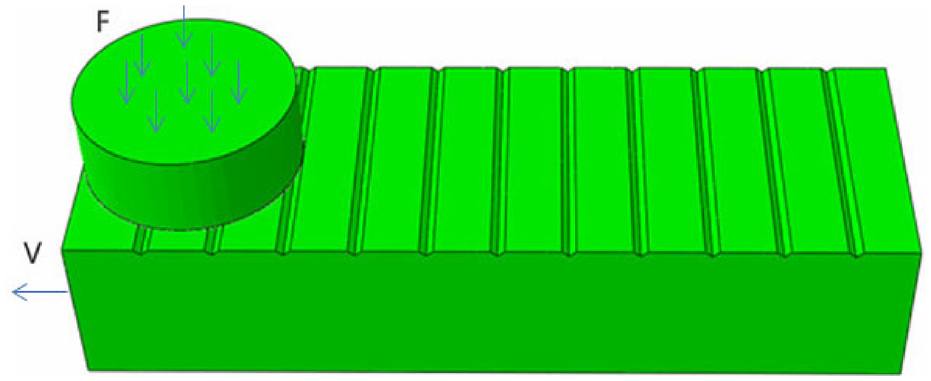
Simplified model of three-dimensional simulation.
Material properties of Ti-6Al-4V.
Thermal conductivity, specific heat capacity and expansion coefficient of Ti-6Al-4V.
Johnson–Cook constitutive model of Ti-6Al-4V.
Results of simulation
Figure 11(a) shows that a smooth surface stress is concentrated in a large area in the frictional contact area. The maximum stress in this area is 3.5 × 10⁸ Pa, and the outward stress decreases in turn with the maximum stress area at the center. Figure 11(b)–(d) shows that the stress concentration on the surface of the three kinds of groove textures is distributed on both sides of the groove textures, and the area of the stress concentration is small. The maximum stress on the surface of the line and sinusoidal grooves decreased by 65% and 71%, respectively, compared with the smooth surface.
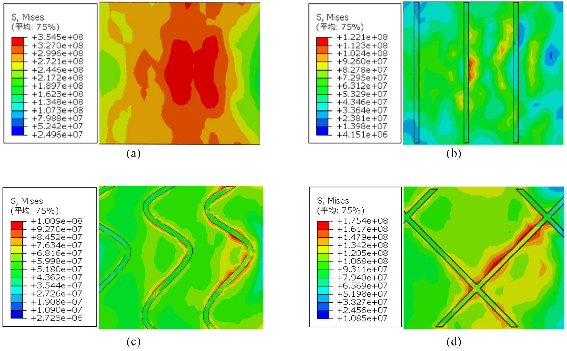
Stress distribution on smooth surface and textured surface: (a) smooth surface, SS; (b) line-groove textured surface, ST-LG; (c) sinusoidal-groove textured surface, ST-SG; and (d) rhombic-groove textured surface, ST-RG.
Figure 12(a) shows that the temperature of the titanium alloy sliding against the smooth cemented carbide is centrifugally distributed in the middle of the contact zone. The average temperature of the contact zone is 40.21 °C, which is 20.21 °C higher than that before friction. Figure 12(b)–(d) shows the surface temperature of the titanium alloy sliding with cemented carbides with different textures. Among them, the maximum temperature of the surface of the titanium alloy sliding with the line-groove textured surface decreases by 18% compared with that of the smooth surface. The temperature distribution on the surface of the titanium alloy in Figure 12(c) and (d) shows few changes compared with that in Figure 12(a). The area of the temperature concentration on the surface of the titanium alloy when sliding with a sinusoidal-groove textured surface increases, as shown in Figure 12(b).
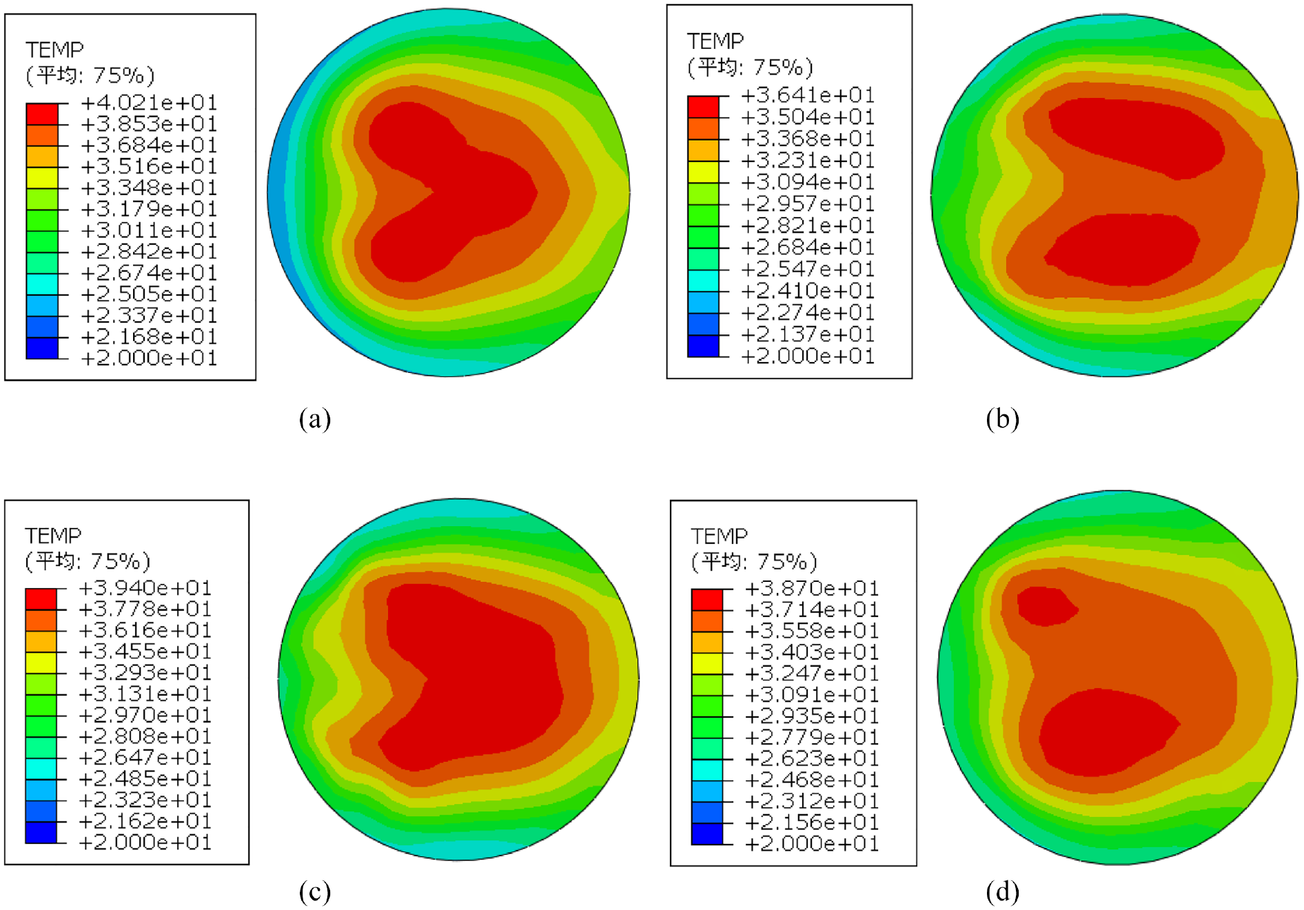
Surface temperature distribution of titanium alloys: (a) SS, (b) ST-LG, (c) ST-LG and (d) ST-RG.
Discussion
At the beginning of the friction process, the contact area between the smooth surface of the cemented carbide and the titanium alloy is smaller, and the friction coefficient is smaller. With the development of friction, more debris is produced. As shown in Figure 13(a), the friction sketch shows that the debris remains on the surface of the cemented carbide. With the increase in wear, friction increases and friction coefficient also increases.
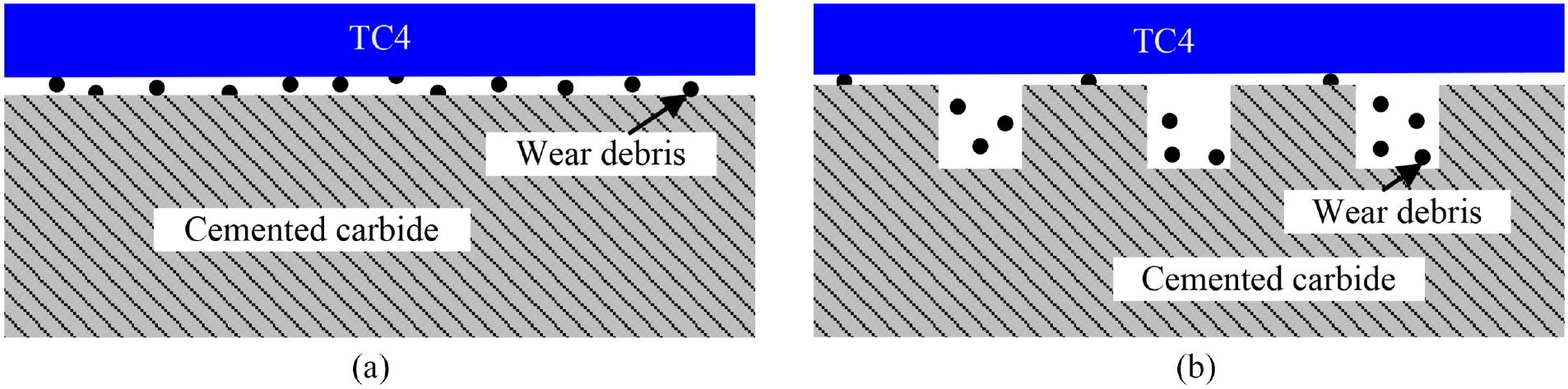
Schematic diagram of friction: (a) smooth sample, SS, and (b) textured sample, ST.
The surface roughness of the cemented carbide increases because of the existence of texture, and the edge bulge of groove texture on the surface of the cemented carbide has a slight cutting effect on the titanium alloy ball. So, when the textured cemented carbide sample and the titanium alloy sample start to friction, the wear of the texture specimen will be aggravated during early friction processing and the friction coefficient will increase greatly at this time. As shown in Figure 13(b), the existence of groove texture can effectively reserve debris generated during friction and reduce the amount of debris on the surface of the friction pairs.
Figure 14 shows the average surface stress and friction coefficient of different kinds of cemented carbide samples. Line-textured sample shows the minimum friction coefficient and the minimum average stress compared with smooth surface sample, sinusoidal-textured sample and rhombic-textured sample. The changes in the surface stress and friction coefficient of the four kinds of cemented carbide samples show the same trend. The simulation can reveal the influence of the existence of the texture on the tool surface stress to a certain extent. The simulation results of ABAQUS show that the existence of three kinds of groove textures—line, sinusoidal and rhombic—effectively avoids the phenomenon of large area stress concentration on the smooth surface of the cemented carbide. The stress concentration is distributed on both sides of the groove texture of the textured sample, and the stress value decreases relative to the smooth surface. Among the three kinds of textured surfaces, the stress concentration area of the line texture is the smallest and the sinusoidal texture is the lowest.
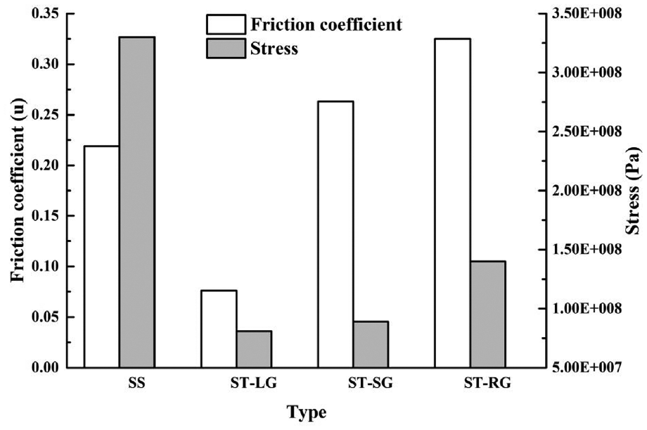
Surface average stress and friction coefficient of different kinds of cemented carbide samples.
The existence of texture effectively enlarges the heat dissipation area and can discharge heat generated in the friction process. The simulation results show that the friction temperatures of the three textured surfaces are lower than those of the smooth surface. Among them, the temperature concentration area of the rhombic-groove textured surface is the smallest and the friction temperature of the line-groove textured surface is the lowest.
As a result of the friction between the titanium alloy and the smooth cemented carbide surfaces, a large amount of wear debris is generated. The wear debris cannot be removed in time, and it adheres to the surface of the cemented carbide. As the friction continues, the temperature continuously increases, the titanium alloy reacts with O at a high temperature, and a hard and brittle layer of titanium oxide is formed on the surface of the cemented carbide. The surface of the cemented carbide is rough due to the adhesion of titanium oxide to the surface of the cemented carbide, and bond wear occurs. Wear debris generated during friction of titanium alloy and textured samples accumulated in the groove texture. The weight percentage of Ti in the line texture is as high as 77.53%. The presence of the groove effectively collects the abrasive chips, so the amount of surface wear is greatly reduced, and no block-like bond is formed on the surface. Although the anti-friction effect of the sinusoidal and rhomboid textures is not obvious, the friction coefficient of the textured surface is very stable because the grooved texture can effectively collect the wear debris and reduce the surface adhesion.
When the worn titanium alloy ball and the cemented carbide continue to rub, the contact point between the cemented carbide and the titanium alloy may generate an instantaneous high temperature, causing the contact surface to adhere. Under the action of friction, the adhesive node is sheared and produces slip. When the rough peak of the cemented carbide tool surface is embedded in the soft metal on the surface of the chip, the soft metal is pushed during the sliding process to make it flow plastically and plow out a piece. The furrow effect occurs in the groove, and the resistance of the furrow effect is also a component of the friction force. Therefore, the friction from the sliding of the titanium alloy on the surface of the cemented carbide tool material is affected by the formation of the adhesive joint and the shearing and furrow effect. The surface quality of the titanium alloy ball with a smooth surface is poor. When the groove-textured surface of the cemented carbide slides against the titanium alloy, the protrusions on both sides of the texture have a slight cutting effect on the titanium alloy and accelerate the wear of the titanium alloy ball. Therefore, the wear volume of the titanium alloy ball is large when the groove-textured surface slides against the textured cemented carbide (as shown in Figure 6(c), (e) and (g)). At the same time, the groove texture on the surface of the cemented carbide can collect debris generated during the friction process and reduce debris on the contact surface between the cemented carbide and the titanium alloy, thereby weakening the furrow effect and improving the surface quality of the titanium alloy. The micro-texture plays an important role in reducing wear and improving the adhesion and wear resistance of the cemented carbide tool materials.
The pressure per unit area increases as the texture area occupancy increases when the load remains constant, which accelerates wear. However, as the area occupancy rate increases, the heat dissipation capability of the textured surface and the ability to collect the abrasive chips are enhanced, which reduces the occurrence of the bond wear. When the area occupancy rate is constant and the load increases, the increase in unit area pressure in the contact area leads to the increase in wear debris, so the bonding wear phenomenon of the smooth surface is more serious, but the effect of texture collecting wear debris is more significant. The texture morphology and area occupancy significantly affect the dry friction and wear behavior between the cemented carbide and the titanium alloy. These effects mainly depend on the combination of the wear debris in the groove to reduce the three-body wear damage and the increase in the contact stress of the textured friction surface to increase the wear. The results are similar to what was reported in Sun et al. 34 Therefore, under different friction conditions, a reasonable texture type and area occupancy rate should be selected to reduce the friction coefficient, reduce the occurrence of bond wear and improve the surface quality of the grinding parts.
When friction occurs between the textured cemented carbide surface and the titanium alloy ball, the existence of a grooved texture reduces the contact area with the titanium alloy, thereby reducing the friction force and friction coefficient. The existence of the grooved texture effectively collects the grinding debris, effectively dissipates heat, reduces the occurrence of surface bonding, weakens the furrow effect and improves the surface quality of the titanium alloy.
Conclusion
Based on the above analysis, the following conclusions can be drawn:
When friction occurs between the three kinds of groove textures, namely, line, sinusoidal and rhombic, the friction reduction effect of the line groove is the most obvious. When the load is 2 N, the friction speed is 20 mm/s and the friction time is half an hour, the line-groove textured surface with an area occupancy rate of 10% has the low friction coefficient of 0.076, which is 34% of the smooth surface friction coefficient of 0.219. Moreover, during the whole friction process, the friction coefficient of the groove-textured cemented carbide surface changes slightly, while the friction coefficient of the smooth surface fluctuates greatly.
The existence of texture has obvious effect on reducing the friction strength between contact interfaces, mainly because the texture can store wear debris, dissipate heat effectively and decrease the occurrence of bond wear.
The existence of micro-texture on the surface of the tool reduces the occurrence of surface bonding of the titanium alloy on the workpiece and reduces the furrow effect. The surface roughness of the titanium alloy after friction and wear is low, and the surface quality is improved.
The texture parameters and texture morphology of the surface micro-texture significantly affect the tribological properties of cemented carbide and titanium alloy. Therefore, under different friction conditions, micro-textures with different area occupancies and types should be selected to reduce the friction coefficient in the friction process, reduce the occurrence of bond wear, improve the surface quality of titanium alloys and prolong the life of the tool.
Footnotes
Acknowledgements
The authors thank engineer Jingjie Dai for his great help with the SEM.
Declaration of conflicting interests
The author(s) declared no potential conflicts of interest with respect to the research, authorship, and/or publication of this article.
Funding
The author(s) disclosed receipt of the following financial support for the research, authorship, and/or publication of this article: This work was supported by the National Natural Science Foundation of Shandong (grant nos ZR2018PEE011 and ZR2019MEE059).