
Abstract
Simulation of brittle regime machining of materials (such as ceramics) is often difficult because of the complex material removal mechanisms involved. In this study, the discrete element method is used to simulate the dynamic process for machining of slip-cast fused silica ceramics. Flat-joint contact model is exploited to model contacts between particles in synthetic discrete element method models. This contact model is suitable for modeling of brittle materials with high ratios (higher than 10) of unconfined compressive strength to tensile strength. The discrete element method has the ability to simulate initiation, propagation, and coalescence of cracks leading to chip formation in the brittle regime of cutting. Applying the discrete element method, the influences of operating conditions on the creation of surface/subsurface damages, chip formation, and cutting forces are studied. It is shown that the parameters of the material model determined from conventional calibration tests do not provide quantitatively accurate prediction of cutting forces. As such, model updating is carried out using the forces obtained in the cutting experiments, and the numerical results are verified against experimental cutting forces. The differences between experimental and numerical machining forces are in the range of 10%–30%. Finally, the results of discrete element method simulations reveal that the nature of micro-crack propagation is brittle in the machining process of ceramics.
Introduction
The use of ceramic parts in various applications is increasing due to their superior physical and mechanical properties such as high melting temperature, low thermal conductivity, low electrical conductivity, chemical stability, high corrosion resistance, and high wear resistance. However, machining of ceramic parts is often a challenging task because of its inherent hardness and brittle nature. There is a vast body of literature on ceramic machining which focus on overcoming their machining difficulties.1–4 Problems such as surface and subsurface damages are common in machining of ceramic materials.5–7 Therefore, it is worthwhile to model the machining process of ceramics to gain better understanding of the effects of various parameters on the quality of the machined ceramic part.
Few studies have been conducted to model brittle regime machining of ceramic materials. In contrast, ductile regime machining is usually modeled using the finite element method (FEM). For instance, Kumbera et al. 8 simulated the machining of silicon nitride ceramics at the micrometer scale in ductile regime utilizing FEM. Brittle regime machining of ceramics causes a large number of cracks and damages which are difficult to model using FEM.
The discrete element method (DEM) is a better alternative to the FEM analysis in modeling of the behavior of brittle materials. The DEM was first introduced by Cundall 9 to analyze rock mechanics problems. It simulates a brittle material as a collection of compacted particles with interactions between them. The particle flow code (PFC) is an explicit dynamic implementation of DEM. In the PFC, particles are assumed to be rigid, and the shape of each particle is usually a disk (in two-dimensional (2D)) or a sphere (in three-dimensional (3D)). Potyondy and Cundall 10 presented a bonded-particle model (BPM) based on DEM theories for rock. In the BPM, particles can move (rotate and translate) independent of each other, while bonds can exist at contact points between them (particles interact only at contact points). Bonds have limited strengths and can break under load. In the BPM, a crack forms when a bond breaks. When broken bonds increase, cracks propagate, and may coalesce to separate sections from the compacted particles and form fragments. Hence, the crack formation mechanism in the DEM is much easier than that in the FEM. In synthetic samples composed of bonded particles, there are completely different crack patterns for tensile and compressive (confined and unconfined) tests. Moreover, micro-cracks and localized macro-fractures occur spontaneously. Reproducing these phenomena by continuum-based models (e.g. FEM) is often inefficient. 10
Although the DEM method can be used to model ceramics in various applications, here, only the literature on the application of DEM in machining of ceramics is briefly reviewed. Tan et al. 11 utilized DEM to simulate crack initiation and propagation in polycrystalline Al2O3 during the machining process. Their simulation results demonstrated that cracks are initiated right under or in front of the cutting tool. In addition, the machined surface had many micro-cracks; some of them propagated downward to form macro-cracks or forward to remove material from the workpiece. Also, Tan et al. 12 used DEM to model fracture and damage in the machining process of polycrystalline SiC. Their study demonstrated the capability of DEM in simulating the micro-cutting process of ceramics. Their simulations showed that lower cutting depth with higher cutting speed in the machining process could reduce the damage to the machined surface and provide optimal machining results. Jiang et al. 13 utilized the DEM method to simulate the grinding process of SiC ceramics. They indicated that the number of cracks and the average grinding forces increased smoothly with increasing grinding time. Also, the number of cracks rapidly rose when grinding forces change intensely. Their results revealed that the workpiece speed and the depth of grinding had the greatest effects on the grinding forces, respectively. Qiu et al.14,15 studied the machining mechanism of glass by the DEM method. Their 3D simulation results showed that tool rake angle had the greatest impact on chip deformation and cutting force. They suggested that a positive rake angle is more effective for reducing the fluctuations of cutting force and for chip detachment in the plastic removal mode of glass. Their milling simulations demonstrated that for the axial depth of cut higher than the subsurface depth of fracture, a high surface quality was achieved by removing the fracture-induced damage by the subsequent flute. Ye and Kang 16 studied the numerical simulation for pre-stressed machining of granite by DEM. Their simulation results depicted that increasing the pre-stress could prevent the radial crack from propagation, shorten the propagation length of transverse crack, and reduce the damage in the machining process. Jiang et al.17,18 worked on DEM simulations and experimental tests for pre-stressed machining of SiC. Their numerical and experimental results showed that the number of radial cracks decreased with an increase in the value of pre-stress. They concluded that the tool edge radius had a great influence on the number of surface cracks, while the value of pre-stress had a great influence on the maximum crack depth. Peng et al. 19 established a DEM model to describe the friction and abrasion behavior between the Sialon ceramic tool and chip interfaces in machining of superalloys. Their numerical results demonstrated that higher cutting speed within a certain range reduced the tool wear, while increasing the depth of cut greatly raised the tool wear. Yang et al. 20 applied DEM modeling to investigate the material removal process for conventional and laser-assisted machining of silicon nitride ceramics. Their studies depicted that the material removal mechanism for conventional machining was brittle fracture (by lateral cracks or crushing), while the material removal mechanism for laser-assisted machining was mostly the propagation of lateral cracks. Shen et al.21,22 utilized the DEM method for laser-assisted milling of silicon nitride ceramics. Their experimental observations and numerical results showed that the fundamental mechanism of material removal in laser-assisted milling was brittle fracture. Furthermore, the formation and propagation of cracks were the most important factors that affected machining forces. Also, with an increase in the depth of cut, the machining forces and edge chipping increased. Shen and Lei23,24 used the DEM method for laser-assisted milling of silicon nitride ceramics. They illustrated that the machining forces were highly dynamic with large peaks. Moreover, numerical results depicted that a long median crack propagated downward when the thrust force reached its peak. They showed that a long lateral crack propagated forward when the main cutting force reached its peak. Li et al. 25 modeled grinding wheels using the DEM method. They demonstrated that the DEM had the ability to simulate the topography, microscopic structure, fracture behavior, and grinding performance. Blaineau et al. 26 studied the subsurface mechanical damage for fused silica glass during diamond abrasive grinding using DEM. They illustrated that for rough bound abrasive grinding, by minimizing feed rate and depth of cut and maximizing spindle speed, the maximal depth of subsurface damage was minimized. More recently, Ruitao et al. 27 utilized the DEM method to simulate ceramic tool wear in pre-stressed machining of superalloy GH4169. They simulated the effect of pre-stress, cutting depth, and cutting speed on tool wear. Yang et al. 28 investigated on the DEM simulation of orthogonal machining of soda-lime glass. They compared the machining of regular and grooved workpieces and showed that cutting forces were reduced and subsurface cracks were eliminated for grooved workpieces in comparison with regular workpieces.
Slip-cast fused silica (SCFS) is a porous, optically opaque, and white body ceramic. This amorphous ceramic possesses outstanding properties such as high resistance to thermal shock as well as proper electromagnetic characteristics. 29 Machining of SCFS ceramics is often performed by diamond grinding with low wheel speeds and feed rates. High feed rates can cause tensile failure in the SCFS workpiece due to the low tensile strength of SCFS ceramics.
In this article, a DEM model is developed for simulation of brittle regime turning of the SCFS ceramic. In order to create a synthetic model of SCFS ceramic with the same mechanical macro-properties as the real material, micro-parameters of the flat-joint contact model (FJCM) contact model are adjusted using conventional numerical calibration tests. The suitability of these tests for simulation of cutting process is investigated, and DEM model updating is used to estimate machining forces.
Discrete element modeling and calibration
The DEM model used in this study is created within the PFC2D software environment. Figure 1(a) shows an assembly of compacted particles. Figure 1(b) displays the network of black lines connecting the centers of each pair of contacting particles in the assembly. A synthetic sample (in 2D) of a brittle material can be generated (based on BPM) in PFC2D by performing the following steps: (1) a rectangular assembly of compacted circular particles is generated. Porosity, width, height, range of particle size (radius of particles varies uniformly), and density for this sample should be determined. Each particle is placed in an arbitrary location in the rectangular vessel (Figure 1(a)). In 2D problems, each particle has two translational and one rotational degrees of freedom. (2) Contact model and proper bonds are installed between all adjacent particles (Figure 1(b)). Two BPMs which can be used to model brittle material behavior are parallel bond model and FJCM. These bonding models are described subsequently. (3) The contact and bond parameters should be adjusted using numerical calibration tests (e.g. biaxial compression test). The micro-parameters of the synthetic sample must be adjusted such that the macro-properties (such as modulus of elasticity, Poisson’s ratio, and compressive strength) of the sample correspond to the real properties of SCFS ceramics.
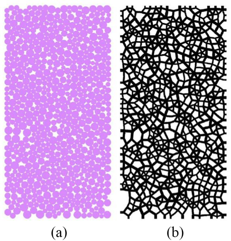
A synthetic sample of compacted particles generated by PFC2D: (a) assembly of particles which have a certain porosity, and each particle is placed in an arbitrary location and (b) contact network between particles.
In the DEM method, the standard governing equations of rigid body dynamics for pth particle (in 2D) are as follows


where m,
Parallel bond model
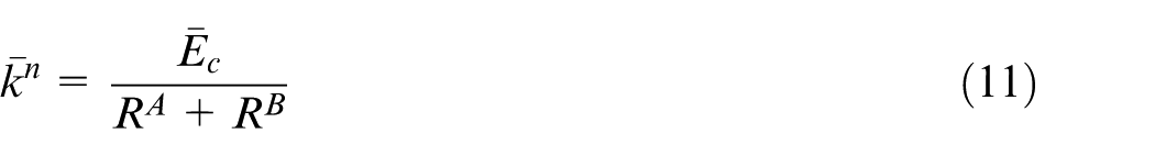
The parallel bond acts as a cement between two contacting particles. An assembly that uses the parallel bond (as a contact model) displays two types of behavior in contact zones: grain behavior and cement behavior. Figure 2 demonstrates a schematic view of the parallel bond model. The grain behavior occurs due to particles overlapping and may lead to normal and shear forces that are transmitted between contacting particles (Figure 2(a)) as follows


in which
where


in which

where
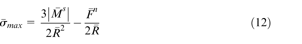
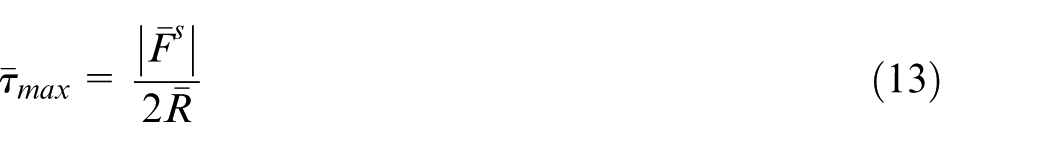
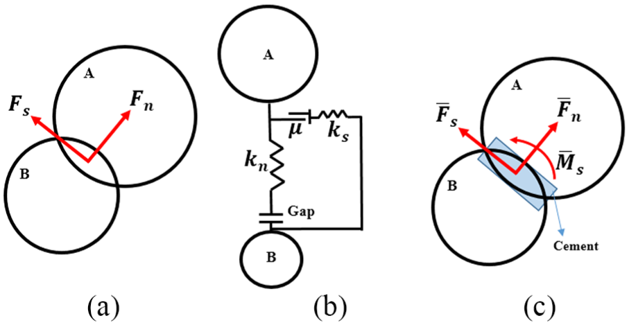
Parallel bond model: (a) schematic of grain behavior, (b) contact force model for grain behavior, and (c) schematic of cement behavior.
The parallel bond model is widely used to simulate brittle materials (e.g. ceramics), because of its ability to model brittle failure behavior and crack propagation. However, the ratio of unconfined compressive strength to tensile strength (
FJCM
Grains in BPM are round particles, while they are angular in real materials. Thus, if all bonds of a particle are broken, the rotation of this particle cannot be suppressed. The main difference between FJCM and parallel bond model is that after bond breaking, the parallel bond model has no resistance to rotation, while the FJCM can resist rotation.
30
Due to these reasons, the FJCM is a new contact model which provides
Figure 3 depicts a schematic view of the FJCM. In FJCM, each of the contacts between two contacting particles is modeled by two notional surfaces (lines in 2D) which are rigidly connected to the corresponding particles
33
(Figure 3(a)). A material with flat-joint contacts is shown in Figure 3(b). As shown in this figure, notional surfaces (while each surface has
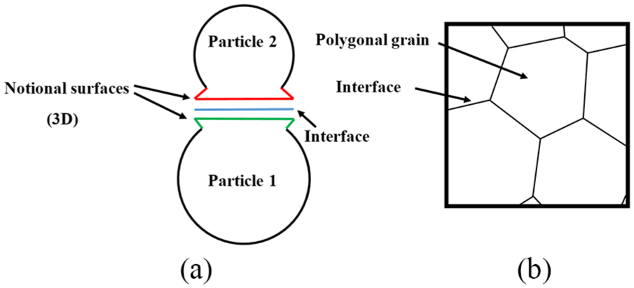
(a) Flat-joint contact and (b) material with FJCM contacts. 33
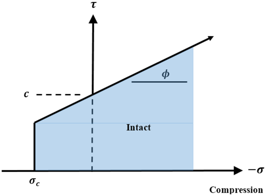
Failure envelope of a bonded flat-joint contact.
Calibration procedure for macro-properties
Adjustment of micro-parameters of the FJCM is done by performing a number of numerical calibration tests. Micro-parameters of the FJCM include
Four numerical tests employed to calibrate the model are biaxial compression test, unconfined compression test, direct tension test, and four-point bending test. These numerical tests are selected to calibrate Young’s modulus of elasticity, Poisson’s ratio, compressive strength, tensile strength, and modulus of rupture of the synthetic model. Calibration procedure should be continued until the values of these mechanical properties have insignificant deviations from the corresponding values for SCFS ceramics. In this regard, Yang
35
investigated the effects of micro-parameters on the macro-properties of the parallel bond model. He showed that Young’s modulus is mainly affected by
Biaxial compression test
Figure 5 presents schematic setup for the biaxial compression test. The test sample has a width of 1 mm and a height of 2 mm. The assembly contains 9623 particles, in which the minimum radius of particles, the maximum radius of particles, and the porosity of sample are 5 µm, 10 µm, and 13%,
29
respectively. In the biaxial test, the top platen moves toward the bottom platen with velocity
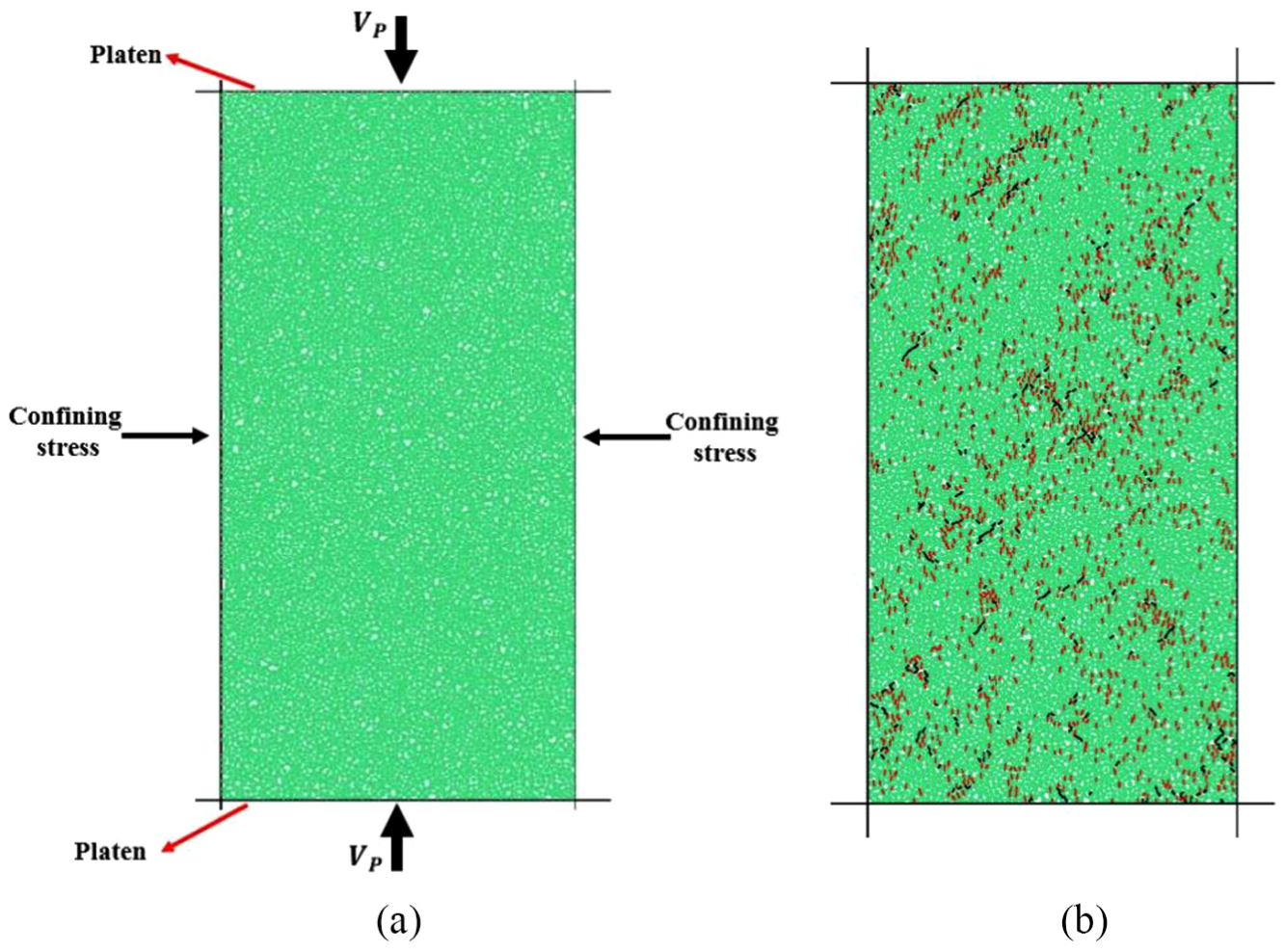
(a) Schematic setup for biaxial compression test and (b) sample under compressive load.
Unconfined compression test
Figure 6 shows the schematic setup for the unconfined compression test. The only difference between biaxial test and unconfined compression test (Figure 6(a)) is that the lateral walls are removed in the unconfined compression test (i.e. there are no confining stress and controlling servo-mechanism). Figure 6(b) depicts flat-joint material after unconfined compression loading. As observed in this figure, the dominant cause of failure of the synthetic sample (calibrated sample) is tensile cracks. Because of low tensile strength of brittle materials in comparison with shear strength of them, the number of shear cracks in the sample is much less than the number of tensile cracks. Unconfined compression test is used to calibrate compressive strength, and hence c is determined.
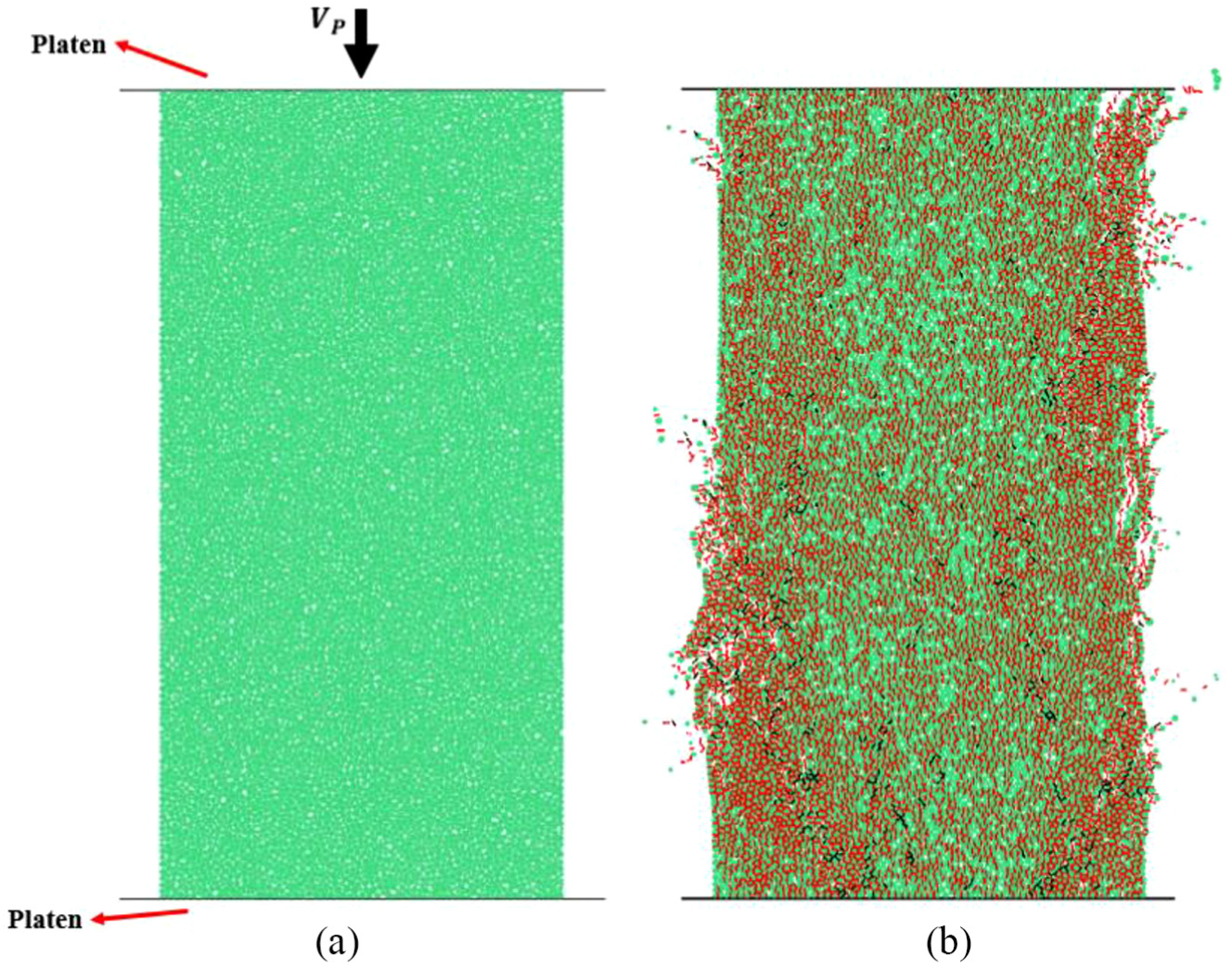
(a) Schematic setup for unconfined compression test and (b) failed sample under compressive load.
Four-point bending test
Figure 7 depicts the schematic setup for the four-point bending test and failed sample after loading. The test sample has a length of 3 mm, a height of
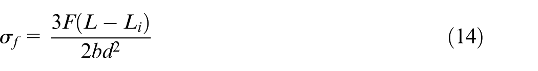
where F is the maximum force that the sample can experience before failure. Furthermore, Figure 7(b) shows that the sample is failed only by tensile cracks. The four-point bending test is applied to calibrate modulus of rupture and thus
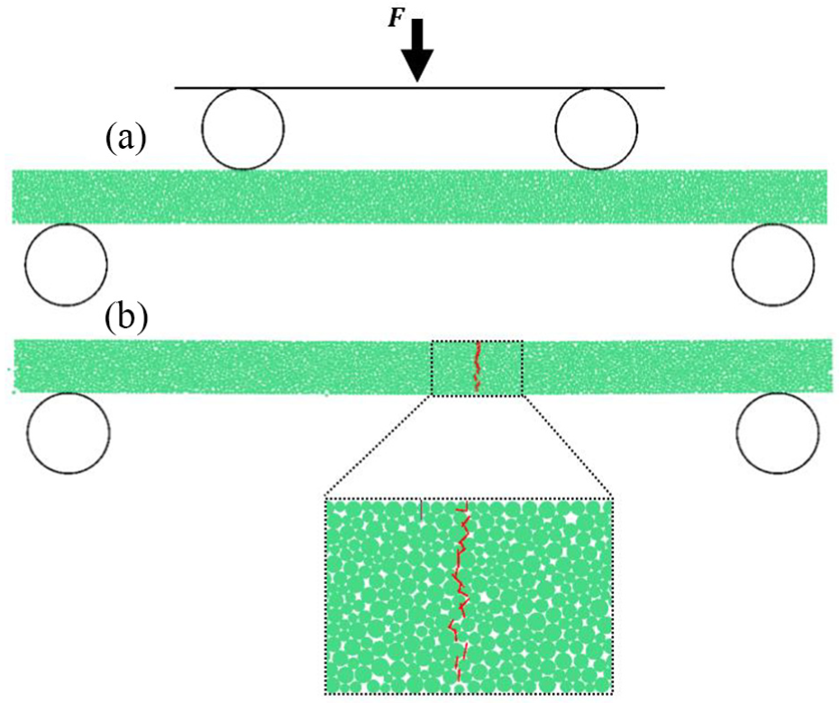
(a) Schematic setup for four-point bending test and (b) failed sample under bending load.
Direct tension test
Figure 8 shows the schematic setup for the direct tension test. The difference between unconfined compression test and direct tension test (Figure 8(a)) is that the top platens are deleted in the direct tension test. Moreover, the upper row of particles (these particles are fixed together) of the sample moves upward with velocity
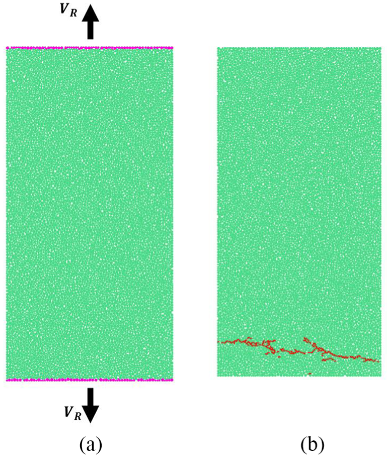
(a) Schematic setup for direct tension test and (b) failed sample under tensile load.
The values of adjusted micro-parameters of FJCM and properties of particles can be expressed as follows: (1) material properties—ρ = 2200 kg/m3,
36
Rmin = 5 µm,
34
Rmax/Rmin = 2,
34
µ = 0.2, Ec = 28.0 GPa, and kn/ks = 3.0; (2) micro-parameters of FJCM—
Comparison between mechanical properties of real SCFS ceramics and the FJCM material.
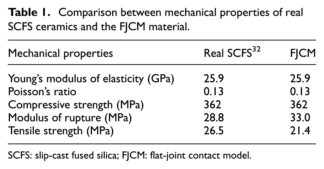
SCFS: slip-cast fused silica; FJCM: flat-joint contact model.
Experimental setup
The experimental setup for the turning process of SCFS ceramics is depicted in Figure 9. The machining operations were performed on a 1.5 hp Hardinge lathe. Cylindrical SCFS specimens with a diameter of 30.5 mm and a length of 100 mm were used. To create orthogonal cutting geometry, initial shallow grooves at an axial distance of 2.5 mm between them were machined by parting off inserts (Figure 9(b)). Material between the grooves was turned by parting off inserts which were fed in the radial direction. Thus, the machining force in the axial direction was practically zero. The alignment of the workpiece in the three-jaw chuck was performed utilizing a dial gauge. The cutting force components were measured in global directions by attaching the tool to a Kistler dynamometer of type 9257B, together with a charge amplifier of type 5070.
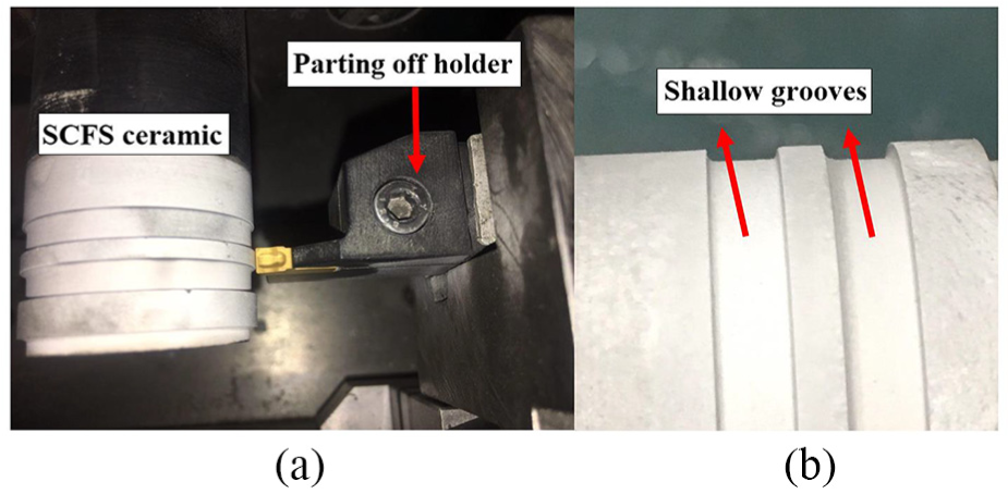
Experimental facility for the turning process of SCFS ceramics: a) cutting of the ceramic in orthogonal mode and b) Detailed view of the ceramic part.
Turning was carried out applying a SANDVIK parting off tool holder model RF151.22-2020-40 along with N151.2-400-4E 1125 inserts. Tool insert geometric parameters were as follows: rake angle of
Numerical modeling of the orthogonal cutting process
In this section, a DEM simulation of the turning process for machining of SCFS in orthogonal mode is presented. In orthogonal cutting, the cutting process is analyzed in a 2D plane strain model, where the cutting edge is perpendicular to the direction of tool–specimen relative motion. Therefore, there are no axial machining forces. When plunge mode cutting is used similar to the experimental setup described earlier, the uncut chip thickness (
A representation of equivalent orthogonal cutting and DEM model of material is shown in Figure 10. The cutter is assumed to be sharp (without cutting edge radius or a chamfer). Moreover, the tool is assumed to be ideally rigid, which is modeled by a set of three lines (i.e. walls in PFC2D). Consequently, phenomena such as tool wear and edge chipping are not considered. To make the numerical results comparable to experimental ones, the length of machining in the experiments was very small to decrease the influence of tool wear and avoid possible edge chipping. Tool–specimen friction coefficient is assumed to be 0.2 (the friction coefficient of most ceramics is in the range of 0.1–0.3). 37 The machining sample in the simulation has a width of 2 mm and a height of 1 mm, and the assembly contains 9623 particles.
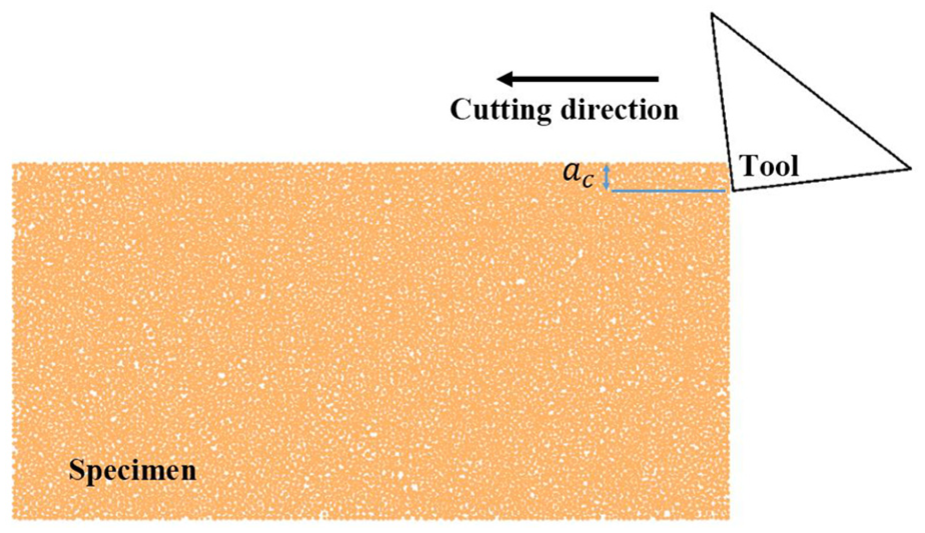
A representation of equivalent orthogonal cutting.
Results and discussion
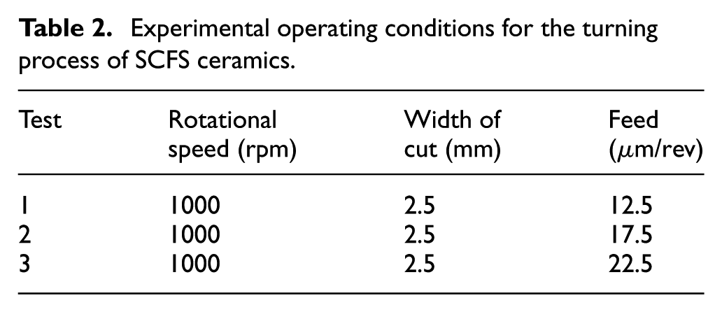
Experimental operating conditions for the turning process of SCFS ceramics are tabulated in Table 2. In all test cases, only the feed is changed and the other machining parameters are fixed. The measured machining forces (the main cutting force (
Experimental operating conditions for the turning process of SCFS ceramics.
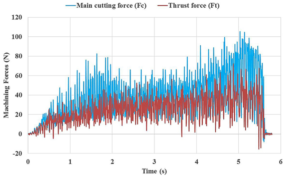
Time histories of the cutting forces from experimental measurements for test 1.
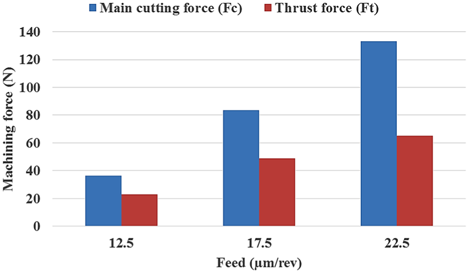
Comparison of the averaged experimental cutting forces for different feeds.
The simulation procedure is performed for the case studies of Table 2. The relative tool–specimen velocity in simulations is assumed to be equal to the experimental cutting speed, and the total simulation time is set to 1.0 ms. Figure 13 presents the simulated chip formation in the orthogonal cutting process for test 1. It is observed that when the cutting tool engages with the material and exerts force on it, micro-cracks are initiated because normal or shear stresses in FJCM contacts exceed the strength of bonds (Figure 13(b)). As the cutting tool moves forward, micro-cracks are propagated to form lateral and median macro-cracks in the specimen (Figure 13(c)). Then, the growth and coalescence of macro-cracks lead to chip formation. Furthermore, this figure shows that the cutting process of SCFS ceramics results in discontinuous chip formation as expected, and separated chips from the specimen have various sizes (Figure 13(d)). Hence, the machining of SCFS ceramics is carried out in the brittle regime. Moreover, the cutting process creates many surface/subsurface cracks and damages, and the machined surface is significantly non-smooth with peaks and valleys. In addition, more than 96% of micro-cracks are tensile cracks and only less than 4% of other micro-cracks are shear cracks.
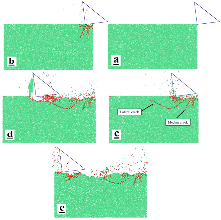
Simulated orthogonal cutting process and chip formation for test 1: (a) t = 0, (b) t = 0.1 ms, (c) t = 0.3 ms, (d) t = 0.7 ms, and (e) t = 1 ms.
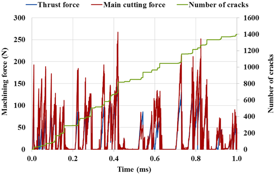
Figure 14 displays time histories of the simulated main cutting force, thrust force, and number of micro-cracks for test 1. As observed in this figure, the nature of cutting forces is dynamic. It can be found from the figure that the number of micro-cracks is increased rapidly when cutting forces rise significantly to cut large amounts of the material. Moreover, the ratio of mean values of cutting forces (i.e.
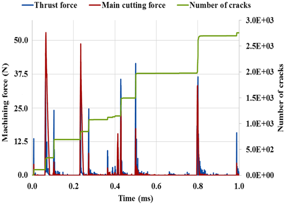
Time histories of simulated main cutting force, thrust force, and number of micro-cracks for test 1.
Updating the DEM model
As shown earlier, the lack of accuracy in estimation of machining forces may be attributed to the inadequacy of the conventional tests for determining the necessary parameters to be used in machining simulation. Among micro-parameters of FJCM contacts (
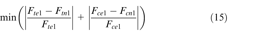
where
Time histories of simulated main cutting force, thrust force, and number of micro-cracks of updated model for test 1.
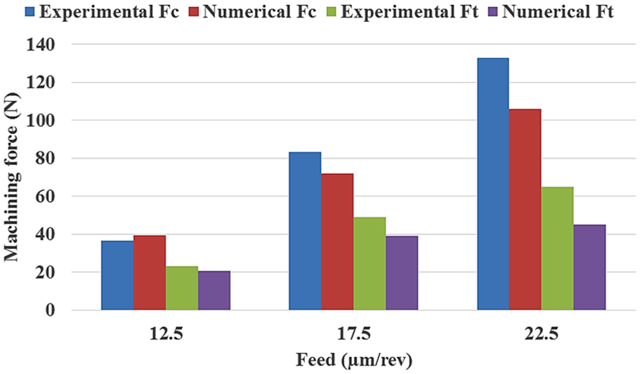
Comparison of the averaged experimental and numerical (for updated DEM model) cutting forces for different feeds.
Conclusion
In this study, mechanical modeling of machining of SCFS ceramic was carried out utilizing the DEM method and the FJCM contact model. The initiation, propagation, and coalescence of micro-cracks in the samples leading to chip formation for machining processes were modeled. In the first step, the micro-parameters of FJCM contacts were carefully adjusted using numerical calibration procedures to create a DEM model of SCFS ceramics with the same mechanical properties as the real material. However, the parameters obtained from conventional calibration tests did not produce cutting forces close to experimental results. Due to the complexity of the cutting process, the FJCM model parameters were directly updated using the cutting experiments. The comparison of results shows that predicted forces obtained based on the updated parameters are within 14%–30% of the experimentally measured forces, which is a reasonable prediction. Therefore, it is shown that the DEM model with updated parameters is a reliable model for the prediction of behavior of SCFS ceramic material in the cutting process.
Footnotes
Appendix 1
Declaration of conflicting interests
The author(s) declared no potential conflicts of interest with respect to the research, authorship, and/or publication of this article.
Funding
The author(s) disclosed receipt of the following financial support for the research, authorship, and/or publication of this article: Sharif University of Technology.