
Abstract
Due to high specific strength and strong toughness, aramid fibre–reinforced plastics have been widely used in the aircraft, military, and automobile industries. However, in the hole-making process, these excellent properties make aramid fibre–reinforced plastics difficult to machine and prone to severe entrance and exit damages. In this article, the cutting mechanisms of three typical tools (twist drill, burr tool, and brad drill) are thoroughly investigated during dry drilling of aramid fibre–reinforced plastic. On this basis, systematic experiments are conducted to evaluate the cutting performance and hole quality. At the hole entrance, the cutting edges of the twist drill peel and tear the uncut material, which results in severe fuzzing damage. Due to the radial rake angles of the burr tool and brad drill, the radial component of the cutting force can pre-tension aramid fibres prior to being cut, which effectively reduces the fuzzing defect. At the hole exit, the extrusion action of the chisel edge and the severe chip adherence are the main causes of exit damage for the twist drill and burr tool, respectively. Due to the decrease in the thrust force and improvement in the shearing action, the best hole quality is achieved by the brad drill. To further improve the hole quality, an auxiliary approach using collars is introduced to effectively restrain the damage by enhancing interfacial bonding strength. This article provides comprehensive and available information on tool performance for drilling aramid fibre–reinforced plastics, which can help guide process optimizations to achieve the desired hole quality.
Keywords
Introduction
With the ever-increasing demand for advanced composite materials, aramid fibre–reinforced plastic (AFRP) composites have been widely used in the aircraft, military, and automobile industries. 1 During the final machining processes, drilling is the pivotal process used to assemble composite components into required structures.2,3 However, due to the high toughness values and low compressive strengths of aramid fibres, AFRP composites are substantially more difficult to drill than various other fibre-reinforced plastics (FRPs). 4 Severe machining damage is induced when drilling AFRPs, which can immensely decrease the assembly accuracy and mechanical performance of a composite structure.
Some influential studies have investigated the mechanisms of drilling-induced damage in carbon fibre–reinforced plastic (CFRP) composites.5–11 The most common defects from drilling are delamination, spalling, and burrs. Hocheng et al. 6 concluded that drilling causes two different delamination mechanisms: peel-up delamination at the entrance plane and push-down delamination at the exit plane. Delamination at the entrance is caused by the peeling action of the tool, and exit delamination is induced when the thrust force exceeds the interlaminar bonding strength of a laminate.7,8 Spalling defects initiate under the action of the chisel edge and develop further due to the continuous cutting motion of the cutting edge. 9 In addition, fibres at the exit plane are pressed by the tool until the tool passes by without cutting the fibres, and thus burr defects occur at the edge of the hole exit. 10 However, current publications mainly focus on analysing the damage mechanisms in CFRP composites. The property differences between carbon and aramid fibres can result in noteworthy discrepancies in the types and mechanisms of damages experienced by CFRP and AFRP. Because the interfacial bonding strengths of AFRPs are much lower than those of CFRPs,12,13 the bonding strength of the AFRP is not sufficient to maintain the aramid fibres during drilling; therefore, drilling is prone to induce interfacial debonding and fibre pull-out in AFRPs. As a brittle material with high hardness, a carbon fibre breaks in a brittle failure mode. However, an aramid fibre is a flexible material with high toughness and low compressive strength. The majority of aramid fibres buckle under a continuous cutting motion rather than being cut by the shearing action. Therefore, the ductile fracture of an aramid fibre occurs following a certain extent of plastic deformation. The machined surfaces appear rough and fuzzy with different types of damage and morphologies, such as fuzzing at the entrance plane and tearing at the exit plane.
Extensive efforts have been made to improve hole quality during the drilling of CFRPs. The focuses of previous studies can be summarized in three aspects. The first of these was to reduce the thrust force. Feito et al. 14 conducted a comparative study on the cutting performances of a step drill and a conventional twist drill for drilling CFRP. The results showed that when using a step drill, lower thrust force and torque were observed, and delamination was reduced at low feed rates. Moreover, some experimental investigations have been made to reduce thrust force through modified tool geometries, such as optimizing the size of the chisel edge, rake angle, and point angle.15–17 The second focus was to improve critical thrust force (CTF) during the drilling process. Hocheng and Tsao 18 experimentally and numerically demonstrated the advantages of saw drills, candle stick drills, core drills, and step drills for drilling CFRP. They stressed that the CTF can be significantly improved when using special drills. Moreover, Xu et al. 19 evaluated the cutting performance of a polycrystalline diamond (PCD) twist drill and a PCD dagger drill for drilling high-strength CFRP. Their results showed that when drilling with a PCD dagger drill, the CTF was increased and the wear progression was slowed due to the beneficial role of the multi-edge. The third focus was to determine how to reverse the cutting direction and alter the point of action during drilling. Jia et al. 10 investigated the influences of the point of action and the machining direction on material removal. They noted that the upwards cutting direction was beneficial to inhibit defects. Based on the geometrical analysis, they presented a new structure, namely, an intermittent-sawtooth drill, to enable upwards cutting.
While high-quality drilling of CFRP composites can be achieved through the aforementioned methods, a number of different problems arise when drilling AFRP composites. Won and Dharan 20 investigated the machined surfaces of AFRPs and CFRPs when drilling with carbide-tipped twist drills under the optimal cutting parameters of each material. The results showed that the CFRPs exhibited relatively smooth machined surfaces. However, the machined surfaces of the AFRPs were poor and fuzzy with a large degree of fibre pull-out and crushed aramid fibre bundles, which clogged the hole and decreased the dimensional accuracy. It can be concluded that the cutting performances of cutters and the effects of cutting parameters on the hole quality in AFRPs are very different from those for CFRPs due to the different properties and damage mechanisms of the fibres. Therefore, the mechanisms of action between the cutting edges of different tools and composites composed of aramid fibres cannot be accurately described by the current literature. Until now, studies on cutting mechanism analysis and tool performance evaluation for drilling AFRPs have been very limited and rarely found; however, such studies are essential to better understand these phenomena.
In this article, the cutting mechanisms of three typical tools (twist drill, brad drill, and burr tool) during the drilling of AFRPs are thoroughly investigated. To further improve the hole quality, an auxiliary approach using collars is proposed. A pair of collars is fixed at the upper and lower planes of the laminate. The tool moves across the holes in the collars to prevent additional tool wear. On this basis, the inhibition mechanisms are geometrically analysed. Systematic experiments are conducted to reveal the influences of different tools, cutting parameters, and collars on the thrust force and hole quality. Furthermore, the AFRP cutting behaviours of different tool geometries are analysed on a microscopic scale.
Experimentation
Fabrication of AFRP laminates
AFRP laminates are fabricated using plain-weave aramid/epoxy prepregs with fibre volume fractions of 60%. The laminates consist of 15 layers with fibre orientations [0°]15 and are cured in an autoclave at 115 °C for 60 min followed by 180 °C for 120 min. After curing, the laminates are cut into specimens of 160 mm × 100 mm with 4.0 mm thickness prior to drilling.
Drilling experiment design
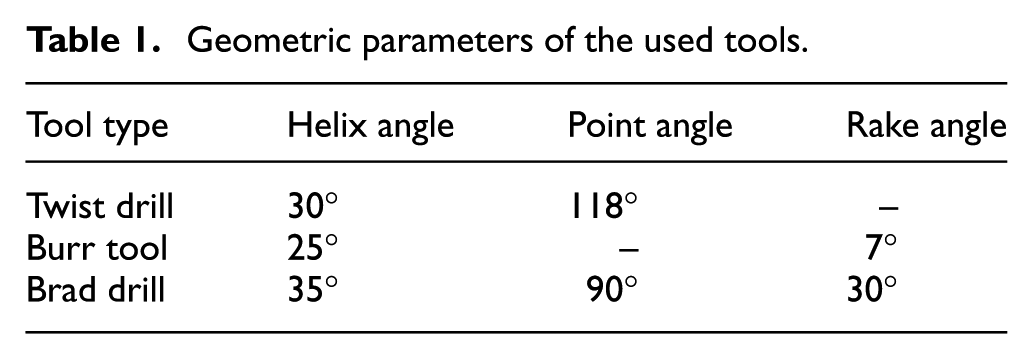
Figure 1(a) illustrates a schematic diagram of the experimental devices. The drilling operations are carried out on a Computer Numerical Control (CNC) machine tool. As shown in Figure 1(b), three types of uncoated solid carbide tools with 6.0 mm diameters are used. The geometric parameters of the cutting tools are listed in Table 1. As the most commonly used drilling tool, a standard twist drill with a point angle of 118° and a chisel edge length of 1.7 mm is chosen as the benchmark for the comparisons in this article. The second drilling tool is a burr tool with multiple helical edges and two frontal cutting edges. Due to the special geometrical design, the burr tool may help shear aramid fibres at the entrance plane and restrict the fuzzing defect. The multiple helical edges may repeatedly trim the machined surface to improve the hole quality. Therefore, exploratory research on the cutting performance of burr tools in drilling AFRP is conducted in this study. The third tool is a brad drill with a 35° helix angle. On the cross-section, both the axial rake angle and the radial rake angle are 30°. Compared with the standard twist drill, the brad drill has a shorter chisel edge, which may reduce the thrust force and subsequently reduce delamination damage. Moreover, the modified main cutting edges may promote shear fracture in the aramid fibres.
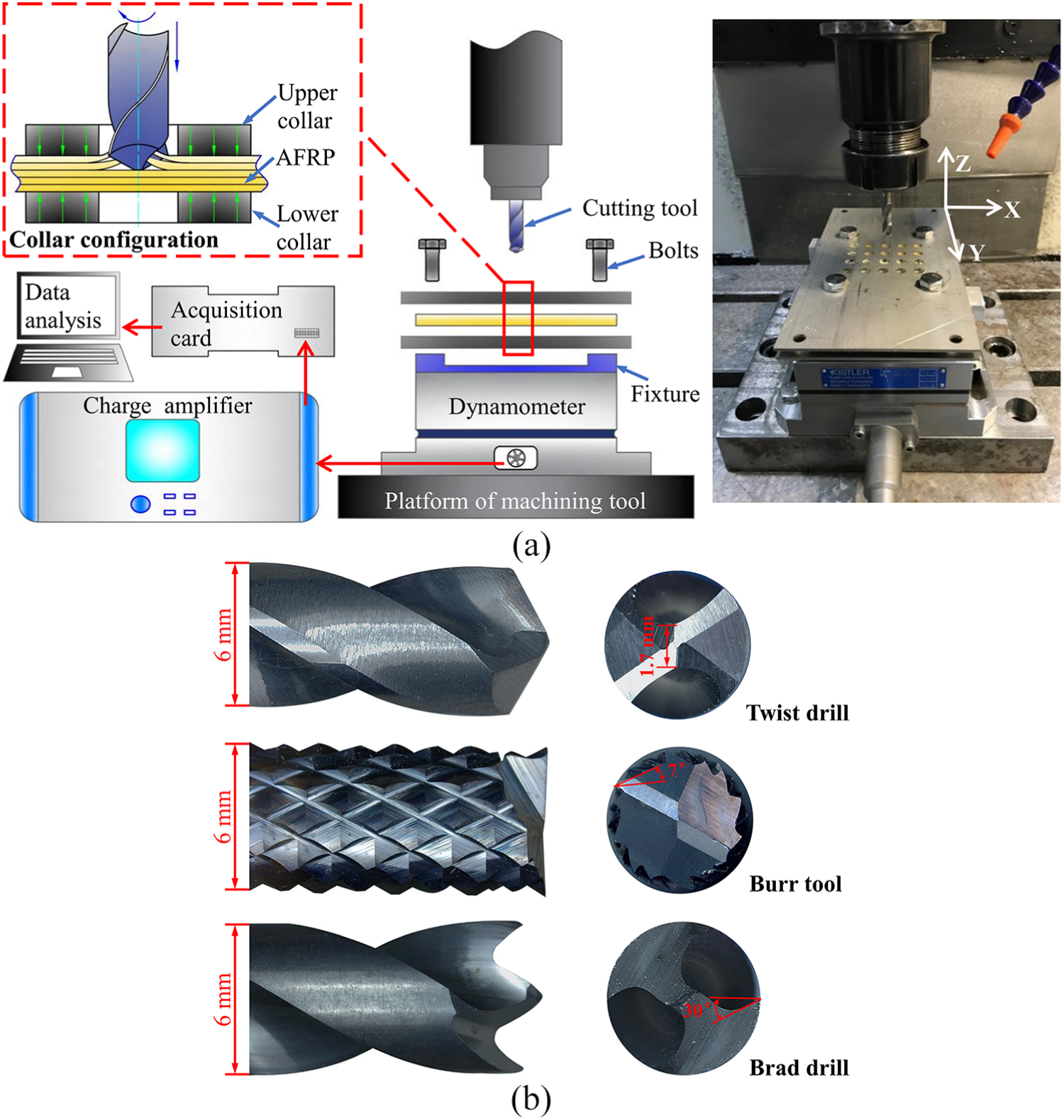
Experimental details for AFRP drilling: (a) experimental devices and (b) scheme of typical tools.
Geometric parameters of the used tools.
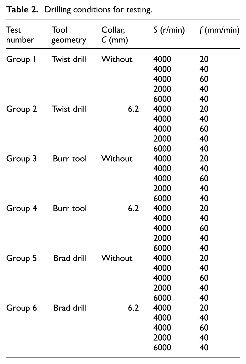
To achieve the collar configuration, a pair of 2 mm thick stainless steel plates with prefabricated holes is fixed on the upper and lower surfaces of the laminate. To prevent cutting the collars, the inner diameter of the collar is 6.2 mm, which is slightly larger than the cutter diameter. When drilling without the collars, the workpiece is directly installed on the fixture. The drilling conditions are summarized in Table 2. The preliminary tests show that the experimental results of each test agree with the repeatability tests, so in this article, each group of cutting parameters is performed only once. To avoid the influences of tool wear on the thrust force and hole quality, each new drill is utilized for drilling only two holes. Due to the hygroscopicity of AFRP laminates, drilling processes are performed in dry cutting conditions.
Drilling conditions for testing.
Measurements and evaluation
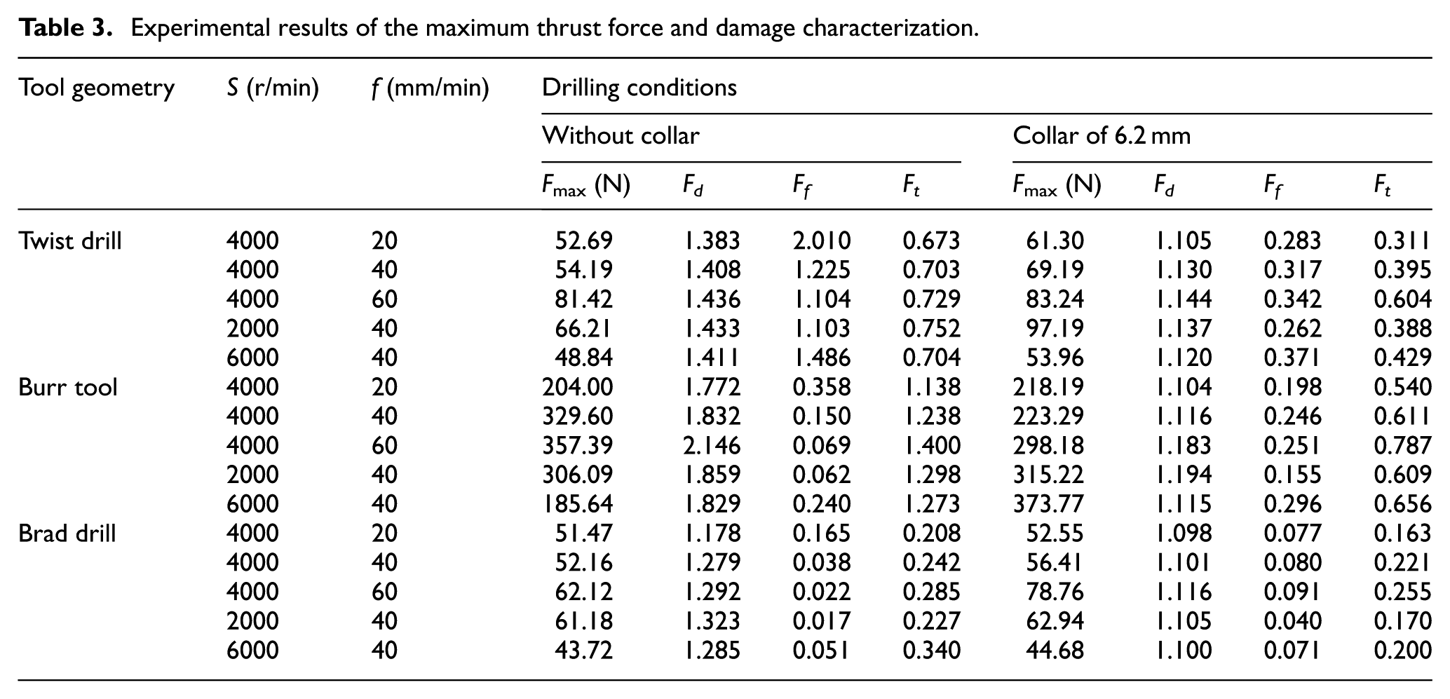
As shown in Figure 1(a), to measure the dynamic thrust force during drilling, a dynamometer (9257B, Kistler) is connected to a 5070A charge amplifier and a data acquisition card. The cutting force data are processed by Dynoware software. The experimental values of the maximum thrust force
Experimental results of the maximum thrust force and damage characterization.
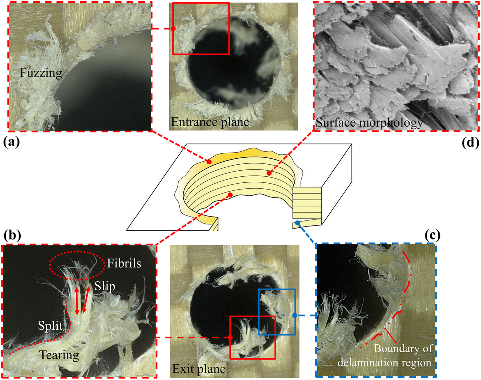
Evaluation methodology of drilled hole: (a) morphology of fuzzing defect, (b) morphology of tearing defect, (c) morphology of delamination defect, and (d) surface morphology in the hole wall.
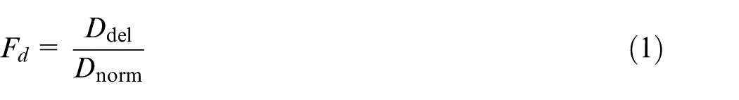
The delamination factor is used to characterize the delamination defects in this article. Figure 3(a) shows the image of the exit plane for the twist drill when drilling without collars under the following conditions: S = 2000 r/min and f = 40 mm/min. The delamination factor
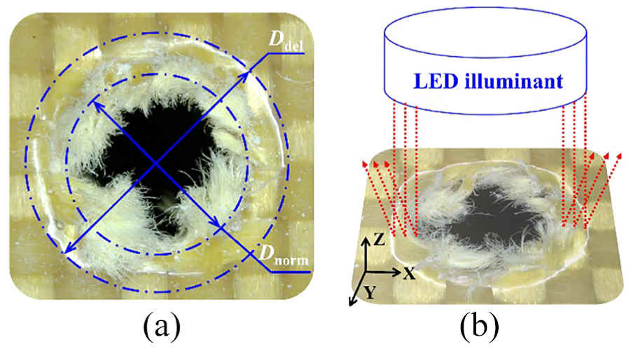
Characterization of delamination defect: (a) definition of delamination factor and (b) the measurement method of delamination.
Ultrasonic C-scan inspection is one of the most commonly used nondestructive methods for measuring delamination defects. 23 A relatively smooth machined surface is observed after drilling a CFRP, which is suitable for an ultrasonic C-scan. However, the poor and fuzzy machined surface of an AFRP significantly decreases the accuracy of measurement results provided by an ultrasonic C-scan inspection. First, the pull-out fibres and the crushed aramid fibre bundles at the entrance and exit planes severely affect the ultrasound transmission, which makes the edge of the drilled hole in the generated image very blurry; this blurriness makes it difficult to accurately determine the boundary of the delamination region. Second, because the crushed aramid fibre bundles clogged the hole, the blurry outline presented by the ultrasonic C-scan may be mixed with fuzzing and tearing damages. Therefore, an alternative approach for measuring the size of a delamination is proposed in this article. As illustrated in Figure 3(b), an LED illuminant is fixed upon the workpiece to illuminate the surface around the hole. The delamination region swells when pushed down, so the bright white profile with high reflection will be the boundary of the delamination region. Based on the visual observation, the outermost edge of the white profile can be measured with the measuring software of the digital microscope.
A fuzzing factor
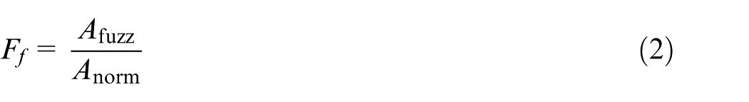
where
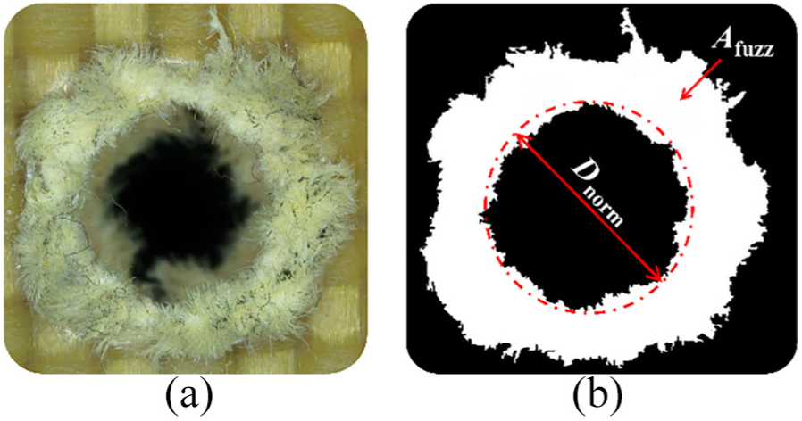
Characterization of fuzzing defect: (a) the digital image of hole entrance and (b) the transformational binary picture.
Figure 5(a) shows an image of the exit plane when drilling with the brad drill without collars under a spindle speed of 4000 r/min and a feed rate of 60 mm/min. As illustrated in Figure 5(b), the tearing factor
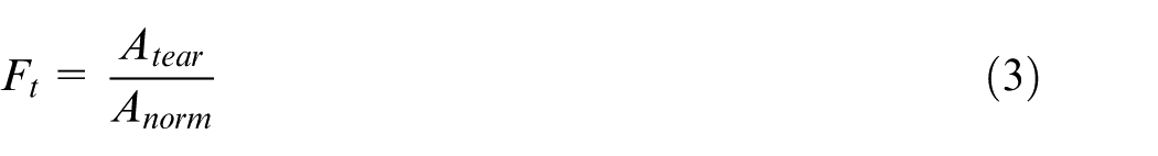
Characterization of tearing defect: (a) the digital image of hole exit and (b) the transformational binary picture.
Geometrical characteristics and mechanisms of action
Twist drill
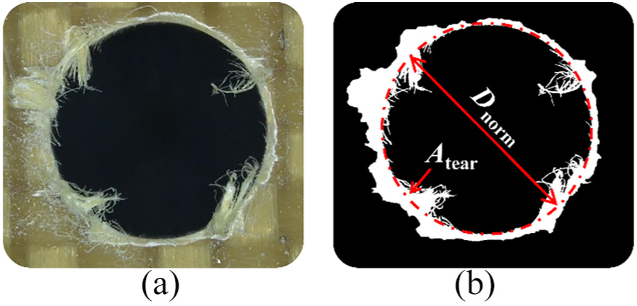
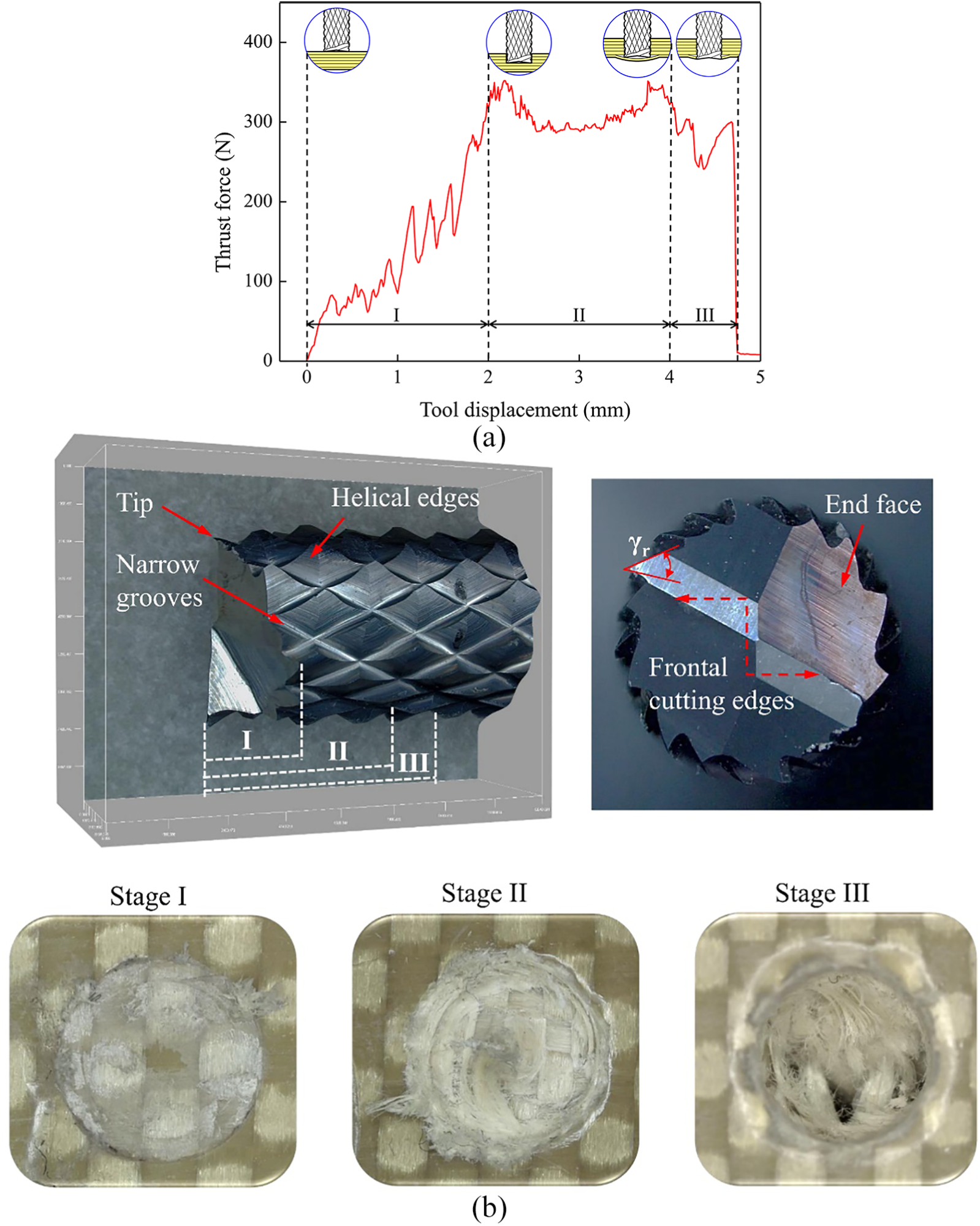
To investigate the mechanism of action between the cutting edges and fibres, the geometrical characteristics of the tool and morphologies of the hole entrance are related to the thrust force of different drilling stages. As shown in Figure 6(a), the thrust force curve of the twist drill can be divided into three stages within each drilling cycle. The cutting edges of the twist drill involved in each stage and the corresponding entrance morphologies are shown in Figure 6(b).
Drilling process of twist drill: (a) thrust force curve over one drilling cycle (f = 40 mm/min, S = 4000 r/min, without collars) and (b) cutting edges involved in each stage and the corresponding entrance morphologies.
In stage I, the thrust force increases rapidly when the chisel edge enters into the entrance plane, and then the main cutting edges are involved in machining. The span of stage I is the height of the drill tip. Moreover, as seen in the entrance morphology of stage I, the surface machined by the chisel edge is very rough due to the negative rake angle of the chisel edge. Stage II initiates from the full engagement of the cutting edges, which generates the maximum thrust force during drilling. Under a continuous cutting motion, the laminate stiffness decreases because of the thickness decrease in the uncut material and the increase in machining temperature. Therefore, the thrust force gradually decreases. As shown in the image of stage II, due to the geometric configurations of the main cutting edges, material removal is in the shape of an inverted cone. Because of the properties of aramid fibres, the majority of the materials cannot be neatly cut, and the residual materials accumulate in a helical trajectory. Although the fuzzy surface of the hole wall would be removed under a continuous cutting motion, the fuzzing defect at the entrance propagates to a greater extent. Stage III initiates when the chisel edge breaks through the exit plane of the laminate. The thrust force decreases rapidly until the entirety of the main cutting edges penetrates the laminate (the thrust force decreases to approximately 0). The image of stage III shows a diamond-shaped tearing gap on the exit layer that corresponds with the shape of the chisel edge. This phenomenon can be explained by the cutting mechanism of the chisel edge. Due to the negative rake angle
Burr tool
Figure 7(a) illustrates a typical thrust force curve of a burr tool within a drilling cycle. The thrust force curve is divided into three stages. The cutting edges of the burr tool involved in each stage and the corresponding entrance morphologies are shown in Figure 7(b). The figure shows that the frontal cutting edges are located across the end-face, and multiple diamond-shaped cutting units are helically located on the tool. Stage I exhibits a rapid increase in thrust force when the frontal cutting edges contact the entrance plane. In the span of stage I (approximately equal to the height of the end-face), alternant peaks and valleys in the thrust force can be observed. This phenomenon is related to the structure of the AFRP laminate, which is manufactured layer-by-layer. When frontal cutting edges enter a new layer, the thrust force increases with increasing of uncut-chip area.
24
With the decreasing thickness of this layer, a valley in the thrust force occurs due to a decrease in stiffness. In addition, due to the radial rake angle
Drilling process of burr tool: (a) thrust force curve over one drilling cycle (f = 40 mm/min, S = 4000 r/min, without collars) and (b) cutting edges involved in each stage and the corresponding entrance morphologies.
Stage II initiates from the entire end-face entering the laminate, which results in the maximum thrust force. The heat accumulated around the cutting edges leads to a decrease in the laminate stiffness, so the thrust force decreases after reaching the maximum value. However, the thrust force gradually increases again when the tool displacement increases to approximately 3.0 mm. To explain this phenomenon, a detailed analysis of stage II is illustrated in Figure 8(a). Note that the machining mechanism of a burr tool is similar to grinding. 25 The main function of the helical edges is to generate the surface of the hole wall and trim the edge of the hole. The material cutting is mainly executed by the two frontal cutting edges. The slope of the end-face plays an important role in chip evacuation. However, because of insufficient space for chip removal, the narrow grooves on the helical edges cause difficulty in chip evacuation when the entire end-face enters the laminate (tool displacement > 2.0 mm). In addition, unlike the powder-like chips produced when drilling CFRPs, the flocculent chips produced when drilling AFRPs are prone to clog the narrow grooves and then wrap the helical edges as drilling proceeds. Therefore, the thrust force is gradually increased. It can be suggested that the thickness of the workpiece should be less than the height of the end-face when dry drilling AFRP laminates with a burr tool.
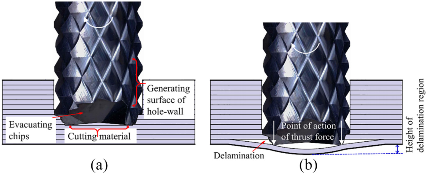
Detail analysis of drilling process: (a) actions of different components in stage II and (b) drilling-induced exit damage in stage III.
In stage III, another noteworthy valley in the thrust force can be observed, which is caused by severe exit delamination. As shown in Figure 8(b), because the supporting action of the uncut material significantly decreases with the decrease in the uncut thickness, delamination occurs at some point when the thrust force exceeds the interlaminar bonding strength. Due to the geometrical configuration of the burr tool, a much higher thrust force is generated during drilling. In addition, the point of action of the thrust force is the tip of the frontal cutting edge, which is located at the outermost edge of the tool diameter. Therefore, more severe delamination occurs and thus exceeds the normal diameter of the hole. Because the formation of delamination leads to obvious swelling at the exit plane, the final tool displacement is larger than the laminate thickness of 4 mm.
Brad drill
A typical thrust force curve of a brad drill within a drilling cycle is shown in Figure 9(a). The thrust force as a function of tool displacement can be divided into four stages. Figure 9(b) illustrates the cutting edges involved in each stage and the corresponding entrance morphologies. The figure shows that the drill tip of the brad drill is modified into a shorter chisel edge with a length of 0.4 mm and two straight cutting edges with a point angle of 90°. The C-shaped main cutting edge is the key feature of a brad drill. The chip breaker groove is connected with the main cutting edge. In stage I, the thrust force increases rapidly when the chisel edge enters the laminate. Stage II initiates from the tips of the main cutting edges penetrating the entrance plane. Due to the positive radial rake angle
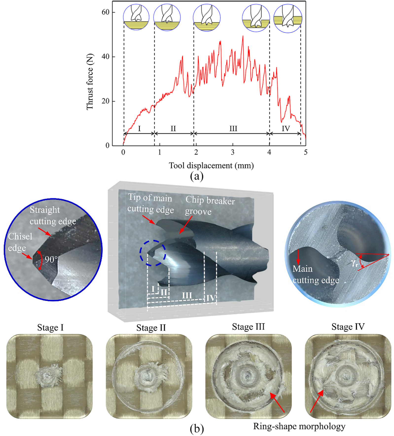
Drilling process of brad drill: (a) thrust force curve over one drilling cycle (f = 40 mm/min, S = 4000 r/min, without collars) and (b) cutting edges involved in each stage and the corresponding entrance morphologies.
Stage III starts from the point when the entirely of the main cutting edges is involved in machining. The thrust force significantly fluctuates with alternating peaks and valleys. To explain this phenomenon, a schematic diagram of the drilling process in stage III is shown in Figure 10(a). The chisel edge and straight cutting edges are beneficial for drilling centring to obtain a stable process in high-speed drilling. The cutting action is mainly conducted by the main cutting edges. In addition, the chip breaker groove facilitates chip breaking and chip evacuation. Due to the concave main cutting edges, a ring-shaped morphology is formed under the main cutting edges. Because the laminate is manufactured layer-by-layer, chips of the ring-shaped morphology are intermittently removed. Therefore, the repetitive variations in the stiffness of each layer lead to obvious fluctuations in the thrust force. In addition, the thrust force exhibits a decreasing trend in stage IV, which initiates from the chisel edge penetrating the exit plane. However, the thrust force does not decrease to approximately 0 when the tool drills out. As illustrated in Figure 10(b), this phenomenon can be attributed to the specific damage induced by the brad drill. When drilling to the exit plane, the main cutting edges first cut the outermost edge of the uncut material. Due to the lack of supporting action at the hole exit, the residual material bends under the cutting motion. As a result, the residual material cannot be thoroughly cut and is still connected to the exit plane. Because the residual material clogs the hole, the thrust force at the last segment does not decrease to 0.
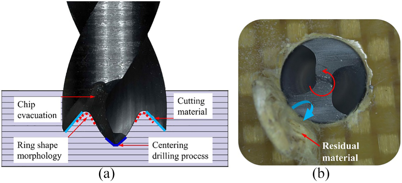
Detail analysis of drilling process: (a) actions of different components in stage III and (b) the specific exit damage introduced by brad drill in stage IV.
Inhibiting drilling-induced damage
In summary, the application of special tool geometries when drilling AFRPs can improve hole quality to some extent. However, other defects are introduced by special tools. To further improve the hole quality for AFRP laminates, an auxiliary approach using collars is proposed, and the inhibition mechanisms are analysed as follows.
As shown in Figure 11(a), when the tool enters the laminate, uncut material at the entrance plane is torn and pulled under the peeling action of the drill. Figure 11(b) illustrates a simplified orthogonal cutting model at the hole entrance. When drilling without collars, the strength of resisting peel-up is mainly dependent on the interfacial bonding strength between the fibres and matrix. Because the bonding strength of an AFRP is much lower than CFRP, severe interfacial debonding is prone to be induced. In this situation, an aramid fibre is slid and deformed under the action of the tool, which causes obvious yielding and necking after a certain extent of plastic deformation. When drilling with collars, the uncut material at the entrance plane bears a compressive force
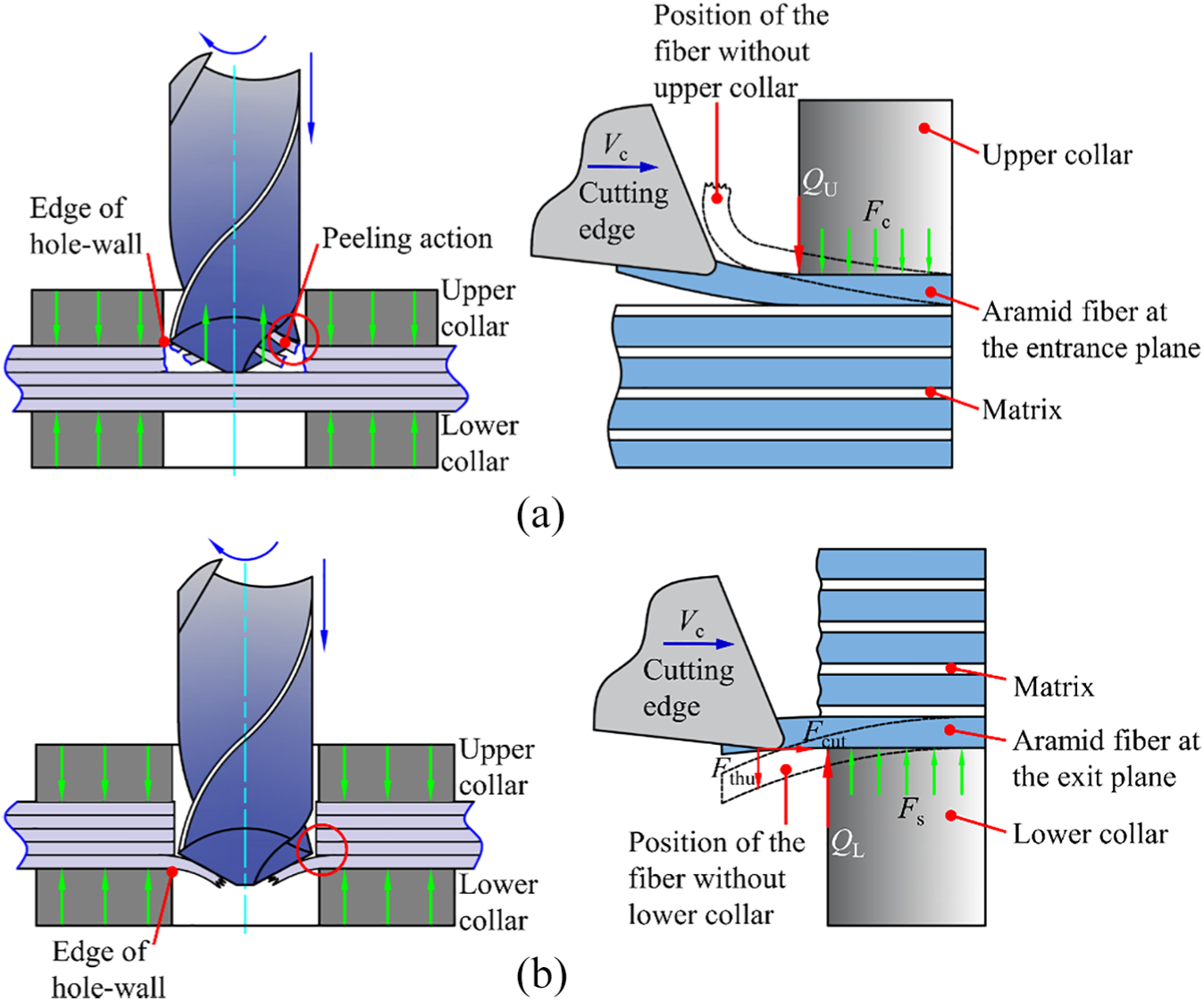
Schematic diagram of inhibiting damages: (a) fuzzing defect, (b) cutting model at the hole entrance, (c) tearing defect, and (d) cutting model at the exit plane.
To analyse the inhibition mechanisms of exit damage, a simplified orthogonal cutting model at the exit plane is illustrated in Figure 11(d). Under the action of the cutting edge, an aramid fibre is subjected to a cutting force
In addition, tearing defects are the second type of exit damage observed when drilling AFRPs. As shown in Figure 11(c), the uncut fibres are bent and twisted under the action of the thrust force and torque when drilling to the exit plane. Consequently, tearing defects are likely to be created. In the case of drilling with collars, the interfacial bonding strength is improved under the supporting action of
Results and discussion
Thrust force
As discussed in the ‘Geometrical characteristics and mechanisms of action’ section, the variation trends in the thrust force are different among the different tools and drilling stages. Therefore, we extract the maximum thrust force
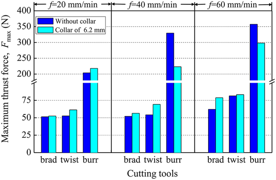
Influences of the cutting tools
A comparison of the maximum thrust forces observed by using the different tools at a spindle speed of 4000 r/min is shown in Figure 12. The results show that the brad drill generates the lowest thrust force, whereas the burr tool generates the highest thrust force under an arbitrary feed rate. When drilling with the twist drill, the last layer of the laminate is extruded by the chisel edge due to the negative rake angle. Consequently, the thrust force exerted from the chisel edge is the main component of the total thrust force. Because a shorter chisel edge is modified at the drill tip, the thrust force can be effectively reduced when utilizing a brad drill. In contrast, due to the frontal cutting edges located across the end-face, the highest thrust force is generated by the burr tool.
Effects of different tools on the maximum thrust force.
Influences of the collars
As shown in Figure 12, the thrust forces when drilling with collars are higher than those when drilling without collars for both the twist drill and brad drill. The stiffness of the process system k can be expressed by k = F/Z, where F is the thrust force and Z is the corresponding displacement. Due to the supporting action of collars, k is increased. Therefore, when the tool moves with the same displacement during drilling (equal to the height of the drill tip plus the thickness of the laminate), the required thrust force increases as the stiffness of the process system increases. However, irregular thrust force results can be observed when drilling with a burr tool. The colour of the hole wall after drilling an AFRP can characterize the extent of the thermal degradation of the matrix, which is closely related to the cutting temperature. As shown in Figure 13, the colour of the hole wall drilled by the burr tool is much darker than that of the other two drills under the same cutting parameters. Therefore, we can indirectly draw the conclusion that the heat accumulated when using the burr tool is higher than that for the other two drills. Moreover, because the collars are fixed on the upper and lower surfaces of the laminate, heat exchange between the workpiece and ambient air is restricted to a certain extent. The cutting temperature would be sufficient to soften the matrices of AFRP laminates. Therefore, the combined effect of increasing the stiffness of the process system and the softened matrix may result in irregular results when utilizing a burr tool.
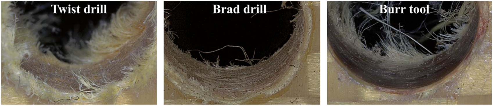
Thermal damage in the hole wall drilled by different tools (f = 40 mm/min, S = 4000 r/min).
Influence of the feed rate
Figure 14 shows the influence of the feed rate on the maximum thrust force when S = 4000 r/min. The results show that the thrust force increases with increasing feed rate. This phenomenon can be attributed to two factors. First, both the undeformed chip thickness and the corresponding machining resistance increase with increasing feed speed. Second, the heat accumulated from cutting during drilling increases in proportion to the square root of machining time. 26 When drilling at a low feed rate, the softened matrix causes a decrease in the thrust force. Therefore, the thrust force increases with increasing feed rate. In addition, when using the twist drill and brad drill without collars, the growth rate of the maximum thrust force is relatively small when the feed rate increases from 20 to 40 mm/min. This behaviour can be discussed in two aspects. Considering the average thrust force of the twist drill in stage II and the average thrust force of the brad drill in stage III (i.e. when the whole main cutting edges are involved in machining), the average values are increased by 15.4% and 14.2%, respectively, when the feed rate varies from 20 to 40 mm/min. Furthermore, as explained in the literature,3,27 the thrust force is not proportional to the thickness of the undeformed chip, which is reported as a function of feed rate. Because the ploughing force becomes a smaller portion of the total cutting force when drilling at an increased feed rate, a decrease in the specific cutting energy can be induced to generate a slight increase in the thrust force.
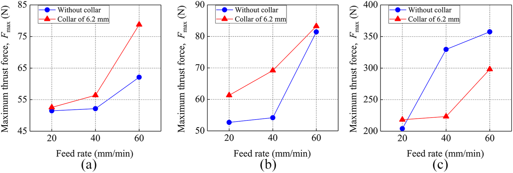
Effects of feed rate on the maximum thrust force: (a) brad drill, (b) twist drill, and (c) burr tool.
Influence of the spindle speed
As illustrated in Figure 15, the thrust force decreases with increasing spindle speed during drilling for both the twist drill and brad drill. This behaviour may be because the high cutting speed (V = πDS) results in a high machining temperature and softened matrices in the laminates. Therefore, increasing the spindle speed would favour a relatively low thrust force when drilling an AFRP. However, there are irregular trends when utilizing burr tool. Many narrow grooves between the intermittent helical edges cause insufficient space for chip evacuation. In addition, unlike the powder-like chips from CFRP laminates, the flocculent chips from AFRP laminates are prone to clog the narrow grooves and wrap the helical edges as the drilling proceeds. Accordingly, the cutting action of the burr tool turns into a punching action when drilling to the exit plane. Due to the interference of the severe chip adherence when drilling with the burr tool, no regular trend can be observed to demonstrate the influence of the spindle speed on the thrust force.
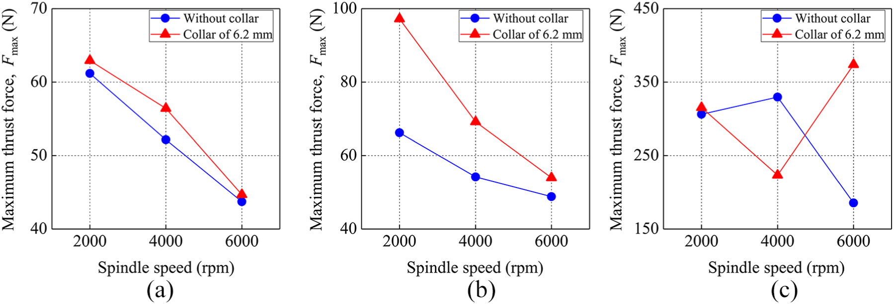
Effects of spindle speed on the maximum thrust force: (a) brad drill, (b) twist drill, and (c) burr tool.
Damage analysis at the entrance and exit plane
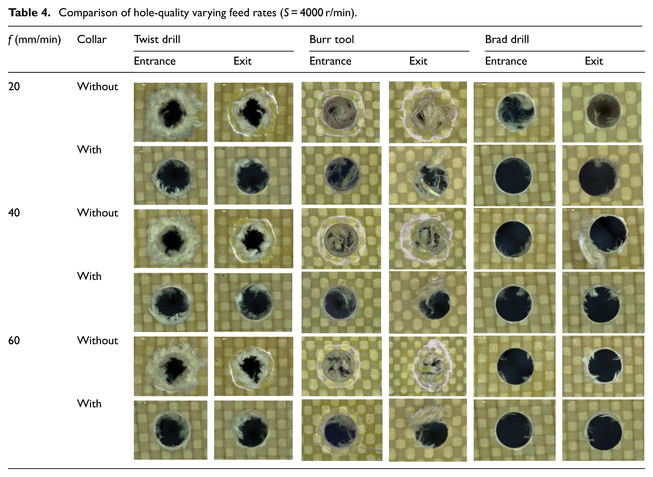
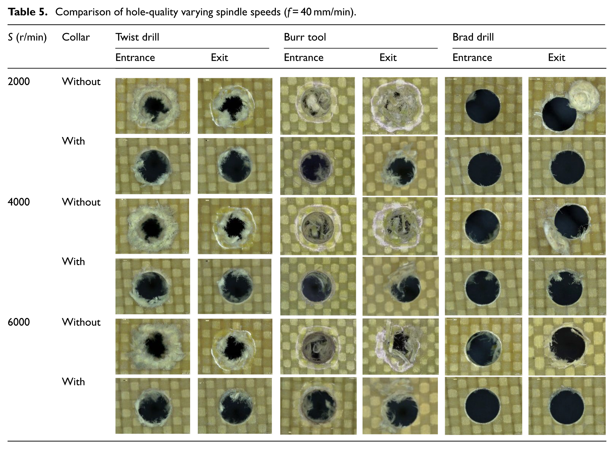
Tables 4 and 5 present images of the hole quality at the entrance and exit planes under different drilling conditions. Different degrees of damage can be clearly observed with varying feed rates and spindle speeds. Based on the measurement and evaluation methods discussed in the ‘Measurements and evaluation’ section, the quantitative analyses of delamination, fuzzing, and tearing defects are discussed as follows.
Comparison of hole-quality varying feed rates (S = 4000 r/min).
Comparison of hole-quality varying spindle speeds (f = 40 mm/min).
Influences of the cutting tools
There is a clear correlation between the thrust force and delamination. Compared with the aforementioned analysis in the ‘Influences of the cutting tools’ section, a similar variation trend in the delamination defects can be observed in Figure 16(a). The brad drill generates the lowest delamination factor while the burr tool induces the highest delamination factor under a spindle speed of 4000 r/min. Using the twist drill as a basis, when drilling without collars at feed rates from 20 to 60 mm/min,
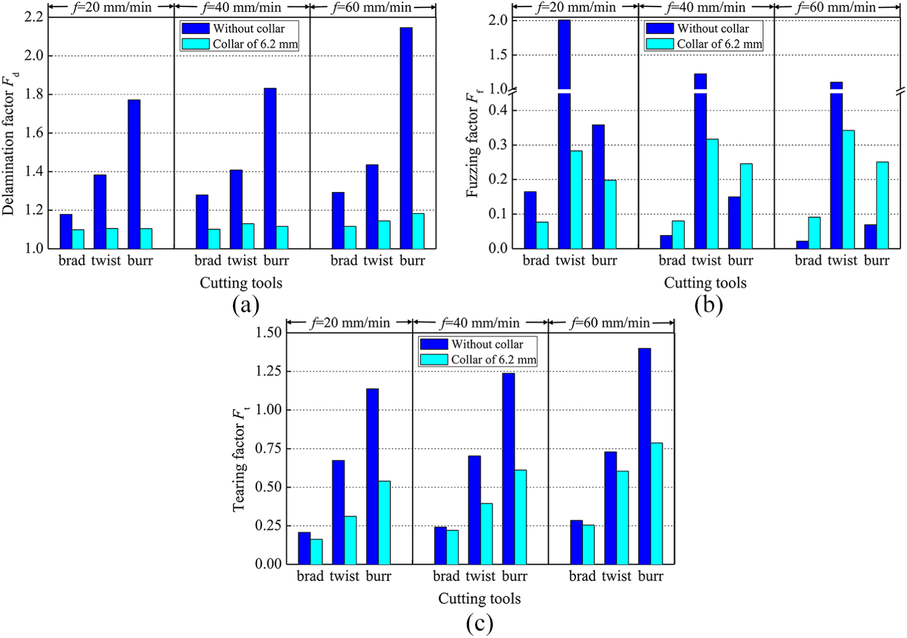
Effects of different tools and collars (S = 4000 r/min): (a) delamination, (b) fuzzing, and (c) tearing.
The influences of different cutting tools on the fuzzing factor are illustrated in Figure 16(b). As discussed in sections ‘Burr tool’ and ‘Brad drill’, the fuzzing defect can be effectively decreased when utilizing the burr tool and brad drill. Compared with the results for the twist drill,
Figure 16(c) illustrates a comparison of the tearing defects when S = 4000 r/min. Compared with the results of the twist drill when drilling without collars at feed rates from 20 to 60 mm/min,
Influence of the collars
Figure 16 also illustrates the influence of the collars on the drilling-induced damage. As shown in Figure 16(a), using the results of f = 20 mm/min as an example, the collars decrease
In addition, as shown in Figure 16(c), the collars also have a significant effect on the tearing defects. Because similar trends can be observed for the different tools, the results of the brad drill are discussed as an example. Compared with the
Influence of the feed rate
The influence of the feed rate on drilling-induced damage at a spindle speed of 4000 r/min are shown in Figure 17. The results show that
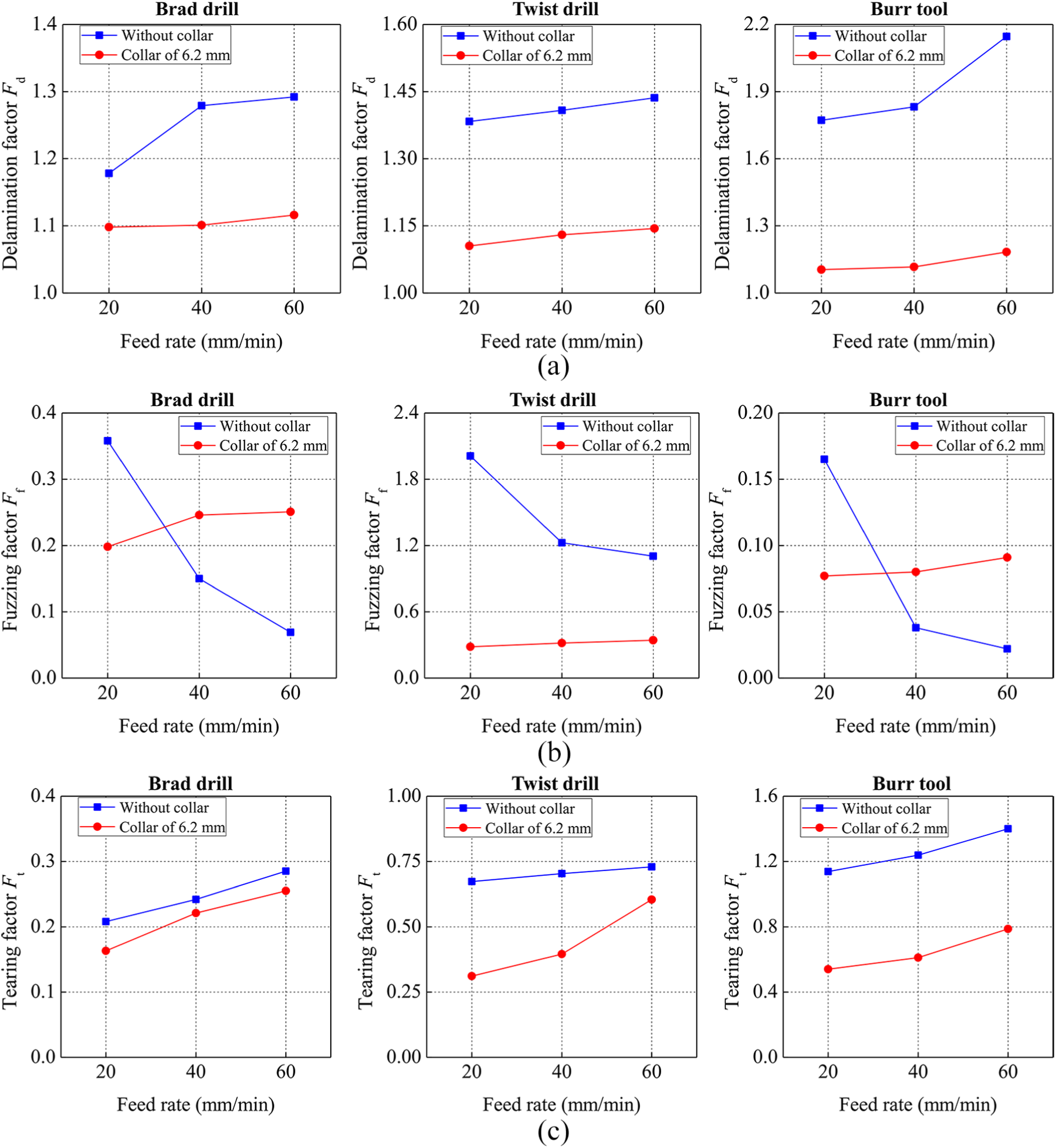
Effects of feed rate: (a) delamination, (b) fuzzing, and (c) tearing.
Influence of the spindle speed
Figure 18(a) illustrates the influence of the spindle speed on the delamination defect when f = 40 mm/min. As discussed in the ‘Influence of the spindle speed’ section, increasing the spindle speed would favour a relatively low thrust force. Because the thrust force is the driving element behind the formation of delamination,
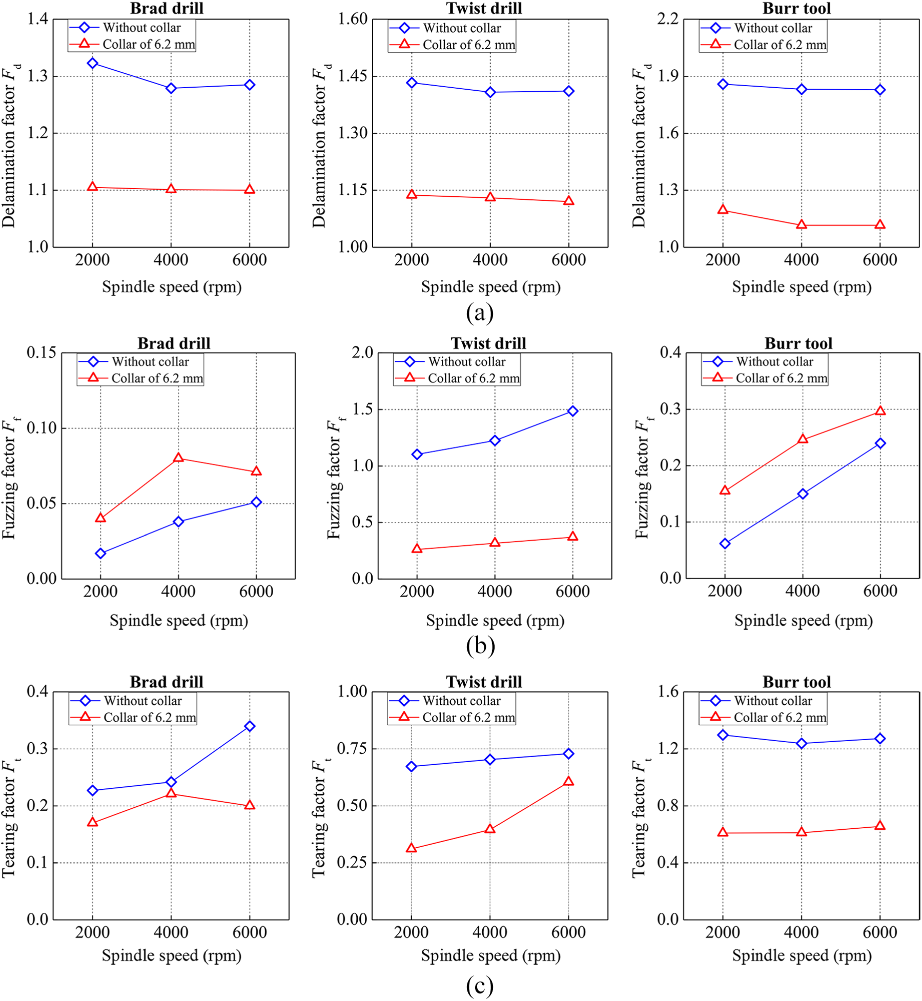
Effects of spindle speed: (a) delamination, (b) fuzzing, and (c) tearing.
Surface morphologies
As shown in Figure 19(a), the workpiece is cut along the cross-section. θ is used to characterize the angle between the cutting direction and fibre orientation. Therefore, the weft and warp fibre bundles are oriented at 0° and 90°, respectively. Figure 19(b) illustrates the structures of the AFRP laminates. To analyse the shearing action of the aramid fibres, the region where θ = 90° (warp fibre bundle) was selected for SEM observation.
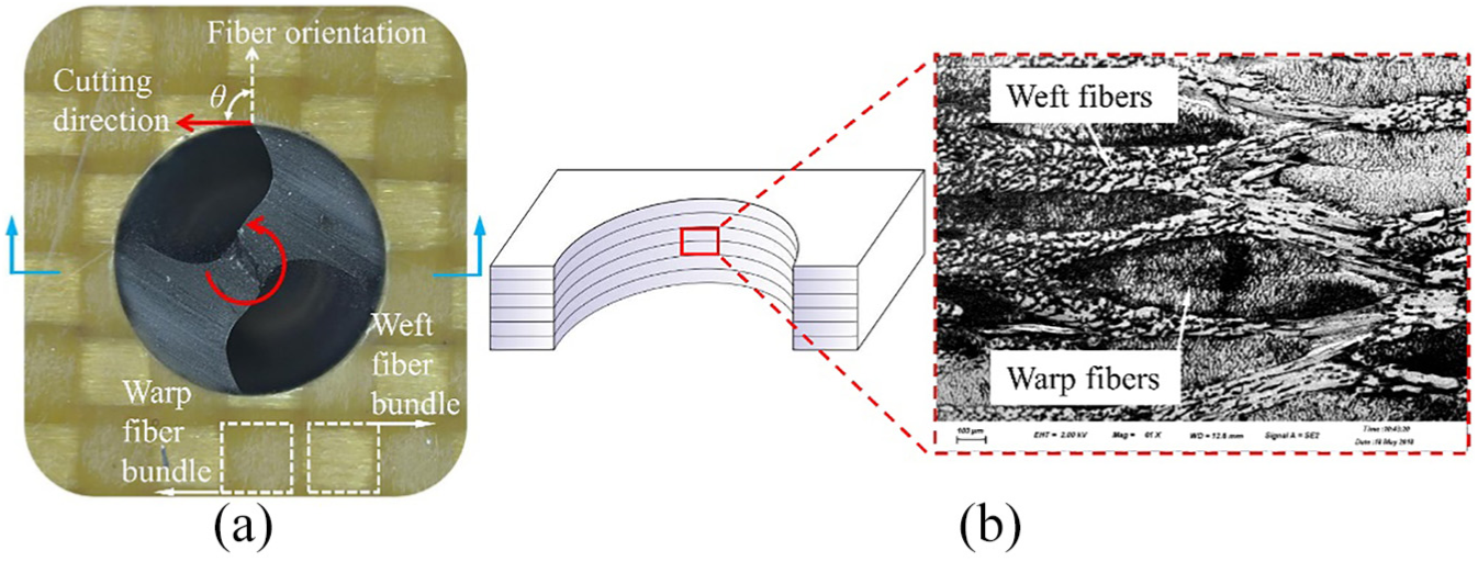
Selection of the region for morphology observation: (a) the exit plane of the workpiece and (b) structure of AFRP laminates.
The analysis of machining FRPs is closely related to the research scale of physical cutting between the tool and the fibres. On a macroscopic scale, the contact during drilling occurs between the composite laminate and the tool. However, on a microscopic scale, the region changes to the cutting contact between the fibres and the cutting edge. As a result, the mechanical properties of the elementary fibres need to be considered. Figure 20 describes the machining process when drilling a hole wall in an AFRP on the microscale. Because the interfacial bonding strength of an AFRP is much lower than that of a CFRP, the bonding strength of the matrix is not sufficient to maintain the aramid fibres under the cutting motion. Under the action of the cutting edge, bending deformations of the aramid fibres occur, as shown in Figure 20(a). Figure 20(b) illustrates the real situation of fibre shearing when drilling an AFRP. Due to the high mechanical properties of aramid fibres along the fibre axis, sliding between the fibre and the cutting edge occurs prior to shear failure. Therefore, the pure shearing action of aramid fibres cannot be performed, and the fracture surfaces of the fibres are inclined in the cutting direction. Moreover, the mechanical properties of the aramid fibres in the radial direction also substantially affect the surface morphology. Because the strengths of aramid fibres in the transverse direction are dominated by hydrogen bonding, 30 aramid fibres have lower compressive strengths than tensile strengths. Under the action of the relief face of the cutting edge, the fracture surfaces are split and then flattened into compressed extremities. Therefore, Figure 20(c) shows that the widths of fibre extremities are larger than the normal diameters of the fibres.
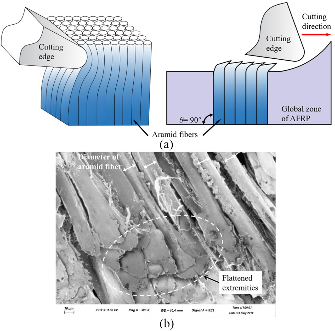
Drilling AFRP on microscale: (a) deformation and sliding of aramid fibres, (b) real situation of fibre shearing, and (c) flattened extremities of aramid fibres.
The influences of different cutting tools on the surface morphologies are presented in Figure 21. There is a similar phenomenon between the surface morphologies produced by twist drills and brad drills. The fracture surfaces of the aramid fibres are flattened under the action of the relief face of the cutting edge. Moreover, because of the machining temperature, the resin matrix is spread under the action of the cutting edge, and the matrix covers the fracture surfaces of the fibres. Therefore, the extremities of the aramid fibres overlap each other, and the fracture surface areas of the fibres are significantly increased. Furthermore, as shown in Figure 21(b), when drilling with a twist drill, many obvious burrs are located along the edges of the fibre extremities, which could be proof of the ductile fractures of the aramid fibres. In contrast, the edges of the fibre extremities cut by the brad drill are much smoother, as illustrated in Figure 21(a). Therefore, we can infer that the brad drill produces a more effective shearing action for the aramid fibres than the twist drill. Furthermore, it is worth mentioning that a different type of surface morphology is produced by the burr tool, as shown in Figure 21(c). The surface morphology produced by the burr tool is the smoothest among the three cutting tools. This phenomenon can be attributed to the special tool geometry of the burr tool. First, due to 11 helical edges along one helical line on the burr tool, the fracture surfaces of the aramid fibres are repeatedly trimmed by these cutting edges within one spindle revolution. Second, due to the multiple cutting edges on the burr tool, a substantial amount of cutting heat is accumulated, which softens the matrix more than the other two drills. As a result, a greater amount of matrix is spread by the cutting edges to fill the gaps among the fibres.
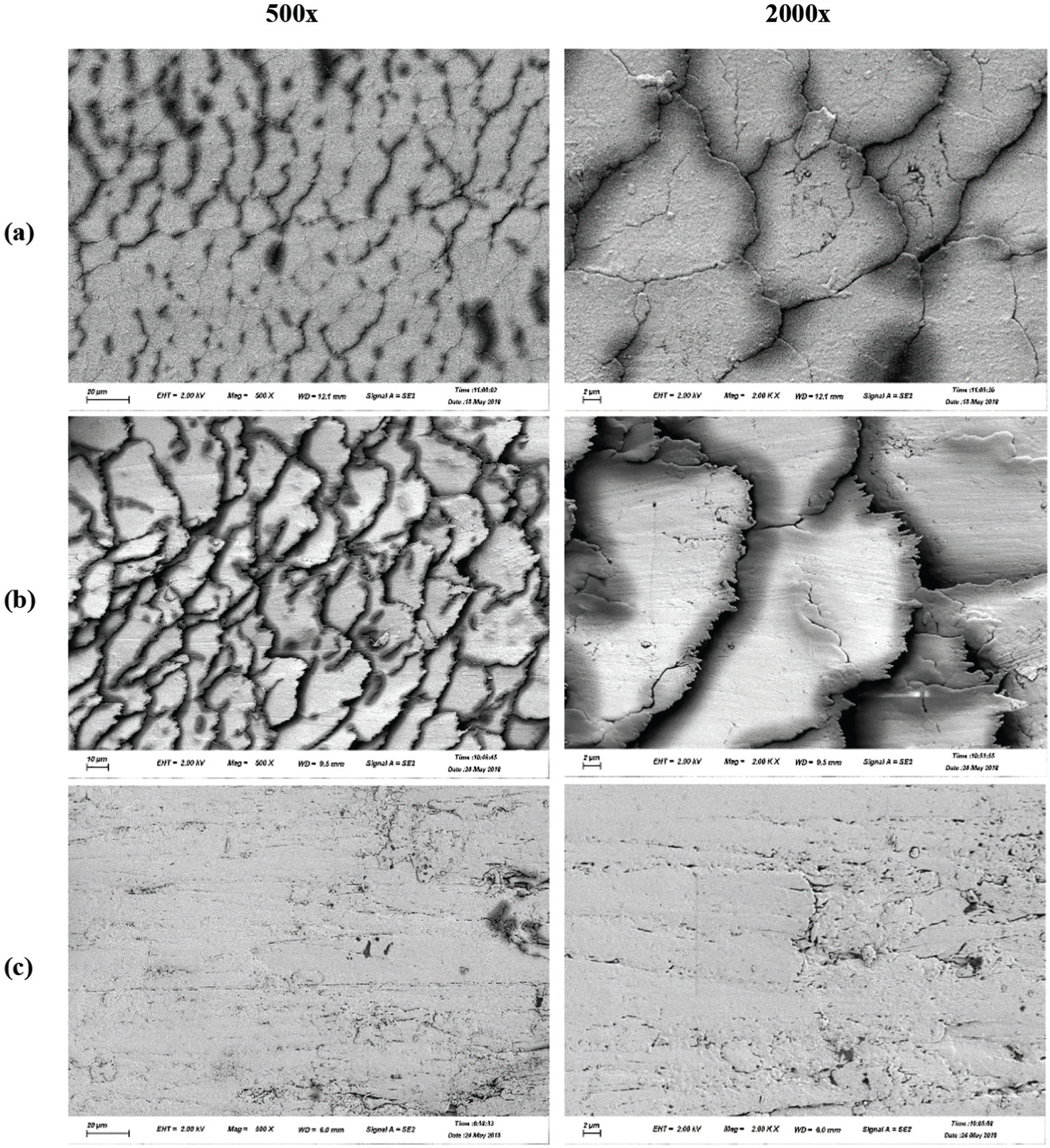
Surface morphology after drilling process (f = 40 mm/min, S = 4000 r/min, without collars): (a) brad drill, (b) twist drill, and (c) burr tool.
Conclusion
The article is devoted to investigating the cutting mechanism analysis and hole quality optimization for drilling AFRPs with three typical tools. On this basis, the influences of cutting parameters and collars on the thrust force and hole quality are revealed through systematic experiments. The conclusion of this article are listed below:
At the hole entrance, the uncut material is peeled and torn under the peeling action of the cutting edge of a twist drill, which causes severe fuzzing damage. Due to the positive radial rake angles of the burr tool and brad drill, the radial component of the cutting force can pull aramid fibres from the outside to the drill centre, which can effectively restrain the concession and deformation of aramid fibres, which reduces the fuzzing defect. In terms of the exit damages, the extrusion action of the chisel edge of the twist drill is the prominent trigger. Owing to the severe chip adherence, extensive exit defects occur when using burr tools. Due to the decrease in the thrust force and improvement in the shearing action, the brad drill produces the best hole quality among the three tools.
An auxiliary approach using collars is introduced to further improve the hole quality. When drilling with collars, the interfacial bonding strength between aramid fibres and the matrix is increased and correspondingly restrains the deformation of fibres and the deflection of uncut material. Therefore, under the action of collars, the abilities of the fibres to exhibit shear fractures are promoted.
Generally, a low feed rate and high spindle speed can reduce damage when drilling FRPs. However, when drilling AFRP, a high feed rate can promote the shearing action of the cutting edge and thus reduce the fuzzing defect. Due to the softened matrix, a high spindle speed may exacerbate interfacial debonding and fibre pull-out.
SEM analyses suggest that the pure shearing action of aramid fibres cannot be produced due to the properties of aramid fibres. The pressing action and spreading action of the cutting edge play important roles in the produced surface morphologies.
Footnotes
Declaration of conflicting interests
The author(s) declared no potential conflicts of interest with respect to the research, authorship, and/or publication of this article.
Funding
The author(s) disclosed receipt of the following financial support for the research, authorship, and/or publication of this article: This work is supported by the National Natural Science Foundation of China (Grant No. 51705362), the Science and Technology Development Fund of Tianjin Education Commission for Higher Education (Grant No. 2017KJ081), and Natural Science Foundation of Tianjin (Grant No. 18JCQNJC75600).