
Abstract
Remanufacturing is a promising technique for reducing manufacturing costs and material usage. This work presents a method for repairing casting parts using an additive metal-layer deposition process. To determine characteristics and mechanical properties of parts repaired using the proposed additive metal-layer-deposition-based method, tensile specimens were designed with grooves measuring 1 mm and 3 mm in depth. Two specific metal powders, AISI-P21 (SCM440) and AISI-H13 (SKD61), were melted using a highly focused laser, and molten droplets were subsequently built up layer-by-layer to fill-in the grooves. Mechanical and metallurgical characteristics of repaired parts were investigated via tensile and hardness tests and microstructural analyses. Experimental results demonstrate that the ultimate strength of specimens repaired using the proposed additive metal-layer deposition method measured approximately 9% lower compared with that of FC300. However, the mechanical strength of additive metal-layer deposition specimen was increased about 22% compared with that of welded specimen. Through this work, we can make a conclusion that the additive metal-layer deposition technique is well-suited for the repair and reproduction of castings.
Keywords
Introduction
Remanufacturing and repairing practices offer numerous benefits to companies, including significant reduction in manufacturing cost, modest energy consumption, and reduced material usage. Remanufacturing of large casting parts offers numerous economic advantages. Gray cast iron (FC300) is a commonly used casting material, and it offers such advantages as low melting point, low cost, high thermal conductivity, and a damping capacity 6 to 10 times greater compared with that of steel. It is, therefore, widely utilized in numerous industrial applications, including manufacture of machine tools, automobile components, and engine blocks.1–5 However, cast iron contains a large amount (more than 2 wt%) of carbon, thereby resulting in low ductility of the material. This makes it difficult to repair parts made of cast iron by means of a general welding process, because material properties of cast iron change easily, and high processing temperatures attained during welding lead to the generation of microscale cracks within its structure. FC300 castings are often repaired via gas-welding processes owing to the relatively low processing temperatures involved.6–10 However, when using gas-welding as well, great care must be taken to minimize the number of defects caused by prolonged heating of the material. In particular, the rapid heating and subsequent cooling that occurs during the welding process may induce phase transformations within the base metal and welded zone to form white cast iron. This makes the material within the repaired zone to become brittle, thereby generating significant amounts of carbon monoxide.11–15
To overcome abovementioned issues, the additive metal-layer deposition (AMD) technique was investigated for use in the repair of casting parts. AMD has recently been considered as a promising method to be employed in the repair of mechanical parts owing to its inherent characteristics of high efficiency and flexibility, comparatively smaller extent of heat-affected zone (HAZ), and retention of strong metallurgical bonds between the base metal and deposited material. 16 During the AMD process, a high-power laser beam is focused onto a damaged substrate, thereby causing it to melt microscale metal powder discharged onto the substrate via a dedicated nozzle. The powders are melted rapidly followed by spontaneous solidification on the target surface. Thus, the size of HAZ remains relatively narrow when compared against traditional welding processes. Over the past decades, a number of works concerning laser-based surface-repair techniques have been reported. Song et al. 17 investigated the repair of V-shaped grooves in medium-carbon-steel substrates using AMD. In their work, the mechanical properties of repaired layers were found to be greatly enhanced when compared against those of the original substrate. Wen et al. 18 utilized a laser hot-wire cladding technology in the repair of martensitic precipitation-hardened stainless steel. Borrego et al. 19 demonstrated the fatigue strength of laser-welded joints to be significantly lower compared with that of the base material.
Although laser-based repair techniques have been widely utilized for use in diverse industrial applications, there still exist some problems to be solved. In particular, finding a means to minimize microscale cracks generated at the bonding interface remains a hot research topic. When the heat generated during laser processing is absorbed by gray cast iron, carbon content in the grain structure becomes concentrated within the area exposed to the laser. This, in turn, leads to the generation of brittle ledeburite structures. Consequently, the repaired FC300 part becomes brittle and is mechanically unsound. 20 Some extant studies have reported the occurrence of metallic surface modifications during laser processing. Xu et al. 21 used an Nd:YAG laser for cladding along with high-strength steel (HSS) powder on a nodular cast-iron roll. Their results demonstrated the generation of several microscale cracks within the coating layer. Lestan et al.22,23 reported the use of a cladding method involving use of a Ni-based alloy and HSS powder along with heating of the substrate using a 1-kW ytterbium fiber laser. In their investigation, numerous cracks were observed at the interface between the coating and base metal. However, laser preheating of the cast-iron substrate was found to have reduced the number of cracks that appeared on the specimen. With the objective of eliminating the appearance of cracks at the repaired interface of cast iron coated with Ni-based alloy powder, Lin C, Chandra A, Morales-Rivas L, et al. 24 proposed the microstructural characteristics, metallurgy and mechanical properties of the repair weldments produced using fiber laser cladding. Yi et al. 25 proposed a dynamic self-preheating method to reduce thermal stresses within the substrate, and it was demonstrated that metallurgical microstructures within the repaired gray-cast-iron specimen are much better after treatment.
Nonetheless, most investigations concerning laser processing have focused on the use of either cladding or surface heat-treatment techniques. To the best of the authors’ knowledge, there exists no research that addresses repair of a damaged FC300 part using AMD technology and thereby achieving better mechanical integrity and quality. The proposed study suggests a new approach toward repair of FC300 casting parts, thereby evaluated the potential of the AMD technique in this regard. Observed mechanical properties and those of microstructures at the interface between the AMD-repaired layer and base metal have also been analyzed.
The experiment
The AMD system
The AMD process involves use of a high-intensity laser beam capable of instantaneously melting metal powder continuously supplied to the surface of a base metal, thereby enabling creation of thin metal layers. Figure 1 depicts a schematic diagram of AMD system and process.
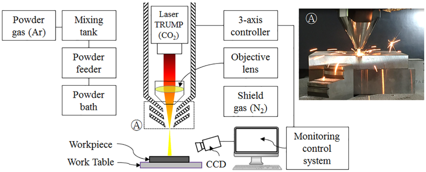
Schematic diagram of additive metal-layer deposition (AMD) process and focused beam, shielding gas (N2), and metal powder passing through nozzle. Inset Ⓐ is a photograph of nozzle in-processing.
A CO2 laser (TLF-4000, TRUMP Co., Germany) was employed as the heat source employed during the proposed AMD process. The laser was capable of providing a maximum rated power output of 2 kW with a beam diameter in the range of 0.8 to 1.0 mm. The said laser beam was emitted through a nozzle after being focused through an objective lens. The nozzle also discharged N2-shielding gas to prevent oxidation of the heated jointing zone. Metal powder with particle sizes ranging from a few tens to hundreds of micrometers were supplied through a coaxial powder nozzle along with argon gas, the flow of which controlled the amount of metal powder deposited. The nozzle was fixed to a three-axis stage, and its position in the x, y, z coordinate system could be controlled along programmed tool paths. The nozzle moved at an approximate speed of 850 mm/min, and the average thickness of the deposited layer measured approximately 0.25 mm. A charge-coupled device (CCD) camera was installed to observe and control the height of deposited layers in real time, and the laser output was controlled to ensure desired deposition of the metal layer.
Materials
To ensure material uniformity, a powder of the same material as the base metal must be used when performing the AMD-based repair process. However, there currently exist no available cast-iron powders. So, in this study, a near-spherical FC300 metal powder was fabricated at a laboratory level using a gas-atomizing method, as depicted in Figure 2, wherein FC300 specimen was placed in a crucible and melted by heating to temperature of 1400 °C.
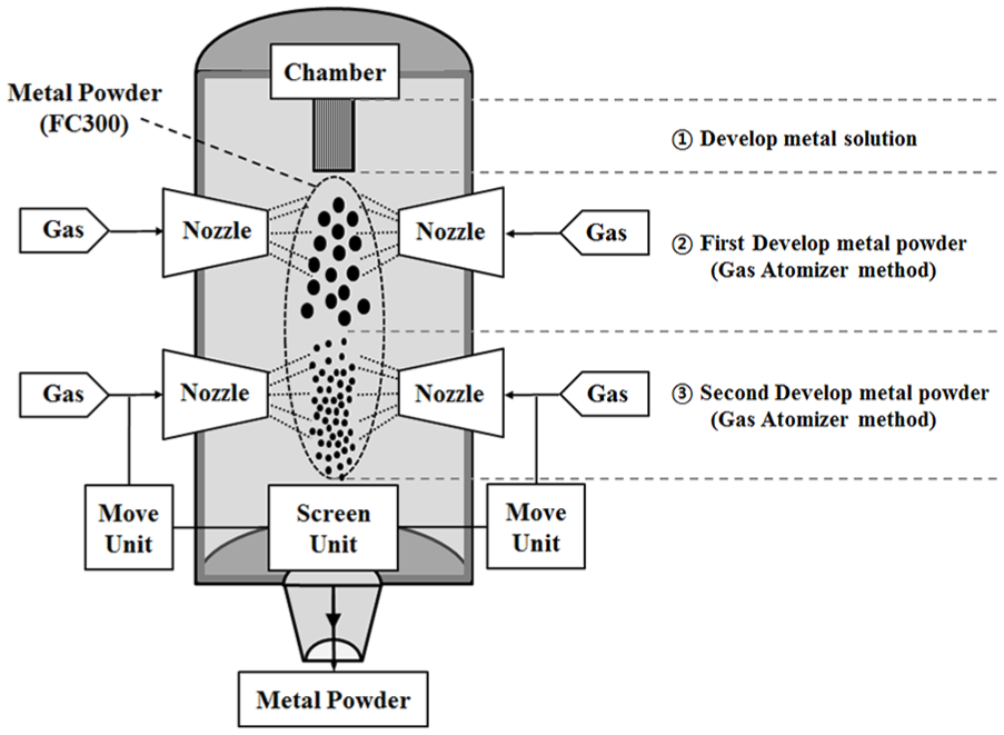
Gas atomizing process for fabrication of gray-cast-iron powders.
The molten metal was transferred into an injection chamber through a nozzle. At the same time, N2 gas, heated to the temperature of 500 °C, was injected at a pressure of 50 bar in order to produce fine powders having size in a range of 50 to 150 μm, as depicted in Figure 3(a). Cast iron, however, possesses carbon content of the order of 2.5% or more, and the structure of a material with such high carbon content contains voids due to generation of CO and/or CO2 gases during the AMD process. In this study, we also tried to use other metal powders AISI-P21 (SCM440) and AISI-H13 (SKD61) for repairing casting parts, and compared the repairing results obtained using three kinds of powder. Generally known, the AISI-P21 and AISI-H13 have high strength and good weldability characteristics. However, the contents of carbon and chromium in AISI-P21 were smaller those of AISI-H13, thus, we expected that AISI-P21 powder was better suited for AMD by minimizing microscale cracks at the interfaces or grain boundaries after the repair process.
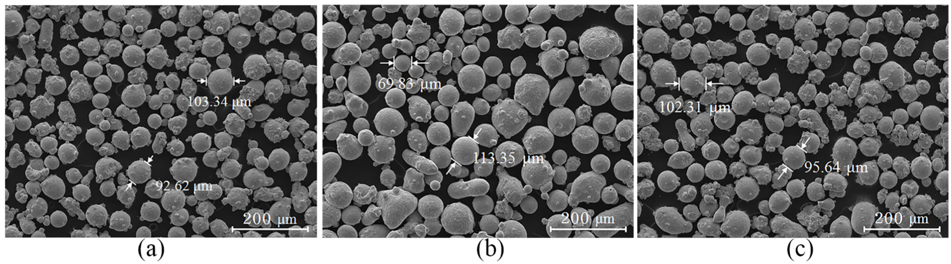
SEM (scanning electron microscopy) images of metal powders used in the AMD process: (a) FC300, (b) AISI-P21, and (c) AISI-H13. The sizes of particles are ranged in several tens to hundreds of micrometers.
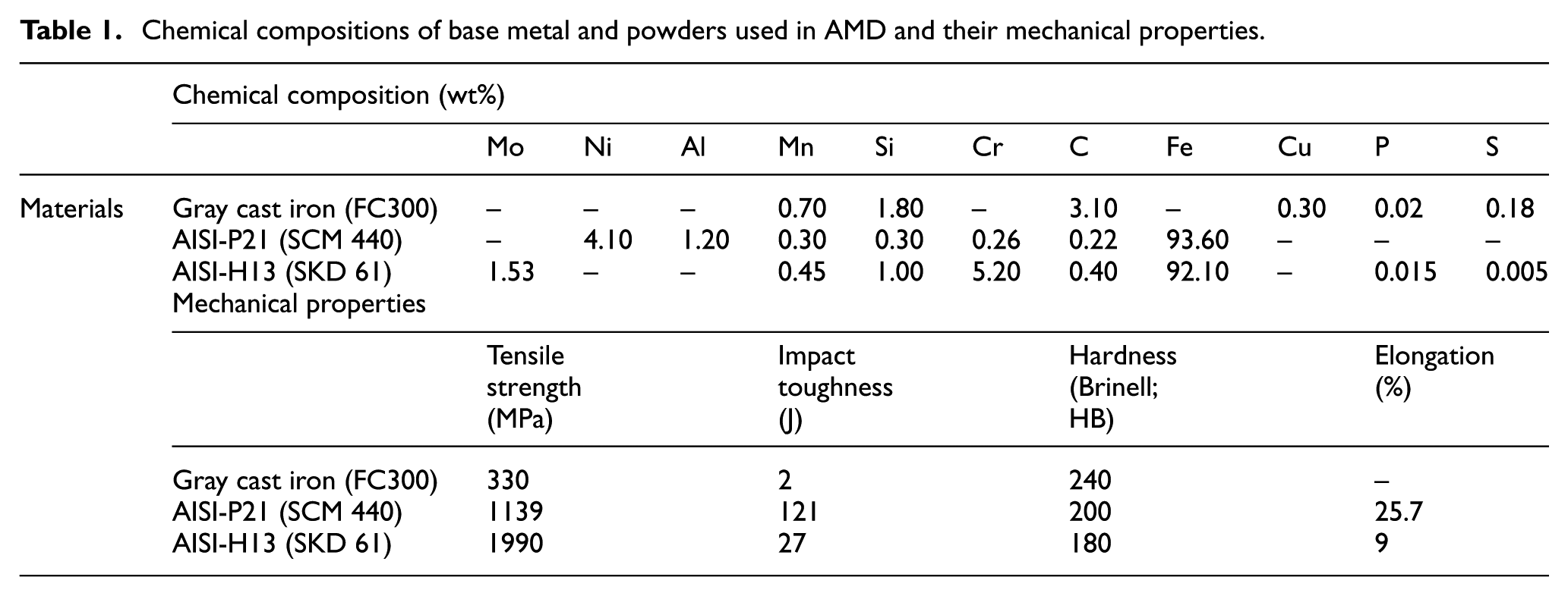
The powders used in the repair of the casted specimen contained particles with a nearly spherical shape and an average size measuring approximately 110 μm (a particle size ranging 10–160 μm). Figure 3(b) and (c) shows scanning electron microscope (SEM) images of FC300, AISI-P21, and AISI-H13 powder, respectively (supplied by Carpenter Co.). Table 1 lists chemical composition (wt%) of base metal and powder used in AMD process and some information of mechanical properties.
Chemical compositions of base metal and powders used in AMD and their mechanical properties.
Specimens repaired by AMD
Tensile specimens, as depicted in Figure 4, were fabricated to analyze mechanical properties after use of the AMD process, and to observe their metallurgical characteristics at the interface between the FC300 base material and deposited layer.
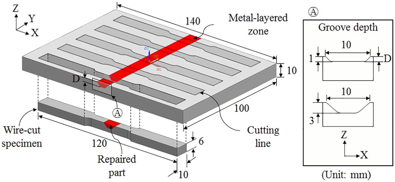
Schematic diagrams of tensile specimens repaired using molten AISI-P21 and AISI-H13 powders on a grooved FC300 base plate with each depth of 1 and 3 mm. The tensile specimens are wire-cut after repairing process, and the inset shows the cross-sectional shapes and dimensions of a groove.
The gravity casting process was used to fabricate an FC300 plate measuring 140 × 100 × 10 mm. Polygon-shaped grooves were subsequently machined into the plate up to depths of 1 and 3 mm with sides inclined at an angle of 45° each (right-hand insets in Figure 4). Melted powders were then deposited into the grooves, thereby attaining a height of 1 mm greater than the level of the base plate. The over-accumulated material was then removed via machining, thereby ensuring that the final specimen possessed the same surface roughness and exact height as the base material. Five tensile specimens, each measuring 10 mm in width, were prepared via wire-cutting in accordance with ASTM E-8M (Standard Test Methods for Tension Testing of Metallic Materials, 1997).
Results and discussion
Preliminary test for processing conditions
Basic experiments were first performed to establish the lamination condition of the FC300 metal powder fabricated as described in the previous section. These experiments were performed using several values of key parameters, such as laser power, powder feed rate, and nozzle moving speed. However, since the FC300 powder possesses high carbon content, oxidation occurs within the deposited zone and interface, albeit in the presence of the shielding N2 gas. Carbon monoxide formed during the AMD process, led to the generation of numerous pores along deposited tracks (see photos in the front of Figure 5(a)). Through the preliminary experiments, we found out the best conditions to minimize void amounts as laser power of 800 W, powder feed rate of 6 g/min, nozzle speed (NZ) of 850 mm/min, and gas flow rate (GFR) of 2.5 l/min. However, as shown in Figure 5(b), the material behaviors of repaired specimen were much weaker compared with those of the original material owing to the influence of defects. Based on these results, it was concluded that FC300 powder is not appropriate for use as a repairing material in AMD process.
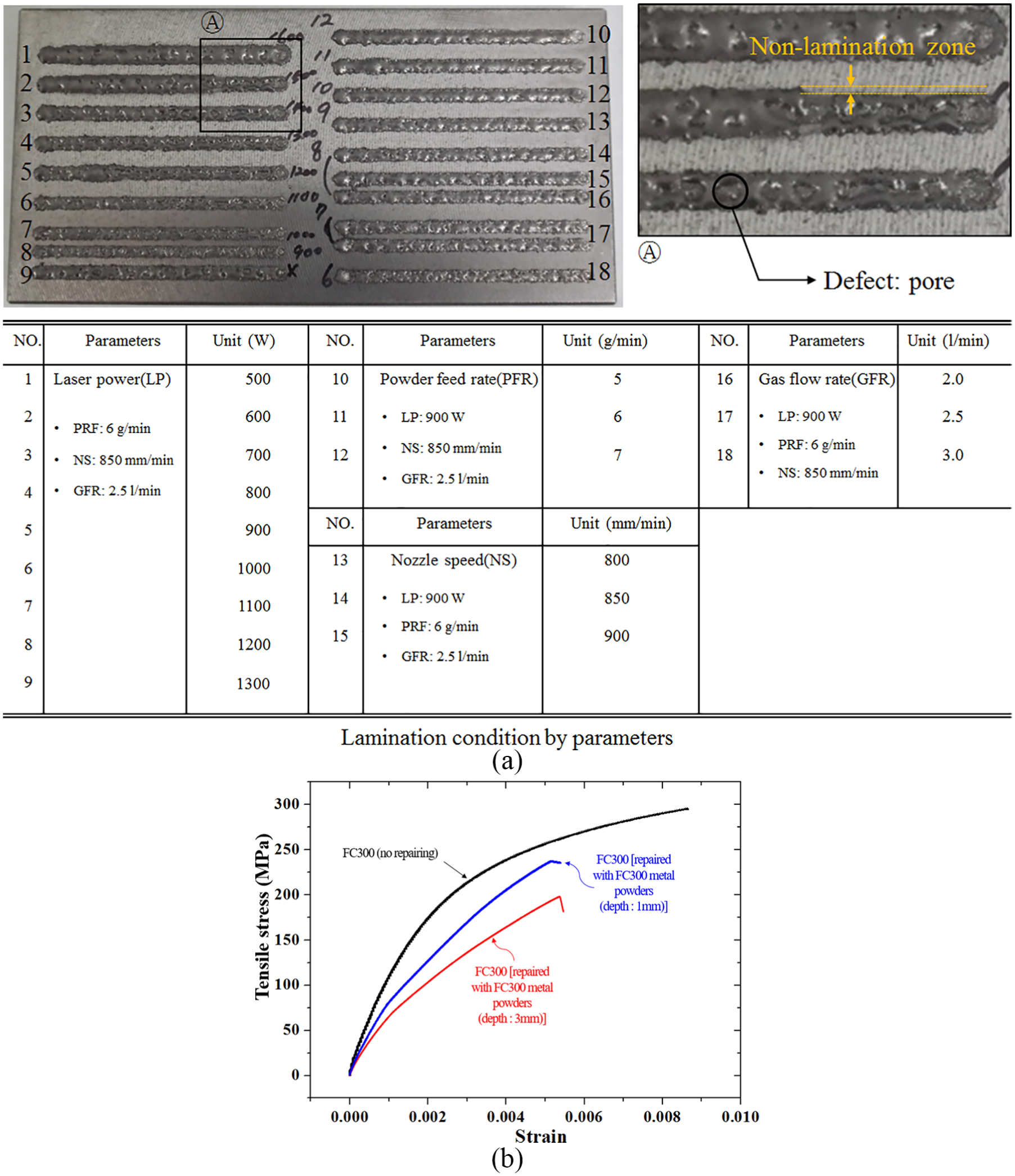
(a) Preliminary test results of metal deposition on a FC300 plate according to process parameters (laser power (LP) of 500–1300 W in the case of Number 1 to 9 with the fixing conditions of powder feed rate (PFR) of 6 g/min, nozzle speed (NS) of 850 mm/min, gas flow rate (GFR) of 2.5 l/min; powder feeding rate of 5 to 7 g/min from Number 10 to 12 with the fixing conditions of LP of 900 W, NS of 850 mm/min, and GFR of 2.5 l/min; nozzle moving speed of 800 to 900 mm/mm from Number 13 to 15 with the fixing conditions of LP of 900 W, PFR of 6 g/min, and GFR of 2.5 l/min; shield GFR of 2 to 3 l/min from number 16 to 18 with the fixing conditions of LP of 900 W, PFR of 5 g/min, and NS of 850 mm/min) and (b) tensile test results of each specimen.
Meanwhile, preliminary experiments were conducted using the AISI-P21 and AISI-H13 powders to establish optimum processing conditions. Metal lines were deposited along single tracks on a flat FC300 using AISI-P21 and AISI-H13 powders, depicted as cross-sectional images in Figure 6. The porosity of deposited metal lines was observed via optical microscopy. Through a process of repeated experiments, operating conditions free from generation of defects, pores, cracks, and balling on deposited lines were determined. During experiments, an increased probability of pore generation was observed in the event of occurrence of the balling phenomenon. From the parametric study, the best operating conditions were, thus, defined as laser power of 900 W, powder feed rate of 5 g/min, NZ of 850 mm/min, and GFR of 2.5 l/min, as shown in Figure 6(a) and (b).
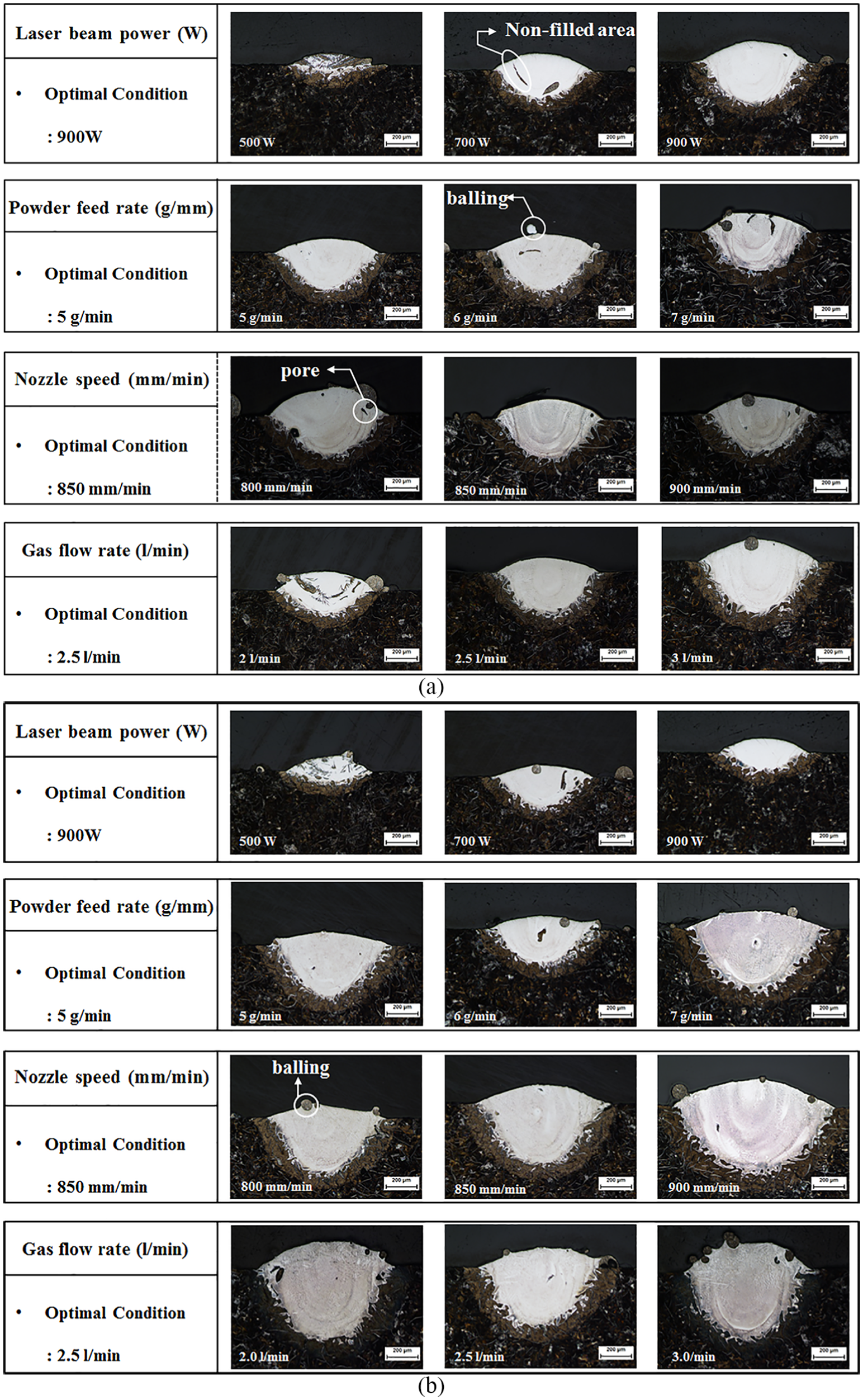
Experimental results of single-track deposition on a FC300 plate; line deposition with (a) AISI-P21 powders, and (b) AISI-H13 powders.
Metallurgical microstructure of AMD processed parts
Powders of two different materials were deposited in the grooves, shapes of which were assumed to represent damaged zones within a casting part. The repaired parts of each specimen were wire-cut along the thickness and polished to enable observation of the interface microstructure for analysis of metallurgical characteristics. Nital (4%) solution was used for etching specimens to clearly observe microstructures around interface zones. The overall grain size and surface structure were examined via optical microscopy (OM; MA200, Nikon, Japan) and SEM (MIRA-I-LMH, Tescan Co., USA).
AISI-P21 and AISI-H13 powders were used to laminate the FC300 casting, and defect analysis of each repaired area was performed via computed tomography (CT). The AMD results using AISI-P21 and AISI-H13 powders are shown in Figure 7(a) and (b), respectively.
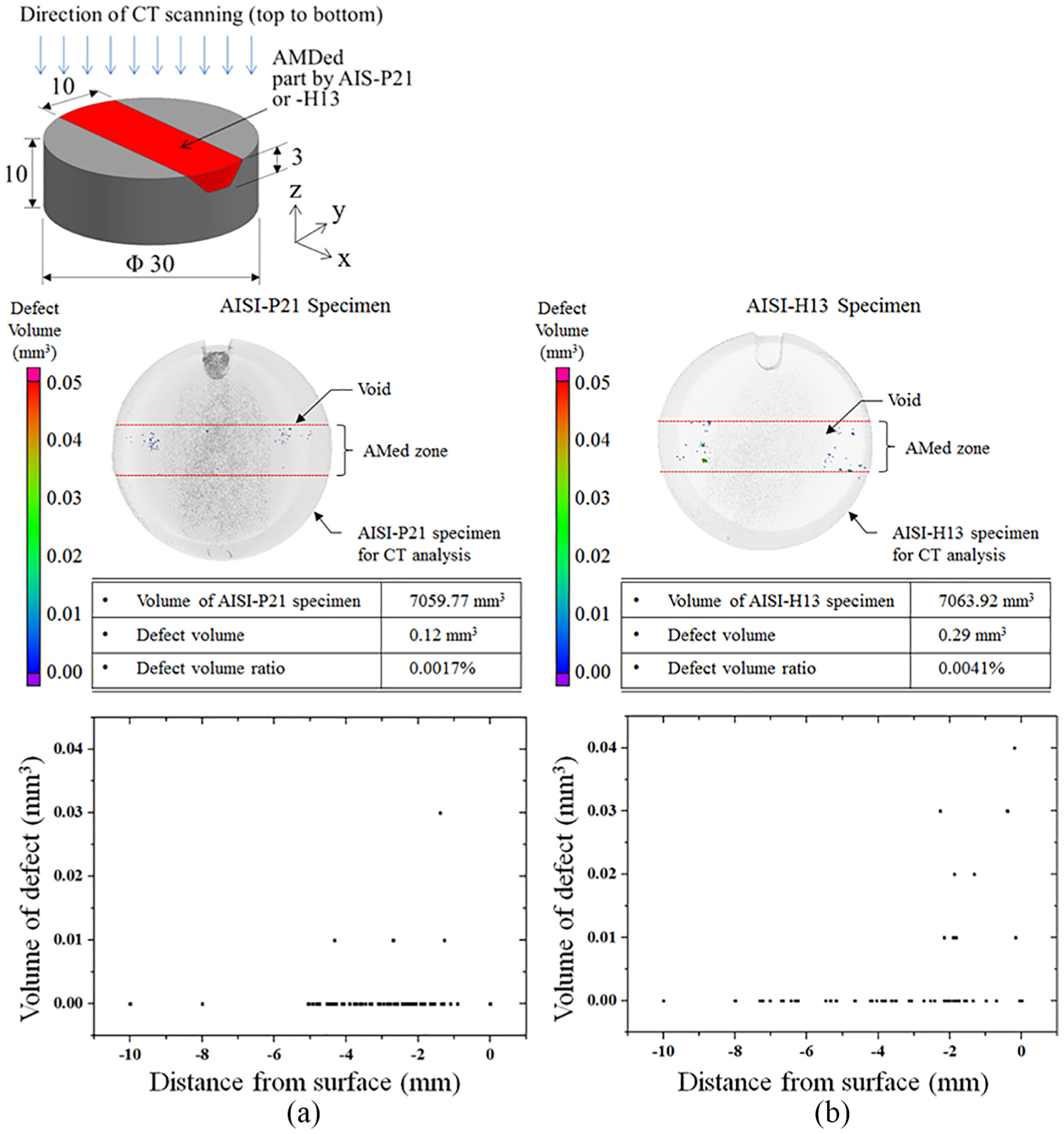
Images of computed tomography (CT) after deposition of molten (a) AISI-P21 and (b) AISI-H13 powders on a grooved FC300 plate. Small dots represent void defects in both images distributed near the interfaces, but the volumetric size of voids is not big one.
From the defect analysis, the sizes of maximum voids after the deposition of AISI-P21 and AISI-H13 were observed as 0.032 and 130.043 mm3, respectively. However, most voids were observed to have a volume of roughly 0.002 mm3 or less per void. The total volumetric percentage of voids was approximately 0.0017 and 0.0042 vol% with each deposition of AISI-P21 and AISI-H13, respectively. We believe that the presence of such small volume voids does not greatly influence on its mechanical properties. It is assumed that the voids were generated by chemical reactions between carbon and oxygen at the interface during the AMD process. The high-temperature ambience around the interface causes carbon present within the FC300 structure to be oxidized, thereby resulting in generation of gaseous CO, which subsequently gets trapped. Furthermore, any moisture that may be present within the melting zone dissociates into oxygen and hydrogen and subsequently recombines with carbon to form CO gas. In addition, there also exists a slight possibility of the shielding N2 and/or inert Ar gases (used to carry the powder) to be trapped within the molten metal. In general, to prevent the formation of voids caused by generation of CO, the molten metal must be completely isolated from the surrounding air through use of either vacuum or a shielding gas. In addition, the presence of any moisture can be eliminated by preheating or drying the base metal and powder prior to commencement of the deposition process. In future endeavors, the authors plan on taking up studies focusing on the investigation of probable reasons behind void generation at the interface.
An increased number of cracks were observed near the interface region of the sample prepared using the AISI-H13 powder compared with that prepared using AISI-P21. The results of electron probe microanalysis (EPMA) and chemical components are summarized in Figure 8(a) and (b) and Table 1, which shows that the AISI-H13 powder contains a higher concentration of curable elements such as C, Mo, and Cr compared with those of AISI-P21. This makes the AISI-H13 material more brittle, and hence, possesses lower ductility. It was, therefore, considered that cracks were generated in the vicinity of the interface owing to differences in the amount of thermal expansion of biomaterial interfaces under high-temperature conditions of AMD processing.
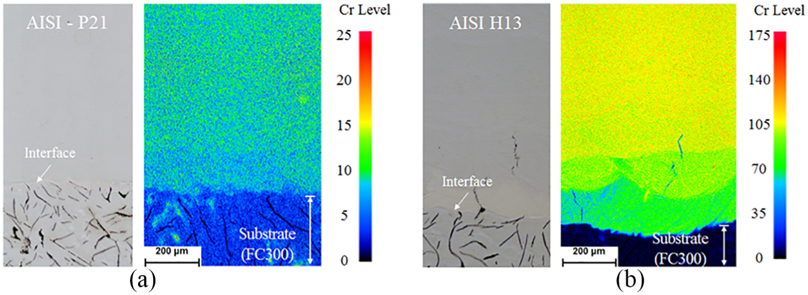
EPMA (electron probe microanalysis) mapping results demonstrate chromium distribution near the repaired zone with (a) AISI-P21 and (b) AISI-H13 powders, respectively. The density of chromium in AISI-H13 is much higher than that of AISI-P21.
The metallurgical microstructures of the repaired zone and interface were observed using SEM and optical microscope. As shown in Figure 9(a) and (b), graphite and pearlite grain structures, which are typically observed in the casting part, were formed in both cases.
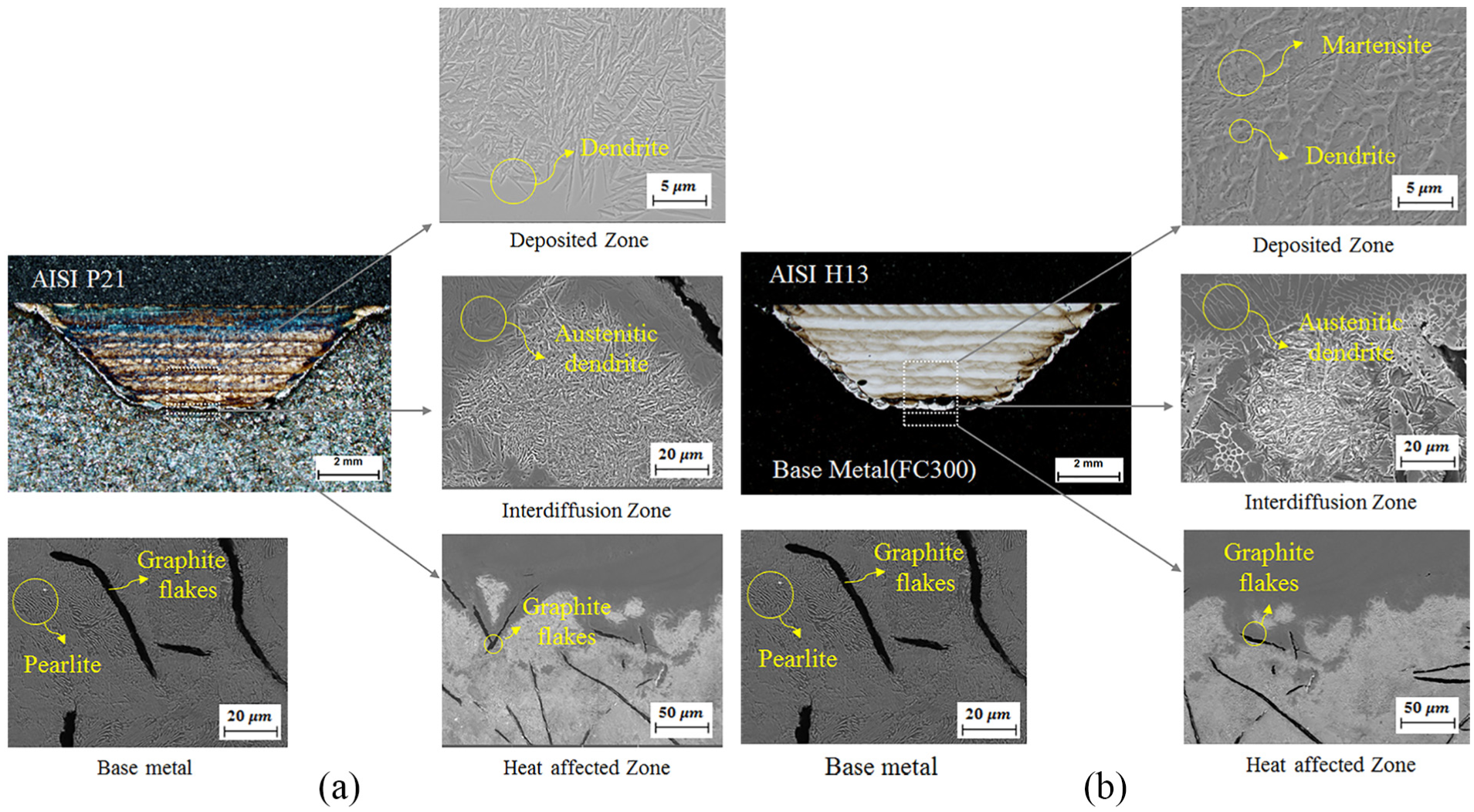
Microstructural images of specimens deposited with (a) AISI-P21 and (b) AISI-H13 powders. In case of AISI-H13 powders were used, martensite structures were obviously observed at near interfaces due to higher carbon contents.
In the HAZ located below the repaired interface, it was observed that pearlite structure of the base metal was transformed into martensite during the deposition process, because the temperature within HAZ was raised above that corresponding to the A3 transformation point of cast iron during AMD. This was immediately followed by rapid cooling. Compared to the base metal, the increased hardness of the repaired specimen could be attributed to existence of the abovementioned high-temperature HAZ. However, it was observed that the depth of HAZ below the interface measured only 102 μm, which is not significantly large (refer Figure 10(a) and (b); hardness measurement results around the interface). Also at the repair interface, austenitic dendrite structures were observed, as depicted in magnified images of Figure 9(a). During initial deposition, the base material area was melted, thereby diluting the carbon content in the base metal and increasing carbon concentration in the initial deposition region. It was, therefore, determined that the austenite structure was stabilized under high-temperature conditions during AMD. Another important point is that the initial deposited material was melted again to form a “remelting zone” during deposition of the second layer over the initial layer. Further dilution of the initial and second deposition layers may also have occurred. However, the relatively low carbon content within the “remelting zone,” compared with the initial deposited layer, results in the formation of plate martensite. Therefore, both the initial and second deposited layers demonstrated high hardness values.
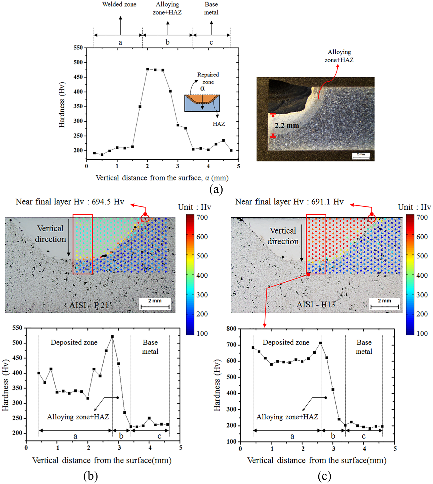
Hardness distributions on the repaired zone using (a) welding process, (b) AMD process with AISI-P21 powders, and (c) AISI-H13 powders. Maximal hardness in the interfacial region repaired by welding, AMD with AISI-P21 and AISI-H13 powder was about 477, 540, and 710 Hv, respectively (a, b, and c in the figures denote the zones of deposition, interface, and base metal).
Evaluation of hardness on the repaired zone
Hardness of the repaired part was measured to quantitatively understand changes in material properties brought about by the AMD process. The parts were cut into sections to measure hardness using a commercially available Mitutoyo HM-200 micro-vickers hardness tester. A load measuring 4.9 N was applied for 10 s during the hardness test. Hardness values were determined as the average of values obtained over five trials performed using the same specimen with the load being applied at different points. As shown in Figure 10(a) to (c), the hardness was measured repeatedly as a matrix-array form around the repaired zone in three different cases. Hardness values were expressed as a mapped image to understand easily the variation and distribution.
In Figure 10, the maximum hardness in the specimen repaired by welding was 477.7 Hv, however, the maximum hardness of repaired zone by the AMD process was much higher than the value for welding about 13% to 48%. The maximum hardness, when repaired by welding and AMD processes, occurs in HAZ. The reason is that in the HAZ, a quick quenching results in the formation of martensite structures and that makes a higher hard region. However, the difference between repairing with welding and AMD processes is the size of the HAZ. When repaired by the welding and AMD processes, the sizes of HAZs are about 2.2 mm and 102 μm, respectively. This big difference in the size of HAZ affects the mechanical properties of the repaired part.
The deposited zone with the AISI-P21 powders exhibited an average hardness of 337.9 Hv, which was somewhat uniformly distributed over the deposited area. The hardness value was found to sharply increase in the vicinity of HAZ near the interdiffusion region, whereas a maximal hardness of 540.2 Hv was measured, and the average hardness of 212.4 Hv was recorded in the base metal (FC300). The hardness distribution for the specimen deposited with the AISI-H13 powders indicated a more-or-less similar trend as that demonstrated by the AISI-P21-deposited specimen. However, the average hardness in the deposited area of the specimen deposited with AISI-H13 powder measured as 585.7 Hv, approximately 73.3% greater compared with that of the AISI-P21-deposited specimen. And, the maximal hardness near interface zone reached 730.2 Hv. The reasons behind this increase in the observed hardness distribution include the fact that the carbon content in the AISI-H13 powder is 45% greater compared with that in the AISI-P21 powder (which significantly affects the overall hardness of the material) as well as presence of a large amount of high-strength elements, such as Mo and Cr within the AISI-H13 structure. From the test results, the hardness of repaired parts was observed to have increased over that of the original base metal owing to presence of high-strength elements within the AISI-P21 as well as AISI-H13 powder. In addition, one could observe the presence of a narrow HAZ near the interface. However, both AMD specimens demonstrated corresponding maximum hardness values (694.5 Hv for AISI-P21 and 691.1 Hv for AISI-H13) at or near the interdiffusion point of the deposited top surface (refer Figure 10(b) and (c)). This was considered to be caused by process completion at the boundary, at which rapid cooling led to quenching of the local zone.
Comparison of tensile strength
Tensile tests were conducted on each repaired specimen by welding and process for analysis of mechanical properties. Based on the test results, it was known that the areal size of HAZ affects tensile elongation. Therefore, we can make a conclusion that minimizing HAZ is an important factor in repairing casting parts in terms of mechanical integrity. It explains why the AMD is meaningful in repairing process.
Tensile strengths of specimens repaired using different powder materials (AISI-P21 and AISI-H13) and different groove depths (1 and 3 mm) were also compared. A hydraulic tensile tester (MTS-810, MTS Systems Co., the United States) was used at room temperature, and the tensile test was performed at a loading speed of 0.1 mm/min. Figure 11 shows optical microscopy and SEM images of the fractured surfaces after tensile tests.
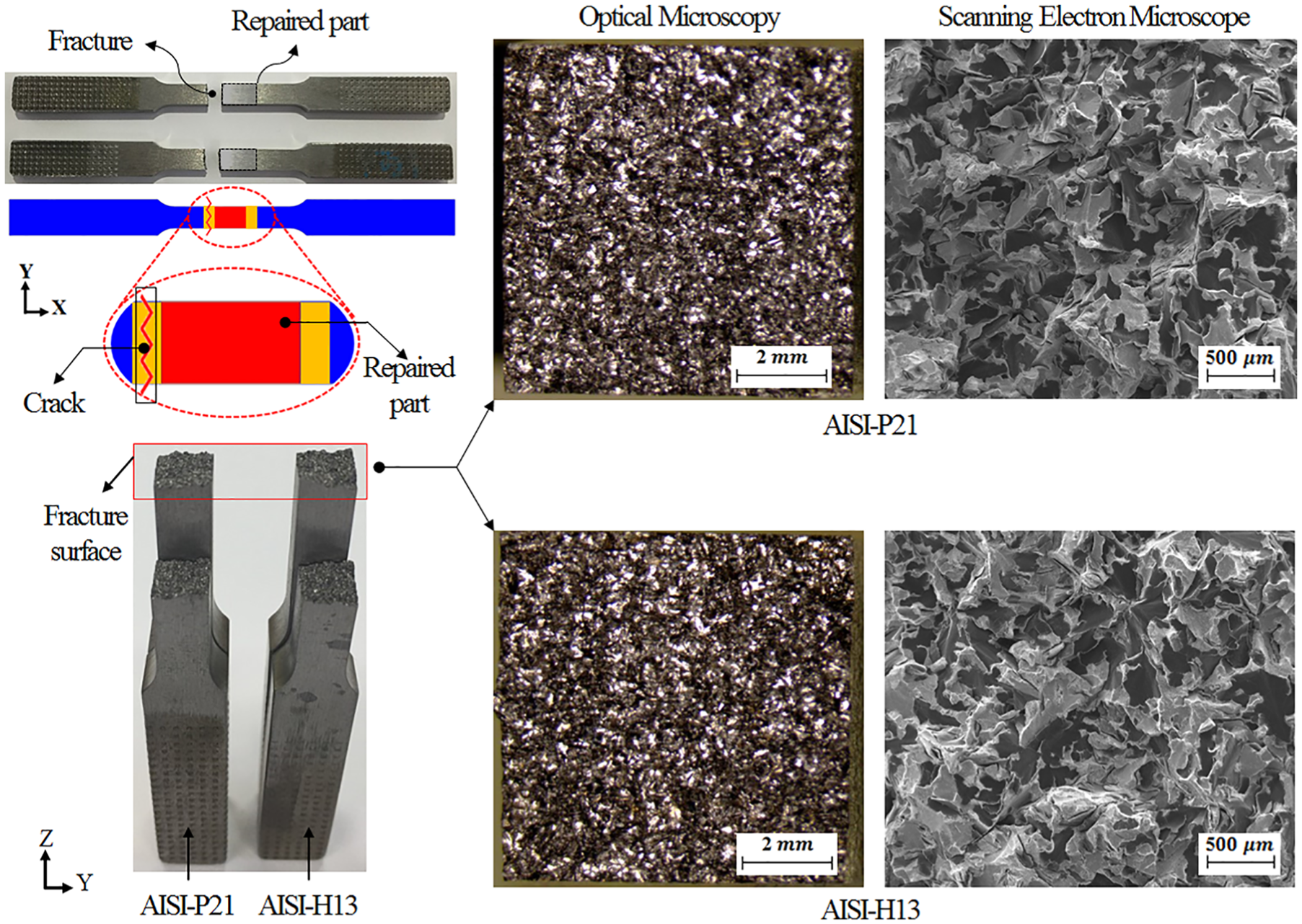
Fractured specimens partially AMDed (additive metal-layer deposition) with AISI-P21 and AISI-H13 powders. In both cases, brittle fractures (such as intergranular fracture) were observed at the end of a groove.
Fractures in all cases were observed to occur not in the repaired zone, interfacial zone, or HAZ, but within the original base FC300 metal. This implies that parts repaired through use of the AMD process demonstrated much high mechanical stability, despite the presence of small-sized voids at the interface. However, the fractures seemed to be initiated at the end of HAZ on the top surface that had the highest hardness in the repaired zone. Figure 12(a) and (b) compares the tensile testing results among three cases; repaired by weld and AMD with the groove depth of 1 and 3 mm.
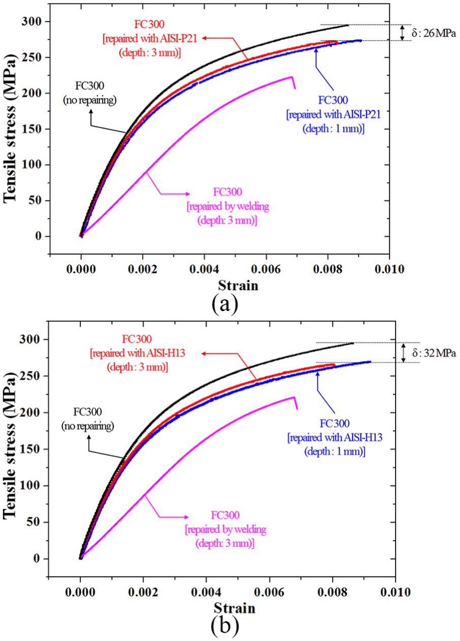
Comparison of tensile test results of specimens having grooves with 1 and 3 mm in depth repaired by welding and AMD with (a) AISI-P21 and (b) AISI-H13 powders. Compared to the original raw FC300 material, the maximal fracture stress was reduced to about 14.3% in the AMDed (additive metal-layer deposition) ones. However, the tensile strength was somewhat increased about 22% when the AMD was utilized comparing with the welding.
Here, tensile strengths of AISI-P21 and AISI-H31 specimens were observed to be less compared with those of the FC300 base metal (tensile strength of FC300 measures approximately 300 MPa) by approximately 8.3% and 9.3%, respectively. Repaired specimens with 1 mm grove depth exhibited an increase in elongation of 6.9% and 7.0% in the AISI-P21 and AISI-H13-deposited specimens, respectively. However, specimens with 3 mm groove depth exhibited a reduction in elongation of 10.8% and 13.6%, respectively, in the AISI-P21 and AISI-H13-deposited specimens. The mechanical strength of gray-cast-iron specimens repaired using the AMD process was found to have reduced by approximately 10% when compared against that of the original gray cast iron. In addition, the elongation of repaired specimens was changed depending on groove depth. Observed results demonstrate the possibility of use of the AMD process for repairing and remanufacturing casting parts.
Conclusion
The proposed AMD process demonstrates great utility in applications concerning the repair of metal castings, while reducing material usage, energy consumption, and cost, thereby facilitating realization of green remanufacturing. In the proposed study, two different powdered metals AISI-P21 and AISI-H13 with particle diameters ranging from 50 to 150 μm were used in an AMD-based repair process. The repaired specimens demonstrated the presence of voids and changes in the metallurgical microstructure of the base metal in the vicinity of deposition interfaces. However, the tensile strength of specimens repaired using the proposed AMD process was observed to have reduced by less than 10% when compared against the tensile strength of the base metal. HAZ depths of the two specimens were also found to be negligibly small measuring approximately 0.102 mm. The specimen repaired using the AISI-P21 powder demonstrated fewer cracks and lower hardness values. Thus, it may be concluded that compared with the AISI-H13 powder, AISI-P21 performs better in terms of AMD-based repairing of FC300 parts. However, the tensile strength of a specimen was dramatically increased about 22% comparing AMD-based repairing process and conventional welding process due to the narrow HAZ. Through this work, we believe that the proposed AMD with AISI-P21 and H13 powders has some advantages comparing with conventional welding–based repairing process, so it can be utilized to repair casting parts in industrial applications.
Footnotes
Declaration of conflicting interests
The author(s) declared no potential conflicts of interest with respect to the research, authorship, and/or publication of this article.
Funding
The author(s) disclosed receipt of the following financial support for the research, authorship, and/or publication of this article: This research was supported by the Basic Science Research Program through the National Research Foundation (NRF) of Korea, funded by the Ministry of Education (Grant 2017R1D1A1A09000923) and supported by the “Human Resources Program in Energy Technology” of the Korea Institute of Energy Technology Evaluation and Planning (KETEP) granting financial assistance from the Ministry of Trade, Industry & Energy, Republic of Korea (Grant 20184010201660).