
Abstract
The manufacturing of sound forgings from large steel ingots requires that internal cavity defects generated during the steel ingot solidification process be compressed by open die forging. The forging ratio that is generally recommended to remove internal defects in large forged products is 3S (threefold); however, the practice lacks a theoretical basis. In this study, a forging experiment and a finite element analysis were performed to investigate the correlation between the forging ratio for large steel ingots (3S) and the cavity closure behavior. First, a hot compression experiment was performed by varying the temperature and strain rate, and the flow stress data observed in the experiment was applied to the finite element analysis. In the experiment for the cogging process, the forging ratio was applied to an actual non-compressive defect material. The finite element analysis was performed using the same forging path as the forging experiment. In the cogging experiment, cavity closure was found by ultrasonic inspection at the forging ratio of 2.9S. The finite element analysis showed that the size of the cavity was significantly decreased at the forging ratio of 2.9S. A finite element analysis was also performed to investigate effective strain and hydrostatic stress at the forging ratio of 2.9S. Finally, this article provides the theoretical basis for the limitation of the internal defect size in initial materials, the threshold effective strain, and the limiting forging ratio of forged products to ensure the internal soundness of large forged products.
Keywords
Introduction
To meet the needs of modern power generation facilities and aviation and wind-power generation industries, super-large steel ingots of 100–500 tons are now being manufactured. As the size of steel ingots has increased, there is an increasing possibility that defects generated in the steelmaking process may remain in the ingots, including segregations, cavities, and deoxidation products, which can occur during the steel solidification process. Hot open-die forging is a process where the cavities, micro-porosities, and segregations generated in the steel ingot casting process are removed to increase the internal quality of steel products and to give them a form similar to that of the final products. The forging process of large steel forgings has often relied on experience obtained at actual industrial sites. However, as the demand for large forgings has increased, various studies have been conducted on the forging ratio, forging temperature, and tool design to prevent internal defects in the forged products.
Early studies on the formability of free-dig forging focused on the formability and deformation of modeling materials, such as wax, lead, and plasticine. In an attempt to ensure the internal soundness of forged products, Erman et al. 1 performed various tests using plasticine to investigate the effects of various factors, such as ingot shape, mold shape, temperature gradient, and process design. Further research was carried out on aspect ratio, press speed, and lubricants to analyze strain rate distribution in the upsetting process. 2 Subsequently, advances in finite element analysis methods made it possible to predict metal flow, shape defects, and temperature distribution in upsetting, radial forging, and cogging processes by varying the shape and dimensions of molds. Cho et al. 3 performed a three-dimensional (3D) thermo-viscoplastic finite element method to analyze the cogging process and assessed the effects of forging process parameters associated with the shape and aspect ratio of molds, temperature distribution effects, and pressing operations. Tamura and Tajima, 4 through a 3D finite element analysis of rigid plasticity, proposed a new pass schedule aimed at improving the homogeneity of cast structures and optimized anvil-shape parameters that affect the dimensional precision and forging defects in the manufacturing of circular billets via open die forging process. 5 Park and Kobayashi 6 conducted the rigid plasticity finite element analysis to study shape change according to friction conditions in a simple block model; they verified that their analysis results coincided with corresponding experimental results. Cho et al. 7 applied the 3D thermo-viscoplastic finite element method to compare the internal strain rate, hydrostatic stress, and temperature distribution in the cogging process for two cases of using a V-shaped die and using a flat die. As a result, they found that the internal strain rate at the center of the cast ingot after the cogging process was higher when the flat die was used than when the V-shaped die was used. Under two-dimensional (2D) plain-strain conditions and 3D conditions for both V-shaped and flat dies, Christiansen et al. 8 carried out a finite element analysis and cogging tests of ingots containing cavity defects in their inner diameters. As a result, it was verified that the V-die was more advantageous than the flat die in terms of cavity closure. Li and Pan 9 proposed a multi-stage bending process to control failures in bending operation of large-scale forging and performed finite element analysis to optimize die shape and forging process. The trial production was carried out by the proposed method and the efficiency of the multi-stage construction method was validated. Liao et al. 10 verified feasibility of parameter study and finite element analysis technique to investigate the process factors of forging operation for the forging shape stability in mass production. Recent studies have performed shape prediction of forged products and investigated methods to increase the homogeneity of the internal microstructure; further analysis has been done of forming limits in an attempt to remove defects from raw materials. Park and Yang 11 performed finite element method modeling and experimental tests to assess the efficiency of cavity closure and proposed a mechanism that describes cavity closure and leads to bonding phenomenon under high-temperature and high-pressure conditions. Also, Park and Yang 12 applied the thermo-viscoplastic finite element method and Taguchi method to analyze the cavity closure, which was found to be affected by the aspect ratio and shape of the applied mold. Maidorn and Blind 13 suggested the possibility of defects and damage in steel forgings caused by cavity defects occurring during the casting process, such as segregation and shrinkage cavities. Fukui et al. 14 investigated cavity closure under plane strain conditions in circular, hexagonal, and rectangular steel ingots with different types of dies and found that compressive hydrostatic stress has a significant effect on cavity closure. They verified through a finite element analysis of rigid plasticity that the upsetting process alone may not affect cavity closure forging, but may ensure the diameter and forging ratio needed. Dudra and Im 15 analyzed the effect of cavity closure in plane strain in terms of hydrostatic stress and effective strain, showing that effective strain is a better predictor of cavity closure than hydrostatic stress and that a V-shaped mold is more effective for cavity closure in a core part than a planar mold. Zutang and Meng 16 investigated the mechanism of cavity closure depending on the cavity shape and the material shape in terms of stress and strain to optimize the order of working procedures in the cogging process. Kwon et al. 17 analyzed the cavity shape and behavior before and after forging using an X-ray diffractometer with a miniaturized ingot made of AISI 4140 (SCM440) material, to analyze cavity closure behavior and to measure the threshold effective strain of cavity closure. Lee et al. 18 quantitatively analyzed the effective strain of closed cavities and non-closed cavities through finite element analysis and suggested that the threshold effective strain for cavity closure was over 0.6 by comparing the analytical results with experimental results. Chen et al. 19 verified the theoretical analysis results of a porous model via finite element analysis and further established standards for the prediction of multi-channel cavity closure using a simplified model. Saby et al. 20 discussed the limits of both the macroscopic and micro-analytical approaches with regard to cavity closure and further proposed an alternative mesoscale approach based on finite element analysis. These studies have verified that cavity defects can be removed by applying an appropriate forging ratio, but no study has been conducted to investigate the limiting forging ratio for manufacturing defect-free forged products at actual industrial sites.
This study was conducted to assess the validity of the forging ratio which is the ratio of elongated length and original one in cogging operation. Minimum 3S ratio is commonly required in the forging process design at actual industrial sites. 21 Materials having internal defects were formed by cogging at various forging ratios, and the closure of internal defects was examined using ultrasonic inspection. In addition, a finite element analysis was performed to analyze variations in the effective strain and hydrostatic pressure stress at the cavity closure part, which cannot be measured experimentally. The validity of the commonly applied 3S forging ratio was assessed on the basis of results from the finite element analysis and the forging experiment.
Experimental
Flow strength of cast ingot material
The material used in this study was 42CrMo4 (AISI 4140 equivalent), which is a medium carbon alloy steel material containing 0.4% carbon. Table 1 shows the chemical composition of the material. The hot flow stress of the material used in actual free-die forging should be applied to obtain quantitative results about the hot deformation behavior and the cavity closure of the remaining internal cavities in the finite element analysis. Therefore, a hot compression experiment was performed by taking specimens from the cast round bloom. The specimens were taken from an equi-axial area which accounted for over 50% of actual large ingots. The hot compression experiment was performed to measure hot flow stress depending on temperature, strain rate, and height reduction ratio. For experimental conditions, the temperature was 1000 °C–1250 °C, the strain rate was 0.01–10/s, and the height reduction ratio was 50% or higher.
The chemical composition of 42CrMo4 (AISI 4140) cast ingot.
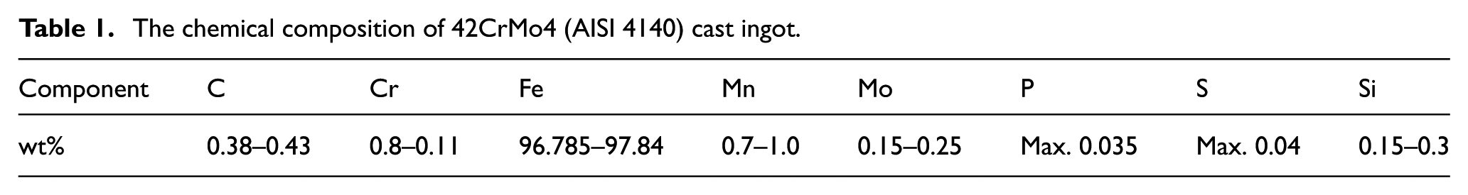
Figure 1 shows the hot flow stress measured under different experimental conditions. The measured flow stress data allowed the hot deformation behavior of the cast structure to be analyzed by finite element analysis.
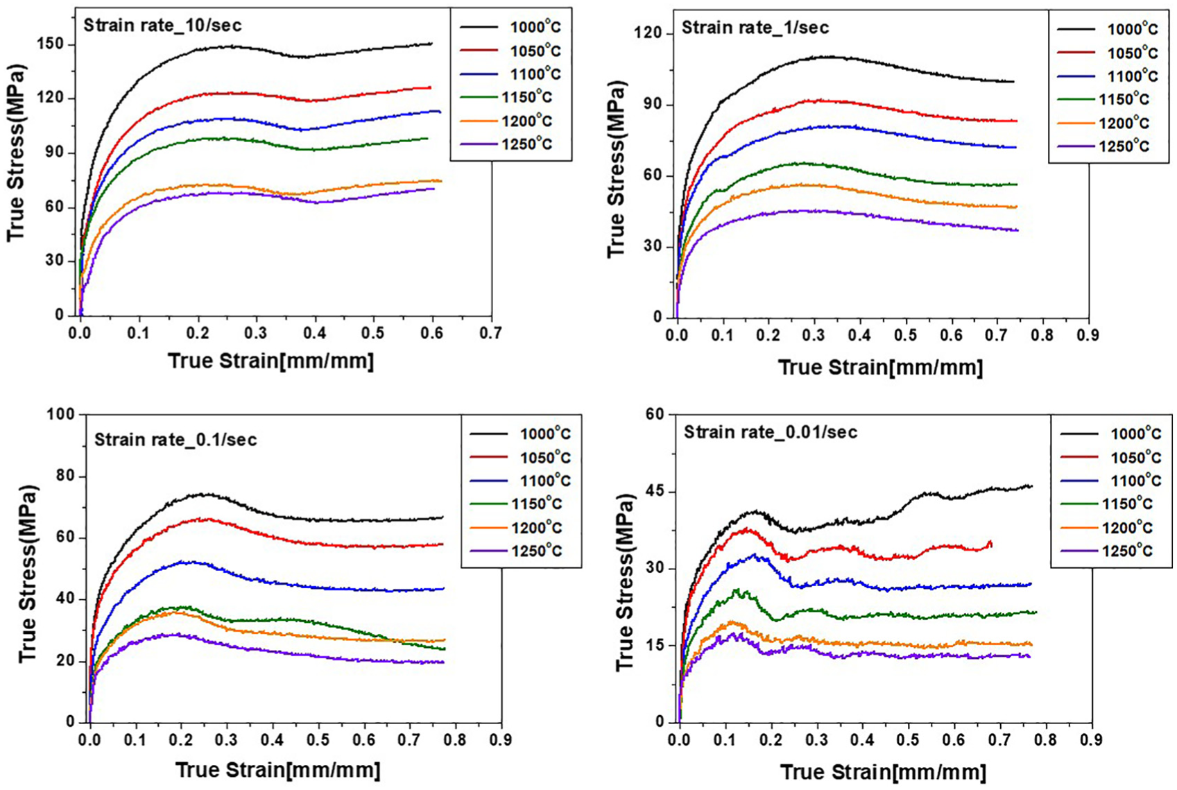
Flow stress measured by hot compression test of AISI 4140 cast ingot.
Cavity defect analysis
This section describes the analysis of the causes of cavity defects in forged products including cavities with a diameter of about 4% of the outer diameter of the ingot. The internal defects of forged products are generally examined by ultrasonic inspection, a nondestructive method, in the length and diameter directions. The ultrasonic thickness measurement showed that 500-mm-long defects with sizes from Ø10 to Ø20 were distributed at distances between 200 and 400 mm from the ingot surface. The positions of the defects indicated that large cavities included in the ingot body remained even after forging. The defect material was 42CrMo4 (AISI 4140), and the weights of the forged products were 22 and 18 tons. The cavity part of the forged product manufactured from the 22-ton-ingot (Case 1) was sectioned with a band saw for visual and microscopic observation, as shown in Figure 2. The microscopic investigation results, shown in Figure 3, indicate that the cavities included in the mold structure were not closed during the hot free-die forging process. The area around the cavities looked darker than the surrounding area because the ratio of cementite was high, due to carbon segregation. Scanning electron microscopic (SEM) images showed columnar crystals, which are cast structures.
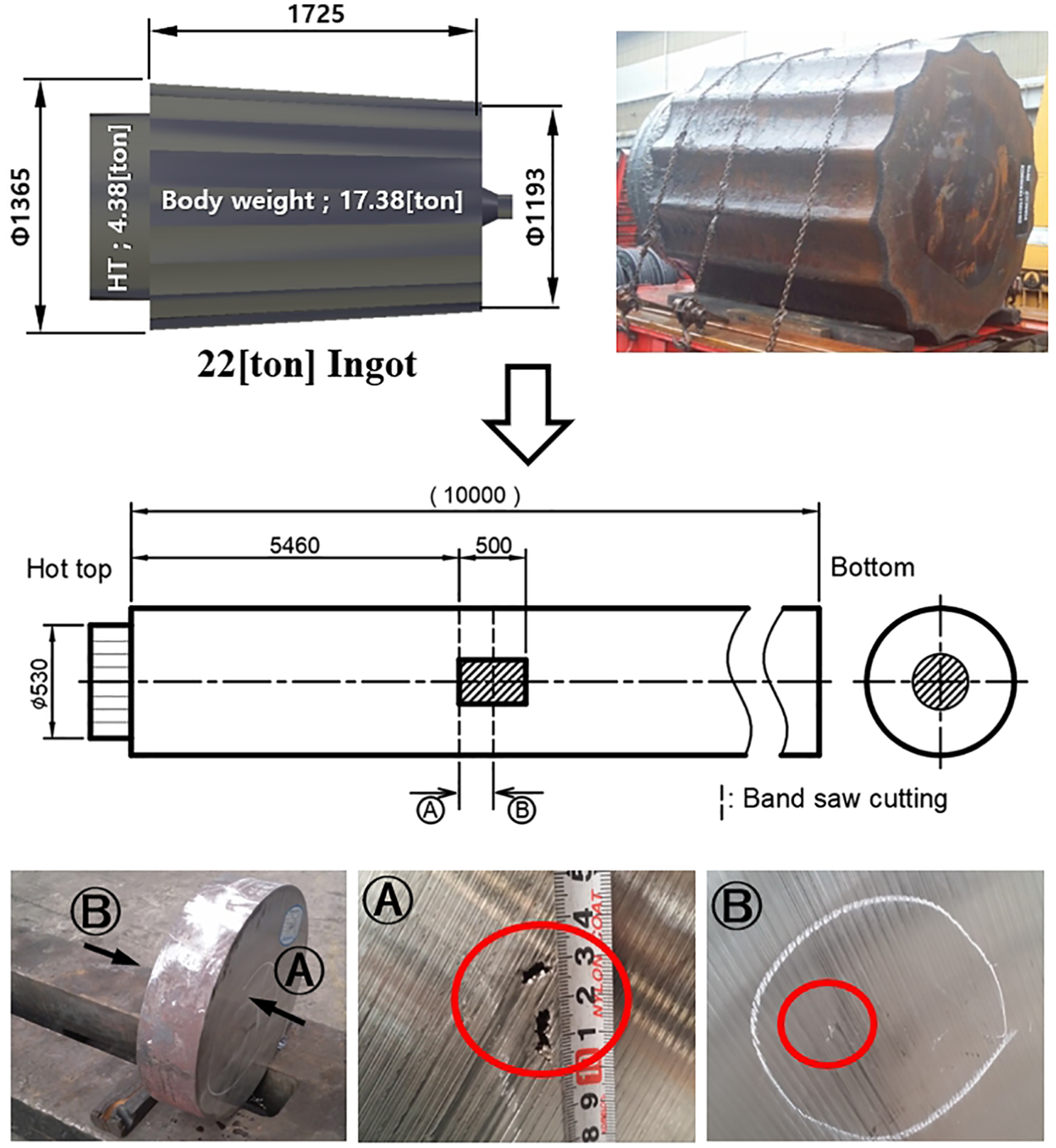
The 22-ton steel ingot specifications and visual inspection results.
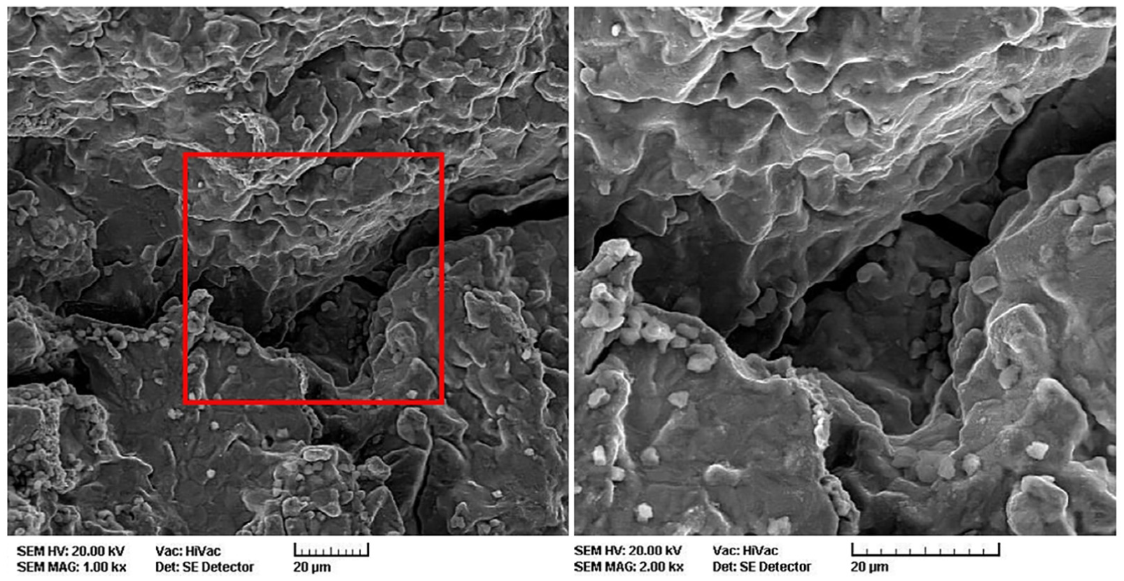
SEM images.
Defects might have been generated in the forged product manufactured with the 22-ton-ingot because large cavities in the initial material remained despite application of forging ratios of 3S or higher.
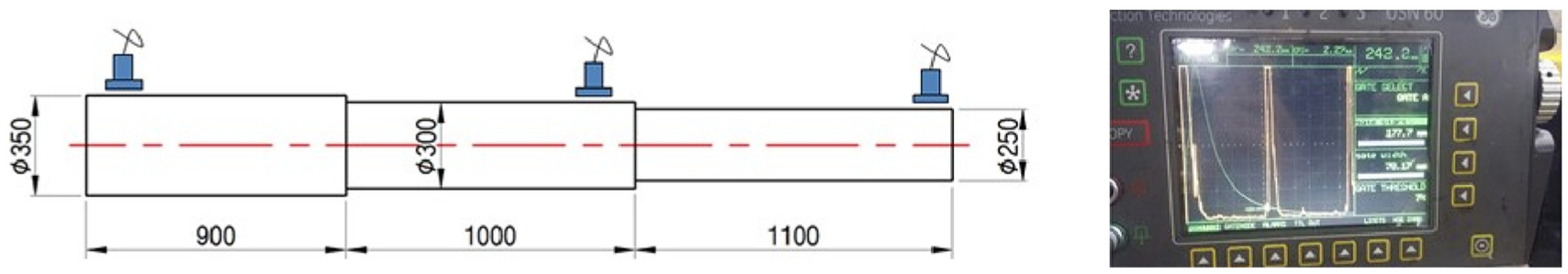
The ultrasonic tests also showed the presence of 240-mm-long defects with sizes from Ø10 to Ø20 at distances between 200 and 400 mm from the surface of the 18-ton-ingot from the same manufacturing lot number (Case 2). Figure 4 shows the positions and the waviness of the defects. The defect in Case 2 was also sectioned, as shown in Figure 4, and cogging was performed with the sectioned part to examine cavity closure. A finite element analysis was performed to examine whether the same cavity closure behavior was observed.
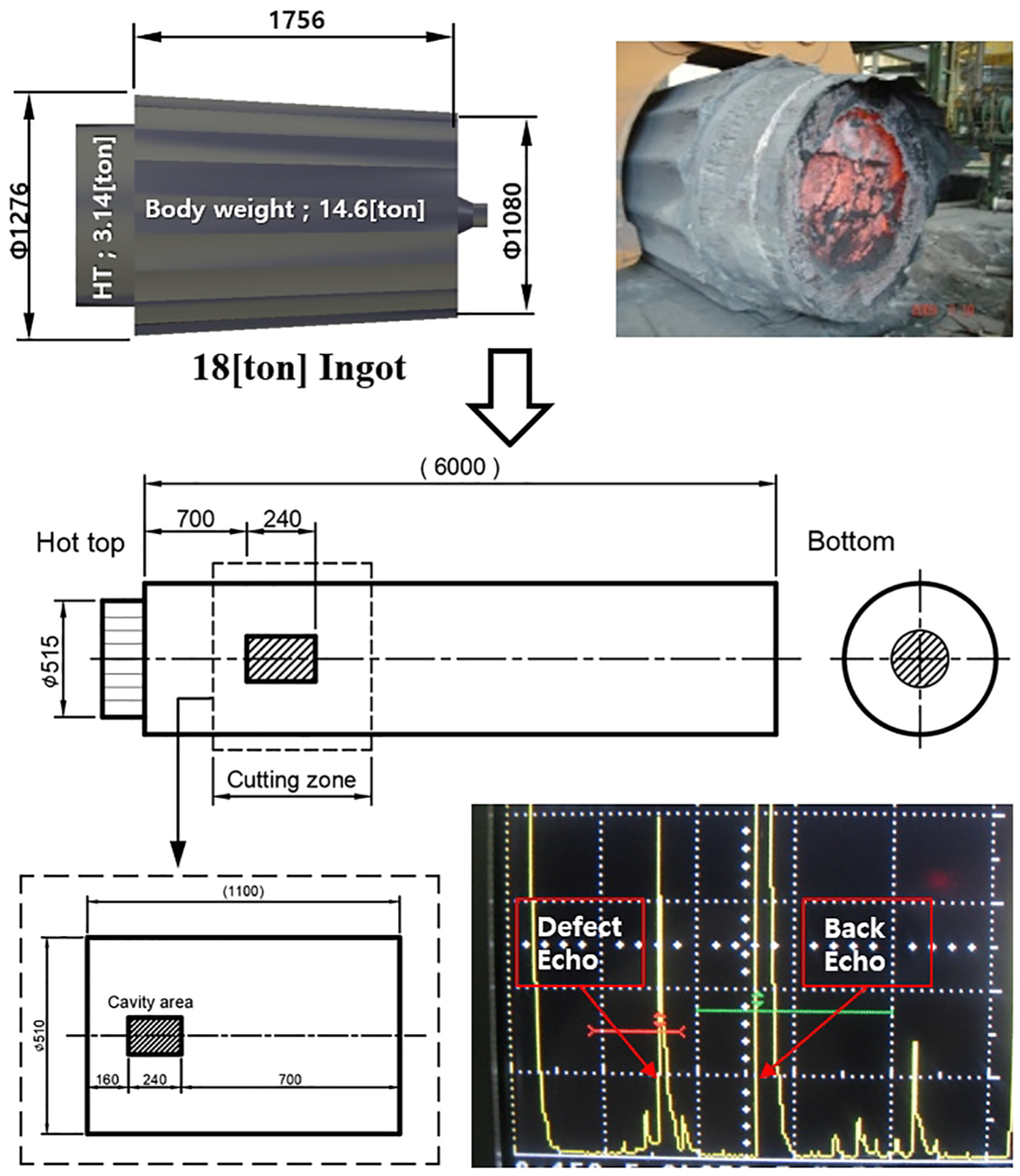
The 18-ton steel ingot specifications and UT inspection results.
Cogging process test
Next, a cogging process test was performed with the forging material, including connected defects in the core part, to empirically investigate cavity closure behavior. The material used in the test was prepared by cutting the forged product including the defects shown in Figure 4 into a size of Ø510×1100L.
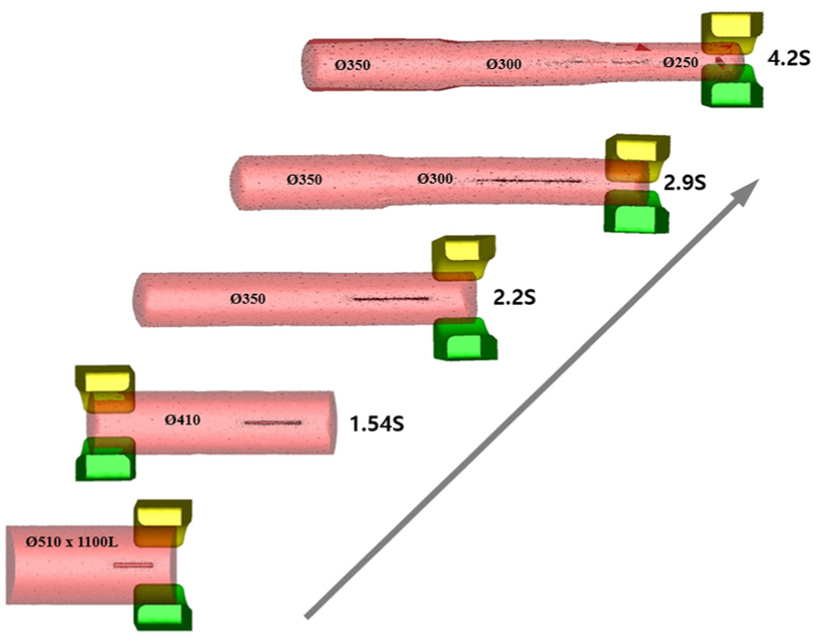
The cogging process was performed at an initial heating temperature of 1230 °C, height reduction of 50–100 mm, and a length direction movement of 150–200 mm using the R-shape mold with the die velocity of 100 mm/s. To analyze the cavity closure at different forging ratios, the forging ratio was varied at different parts in the forming, as shown in Figure 5, and then the internal defects were examined by ultrasonic inspection.
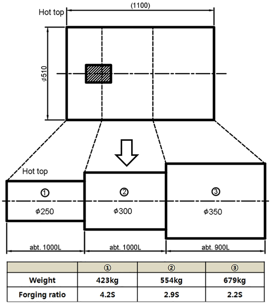
The shape design of the final forged part depending on the forging ratio.
Table 2 shows the forging path schedule for forming forged products with steps. In the cogging test, the distance moved in the length direction after Path 1 was 200 mm initially and then 150 mm after the shape was changed. The height reduction rate of the cast was 40 mm/s. The Billet rotation angle refers to the angle at which the material is gradually rotated to form a circular cross-section.
The forging path schedule during the cogging process.
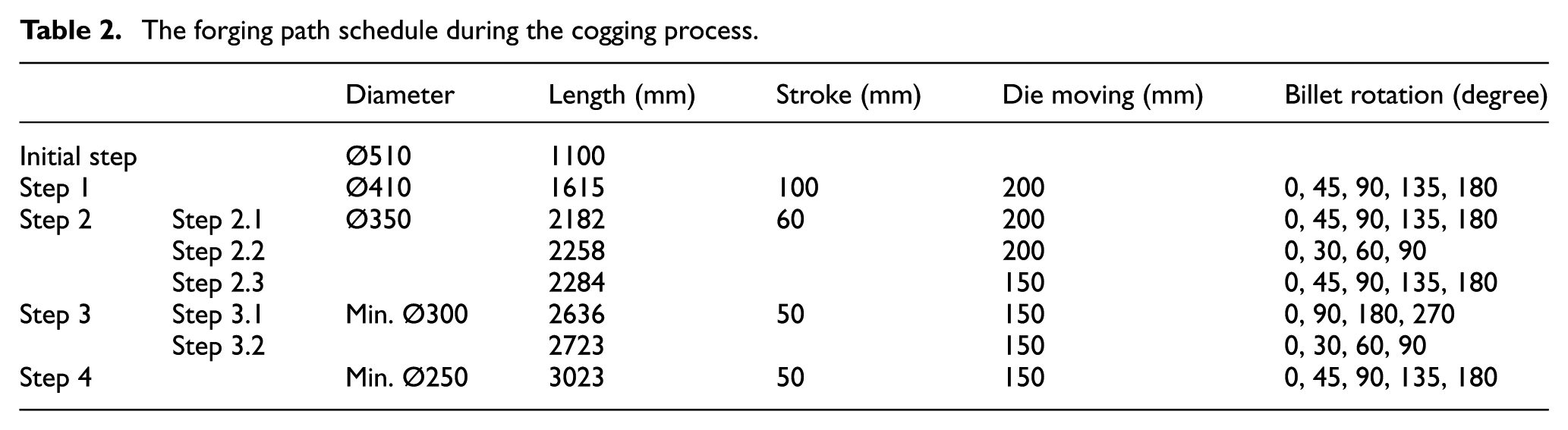
Figure 6 shows the final forged products formed using the process parameters shown in Figure 5 and Table 2. The internal soundness of the forged products was examined by ultrasonic inspection. As shown in Figure 7, the forging procedure resulted in closure of the remaining cavities.
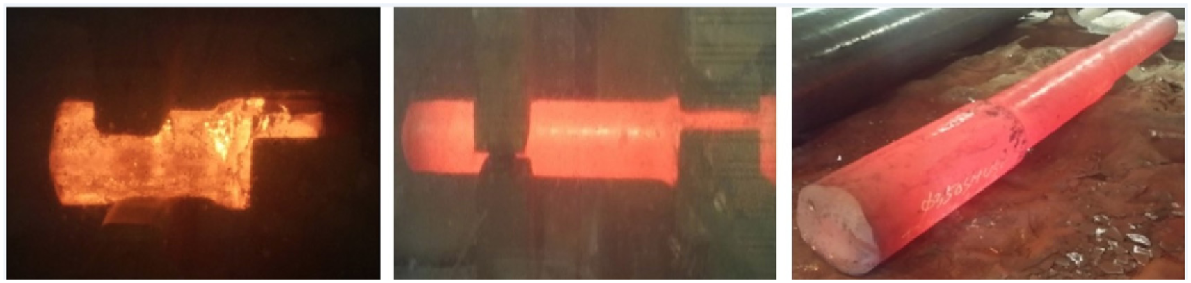
The prototype manufactured by the cogging process.
Prototype UT results.
Therefore, the experiment showed that the closure of internal cavities existing in forged products can occur if appropriate forging ratios, casts, and internal strain are applied. As shown in Figure 5, the cavities with diameters of about 4% of the outer diameter of the ingot located in the 240-mm interval were closed at a forging ratio of 2.9S or higher by the hot free-die forging process.
Finite element analysis of cavity closure behavior
Finite element model and finite element analysis of the cogging process
As shown by the ultrasonic inspection, cavity closure occurred for cavities having a diameter of about 4% of the outer diameter of the ingot at a forging ratio of 2.9S or higher when the product with the cavity defects was re-forged. Section “Finite element model and finite element analysis of the cogging process” describes the finite element analysis that was performed to provide a theoretical basis for the commonly applied 3S forging ratio and to quantitatively analyze the criteria for cavity closure (forging ratio, effective strain, and hydrostatic stress).
Figure 8 shows the forging conditions and the finite element analysis model before and after forging. The material with an initial size of Ø510 × 1100 mm was elongated to about 3000 mm after the cogging process. As shown in Table 2, the same forging conditions, including the forging height reduction path and pressing rate, were applied.
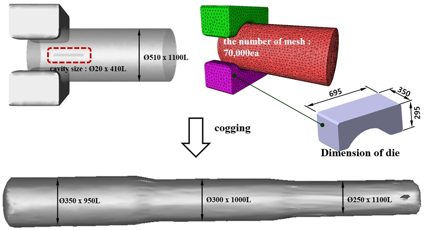
The numerical simulation model and conditions for the cogging process.
A rigid visco-plastic finite element analysis was performed with a rigid visco-plastic model and a rigid body cast to quantitatively predict the hot cavity deformation behavior. The software program used for the analysis was FORGETM-2011, a commercial finite element analysis program. The calculation was performed with a cogging template, and the number of material elements applied to the analysis was about 70,000.
The result of the analysis showed that the shape of the product was dependent on the forging ratio and that cavities initially existing in the product were elongated with the deformation of the product, as shown in Figure 9.
The numerical simulation model and conditions for the cogging process.
Deformation behavior of cavities
The amount of cavity closure at each stage of the external product deformation during the cogging process was determined by analyzing the change in cavity volume depending on the forging ratio. Figure 10 shows the quantitative analytical data for the variations in product size, cavity size, and cavity volume during the cogging process. In Step 1, where the forging ratio of 1.54S was applied, the cavity volume was increased by 65% from the initial volume. Cavity size, measured in units of 50 mm on the cavity cross-section, was Ø10 on average, indicating that the diameter was reduced by about 50% from the initial cavity size of Ø20. In Step 2, where the forging ratio of 2.2S was applied, the cavity volume was 0.003 m3, indicating that the initial cavity volume was decreased by 95%. The average diameter measured was Ø0.56, which suggests that more than 98% of the total cavity volume was decreased. In the final step where the forging ratio of 4.2S was applied, the cavity was closed so much that the cavity volume could not be measured. The analytical results showed that the length of the cavity was 750.77 mm, indicating that the initial length (240 mm) more than tripled.
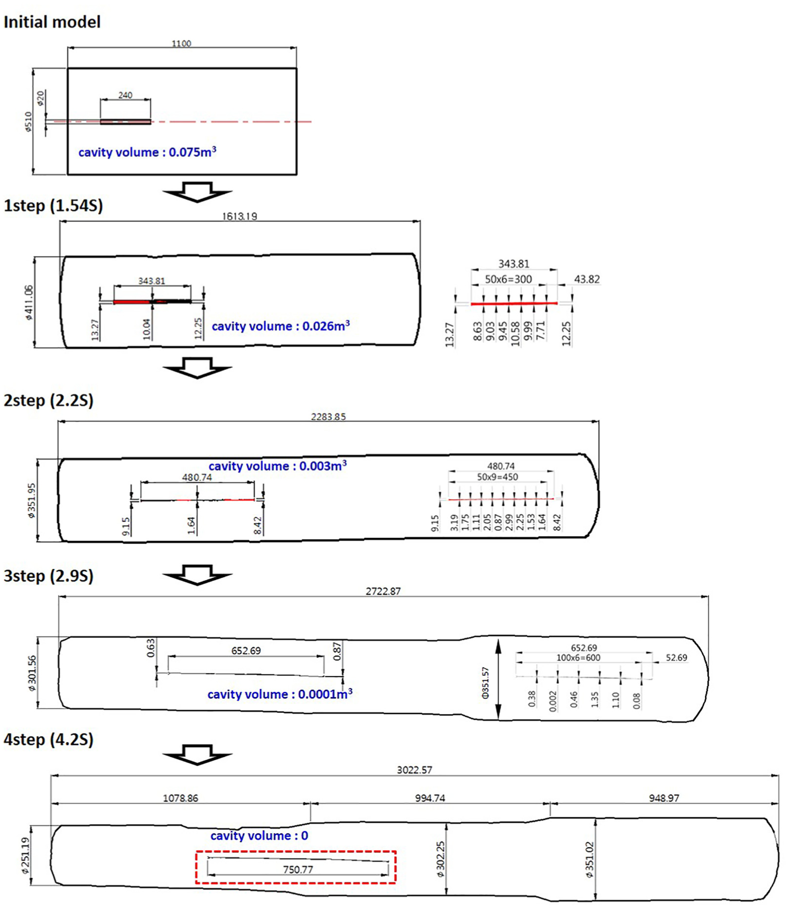
Dimensional changes in the product and cavities during the cogging process.
Figure 11 is a plot showing the changes in cavity volume during the cogging process depending on the forging ratio. As described above, cavity closure was found at a forging ratio of 2.9S or higher, which was consistent with the experimental results.
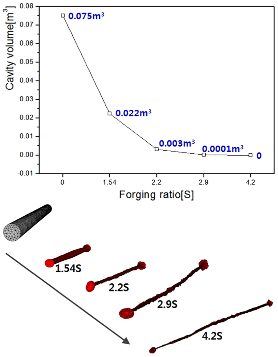
Volume changes in the cavity depending on the forging ratios.
Parameter evaluation of cavity closure mechanism
The variation in effective strain and hydrostatic stress, which is suggested to be the basis for cavity closure in forging processes, was analyzed during the progression of the forging process to determine the parameters for the cavity closure mechanism and quantify their limiting values.
Figures 12 and 13 show the change in effective strain and hydrostatic stress, respectively, during the cogging process. To analyze the effective strain and hydrostatic stress, analytical results around the cavity were measured during the forging process through point-tracking at a total of five points. Among the five points, P1 and P5 were located at both ends of the material in the length direction, P3 at the center, P2 at a position 43 mm away from the center to the P1 direction, and P4 at a position 74 mm away from the center in the P5 direction. When formation was performed, the initial five points were moved by the elongation of the material during the cogging process, and the gaps between the points increased to more than 100 mm.
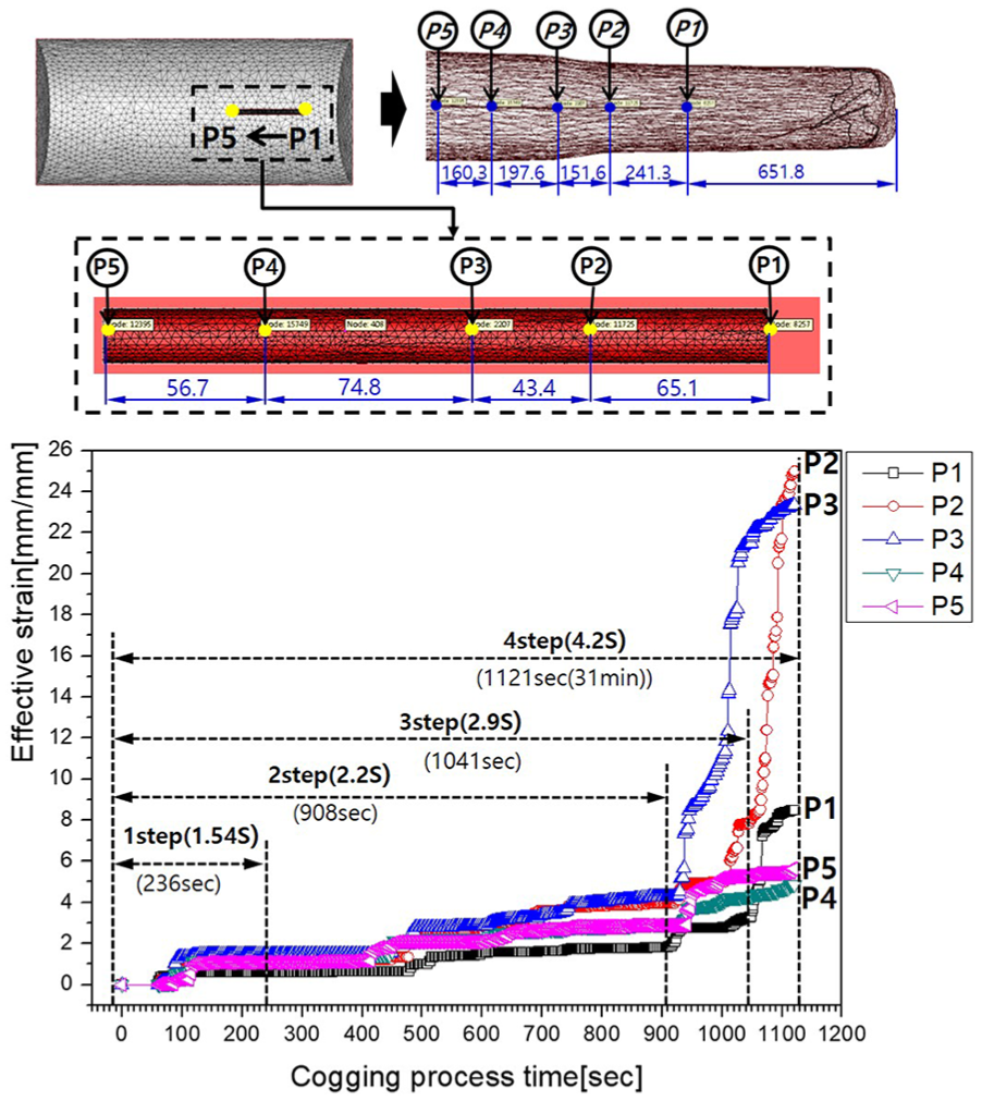
Effective strain measured at five points during the cogging process.
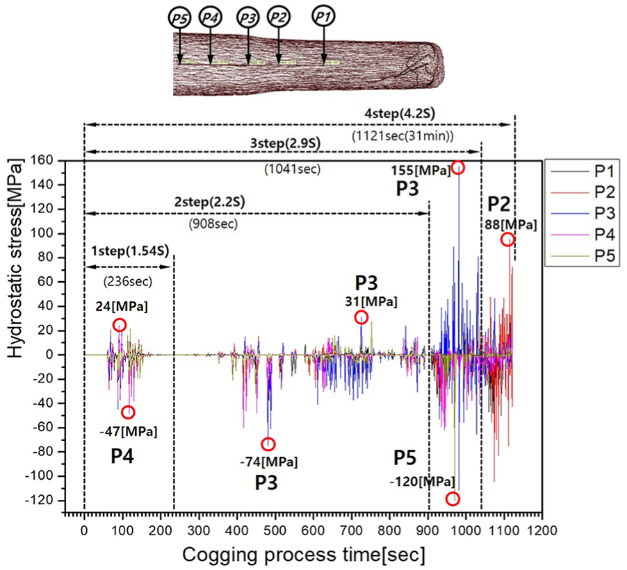
Analysis of hydrostatic stress on the five points during the cogging process.
The measurement of the effective strain measured at the five points indicated that the strain increased as the forging ratio was increased. Accordingly, the cavity was elongated in the length direction, while the cavity size and volume decreased. Cavity closure was found in the experiment performed at a forging ratio of 2.9S. The finite element analysis showed an effective strain of 3.2 at P1, where the effective strain was smallest among the five points.
Therefore, from P1 to P5, the smallest effective strain of 3.2 was measured at the point where the forging ratio of 2.9S ended. This shows that the threshold effective strain for cavity closure at the measurement point was 3.2.
In addition to effective strain, hydrostatic stress was also measured at the same five points. The plot of hydrostatic stress in Figure 13 shows that the stress values measured at the five measurement points were not consistent for repeated applications of forging load, suggesting that hydrostatic stress cannot be used as a criterion for cavity closure. However, the results showed that tensile stress and compressive stress greatly increased at forging ratios over 2S.
Threshold effective strain of cavity closure
In normal forging processes, the presence of a cavity may not be known until nondestructive inspection is performed. Therefore, in this section, effective strain was calculated in the presence and absence of a 240-mm-long cavity under the same forging conditions, and the threshold effective strain was analyzed as a criterion for cavity closure. Figure 14 shows the critical threshold effective strain values of cavity closure. The effective strain was measured in the final stage at the center of the diameter at intervals of 20 mm over the 3000-mm length, between the 4.2S forging ratio end and the 2.2S forging ratio end. With regard to the smallest strain at a forging ratio of 2.9S, the threshold effective strain was 2.9 when a cavity was present and 2.1 when it was absent.
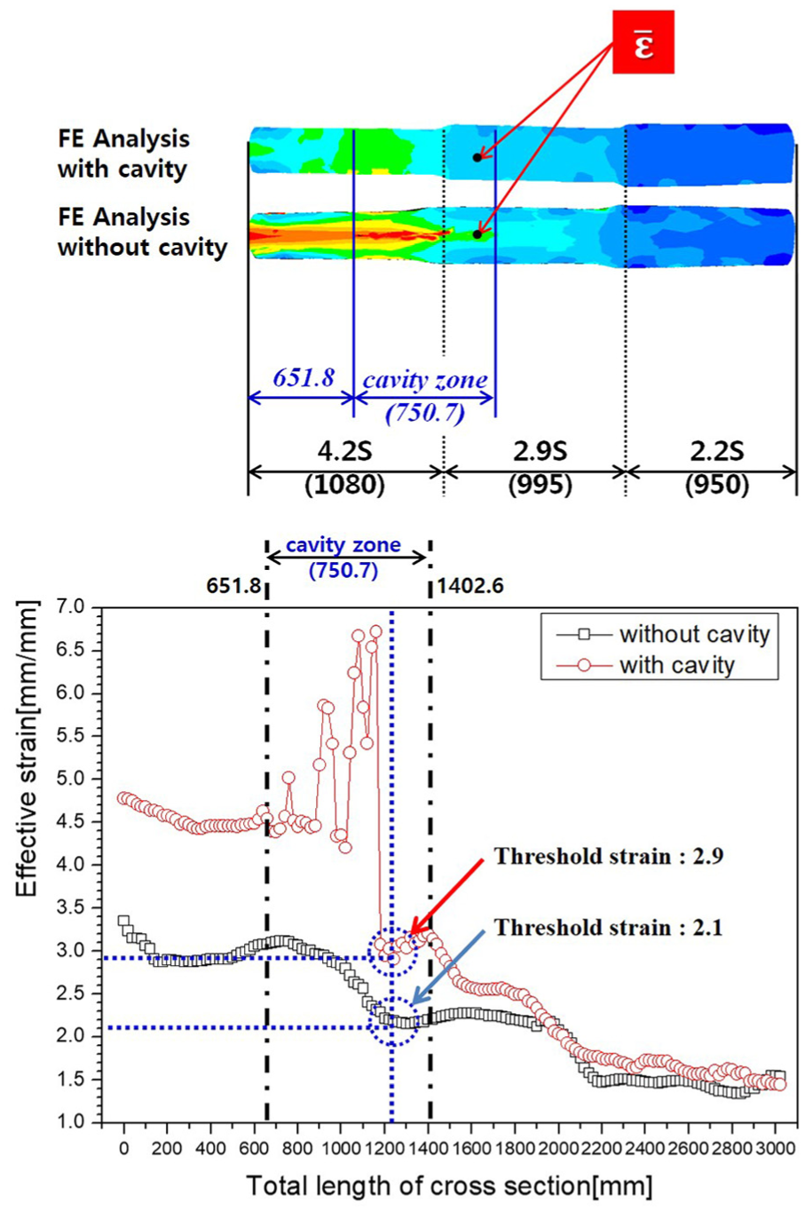
The measured threshold effective strain of cavity closure.
Since process design and optimization in industry are performed using a cavity-free model, cavity closure in steel forged products can be expected if the final threshold effective strain is equal to or higher than 2.1 and the forging ratio is equal to or higher than 2.9S in the analysis of the cogging process. A cavity defect found under the aforementioned conditions may indicate that a large cavity, with a diameter of more than 4% of the outer diameter of the initial material ingot, may have been produced inside the initial material and may have not closed during the forging process.
Conclusion
In this study, cavity closure behavior in steel ingots during a hot free-die forging process was analyzed, and the occurrence of cavity closure was inspected. In addition, changes in the height reduction ratio, forging ratio, internal strain, and hydrostatic stress were evaluated in relation to cavity closure to obtain the following conclusions:
To obtain theoretical evidence about the forging ratio employed by industry, a forging ratio above 3S, forging ratios of 2.2S, 2.9S, and 4.2S were applied to a large ingot where non-closed cavity defects were present even after a cogging process. The forging process was carried out to examine the occurrence of cavity closure at the forging ratio of 3S. The experimental results showed that a connective cavity defect with a diameter of over 4% of the outer diameter of the ingot with a size of Ø20 × 240 mm was closed at the forging ratio of 2.9S. However, internal soundness can only be ensured at a forging ratio of 2.9S when the internal cavity defect has a diameter smaller than 4% of the outer diameter of the ingot.
To obtain theoretical evidence about the minimum forging ratio required for cavity closure, a finite element analysis was performed at different forging ratios, analyzing cavity closure and changes in cavity shape and volume. Like the experimental results, the closure of existing cavities in the finite element analysis was found to occur at a forging ratio of 2.9S or higher. This means that the occurrence of cavity closures in an initial material containing defects of a known size can be precisely predicted using finite element analysis.
In the finite element analysis performed by modeling an initial material with cavities, a drastic increase in effective strain was found at the point of cavity closure, indicating that effective strain may be used as a critical threshold parameter for cavity closure. In contrast, hydrostatic pressure was not consistent under repeated applications of forging load, suggesting that hydrostatic pressure may not be an appropriate parameter for cavity closure.
Since internal defects are known to occur in initial materials at actual industrial sites, the effective strain at the cavity closure area was analyzed by performing a finite element analysis in the presence and absence of a cavity. In the presence of a cavity, the threshold effective strain at the point where the forging ratio was 2.9S was 2.9, which means that cavity closure occurred. In the model where the initial material did not have a cavity, the effective strain measured at the same position was 2.1. Therefore, in the forging process design with a cavity-free model, forged products will not contain cavities if the threshold effective strain is equal to or higher than 2.1 and the forging ratio is equal to or higher than 2.9S in an ingot having a cavity with a diameter of about 4% of the outer diameter of the ingot.
Footnotes
Declaration of conflicting interests
The author(s) declared no potential conflicts of interest with respect to the research, authorship, and/or publication of this article.
Funding
The author(s) disclosed receipt of the following financial support for the research, authorship, and/or publication of this article: This work was supported by the Korea Institute of Energy Technology Evaluation and Planning (KETEP) and the Ministry of Trade, Industry & Energy (MOTIE) of the Republic of Korea (No. 2017 3030 024670).