
Abstract
The residual stress of multi-rivet structures is related with the riveting sequence, the rivet pattern, and the pitch due to the deformation interaction of different rivets. The stress amplitude of riveted structures subjected to the cyclic loads is affected by the residual stress, which increases the difficulty in the prediction of fatigue life. In this article, the riveting processes for single-row and triple-row riveted lap joints with various riveting sequences, rivet patterns, and pitches are studied numerically and experimentally. The residual stresses for both types of riveted structures are verified by the testing data. Significant difference appears in the residual stress field for riveted lap joints with various riveting sequences and rivet patterns. The decrease in the rivet pitch increases the compressive residual stress at the edge of the rivet hole. Furthermore, the fatigue life prediction model is developed for multi-rivet structures, in which the coupling effect of residual stress and cyclic load is considered. The fatigue experiments are conducted for riveted lap joints with various riveting sequences, rivet patterns, and pitches. The accuracies of the numerical results obtained from the Homan model and the developed model are compared with the experimental data. The proposed fatigue model shows better performance to predict fatigue life for multiple rivet structures.
Introduction
The riveted lap joint is one of the most common failure sources in the aircraft.1,2 The riveted structure, used in the modern commercial aircraft, is subjected to the loading from pressurization of fuselage. The ground-air-ground pressurization cycle loads provide one major cycle of fatigue loading on the riveted structure in the airframe. In addition, the residual stress induced by the riveting process significantly influences the fatigue behavior of riveted lap joints. 3 Skorupa et al. 4 concluded that the local stress amplitude at the critical location of a joint determined the fatigue life, which is influenced by several quantities corresponding to the rivet squeeze and friction on the faying surface of a riveted joint during cyclic loading. Thus, the fatigue life of riveted structures is determined by the coupling effect of residual stress in manufacturing process and external loads including the quasi-static load and the cyclic load. This coupling effect would increase the complexity of local stress field around the rivet holes. The accurate description of the stress distribution around the rivet hole is critical for improving the prediction accuracy of the fatigue life of riveted lap joints.
Distortion and fracture of riveting are the main factors that could influence the performance of the assembled airframe. 5 The residual stress induced by the riveting process is an indispensable concern in the study of the fatigue behavior of riveted structures. Fatigue cracks are easily initiated on the hole surface due to the stress concentration in service. 6 However, larger compressive residual stress induced by higher squeeze force shifts the location of crack nucleation away from the surface of the rivet hole. 7 Thus, a great deal of interest has been focused on the residual stress induced by the riveting process in recent years. Elajrami et al. 8 presented the results of three-dimensional finite element (FE) simulation of double cold expansion process in the opposite direction. The residual stress distribution in rivet hole of aluminum alloy Al2024T3 induced by tapered pin was analyzed. The results showed that the residual stresses varied through the material depth. The maximal stresses were in the mid-depth, which were strong at the exit face and moderate at the entrance face. Li et al. 9 conducted the riveting process with strain gauges mounted on the sheet surface to capture the strain variation of riveted specimens with different squeeze forces. An accurate three-dimensional numerical technique was developed to study the residual stress and strain during the loading history. The numerical results had good agreement with the experimental data in both the riveting process and tensile loading stage that is useful for accurate prediction of residual stress at the interface of joints. Zhang et al. 10 proposed a quantitative variation propagation modeling method, in which the subsequent impact of initial residual stress in raw material was taken into account. An effective pattern mapping method between bulk stress fluctuation and overall component or assembly deformation could be obtained. Rans et al. 11 employed a three-dimensional FE model to obtain the residual stress field of riveted joints with universal and countersunk rivets. Aman et al. 12 numerically studied the effect of several controllable process parameters on the quality of riveted lap joints. Chen et al. 13 investigated a lower protrusion compressing method using a rivet. They concluded that the tension-shearing strength and cross-tensile strength of the joint could be increased by the compressing method, and neck fracture mode is the main failure mode. Zeng et al. 14 discussed the influence of the initial fit tolerance and squeeze force on the residual stress in the riveted lap joint. An analytical model of the riveting process was established in terms of the elasticity and plasticity theory. The results showed that the residual stresses in the plate would increase with the increasing squeeze force and initial fit tolerance. Kim et al. 15 studied the force characteristics of self-piercing riveting (SPR) to reduce the operating force. The effects of various workpiece temperatures and thicknesses as well as the mechanical properties of the SPR joints were examined. The results showed that the operating force of SPR was determined by the rivet deformation force. In addition, an increase in temperature in the structure could assist to decrease the operating force since it permits the use of softer rivets. However, little work has been performed on the correlation between the residual stress at the faying surface and the design parameters for multi-rivet lap joints, such as the riveting sequence, the rivet pattern, and pitch.
The actual riveted structures in the airframe simultaneously contain multiple rivets. The interaction between rivets influences the fatigue behavior of riveted joints. Thus, the design parameters of multi-rivet lap joints are related to the fatigue life. Smith 16 conducted fatigue experiments to study the effect of the rivet pitches on the fatigue life of riveted joint. It was found that a smaller rivet pitch may reduce the stress concentration and benefit to the fatigue life of riveted joint. Vlieger 17 presented similar experimental results that the smaller rivet pitch in a row prolonged the fatigue life of riveted specimens. Tian et al. 18 proposed a modified model for evaluating fatigue lives of multi-fastener mechanical joints, in which the normal bypass, transfer, and nominal stresses around the fattener holes were predicted under the plane stress condition. Masters et al. 19 proposed a simulation method in terms of a local/global approach, in which the distortion occurring around a single SPR is projected onto a global assembly at each rivet location. The method could predict the distortion from the joining process for the early design stages. However, the rivet hole filling is not accounted for by the proposed model. Here, the effects of design parameters, riveting sequence, rivet pattern, and pitch on the residual stress field and furthermore on the fatigue life of riveted lap joints are studied.
The prediction model of the fatigue life is mainly used for the actual joints with different geometry parameters from the reference joint. 20 In addition, the condition of the riveting process should be similar for the reference joint and the actual joint. However, the modification of the joint geometry could influence the consequence of the riveting process, especially the residual stress induced by the riveting process. 21 This makes it unfeasible to fulfill the riveting process similarity for the actual and reference design. Thus, the residual stress should be considered in the fatigue life prediction model. Cicco et al. 22 developed a new rivet element to evaluate the fatigue reliability of a riveted lap joint with a detail fatigue rating method. The model was proved to be effective and accurate for evaluation of the fatigue reliability of riveted structures. Huang et al. 23 proposed a new detail fatigue rating method to investigate the fatigue reliability of rivet lap joints of aircraft structures. The traditional detail fatigue rating model was improved and has better prediction for the fatigue reliability. Tan et al. 24 proposed a methodology that integrated wear and stress analysis to quantify the life of a riveting die. The stress distribution on the die during riveting was simulated based on a FE approach. The maximum and minimum von Mises’ stresses generated from the FE model were input into a Goodman diagram and an S-N curve to compute the life of the riveting die. The experiments were conducted to measure the applied load required to split a rivet. Seifi et al. 25 conducted experimental and numerical studies on the fatigue crack growth of hollowed pre-notched plates with multiple site damages. The effects of the thickness, the hole diameter, and the central distance of the holes on the initiation and growth of the fatigue cracks were investigated. The results showed that the distance of the holes had the greatest effects on the fatigue lives, while the diameter of the hole had little effects. Moreover, the residual stress was influenced by the distance of holes and should be considered for the prediction of fatigue life of riveted joints.
In this article, the residual stresses around the holes of simple-row and triple-row riveted structures are numerically studied with various riveting sequences, rivet pitches, and rivet patterns, which are also verified by the experimental data. Meanwhile, the maximum and minimum of stress around the holes for the structures subjected to the cyclic load and residual stress are calculated. Considering combining effect of the residual stress and the cyclic stress, a fatigue life prediction model for multi-riveted joint structures is developed and verified by fatigue experiments. The comparison between the testing data and numerical results from the Homan model and the developed model is conducted.
Numerical model for residual stress
The residual stress beneath the rivet-driven head is difficult to be measured for the riveted specimens. Thus, the numerical simulation is performed to obtain the residual stress induced by the riveting process. In addition, the remote loading is applied on the riveted specimen to analyze the local stress field.
FE model
Three-dimensional numerical models for the single-row riveted lap joints and the triple-row riveted lap joints are established. Various riveting sequences and rivet pitches are discussed in the single-row riveted lap joints. In addition, the effect of two types of rivet patterns is studied by using the triple-row riveted lap joints. Each riveted joint consists of 2.0-mm-thick Al-Li alloy sheets. The diameter of the rivet hole on the joint is 4.88 mm. Countersunk-type NAS1097AD6-6 rivets are employed in joining the sheets. The initial diameter of rivet is D0 = 4.76 mm. The riveting process of structures subjected to the remoting loads is numerically studied. The detailed simulation process is shown in Figure 1.
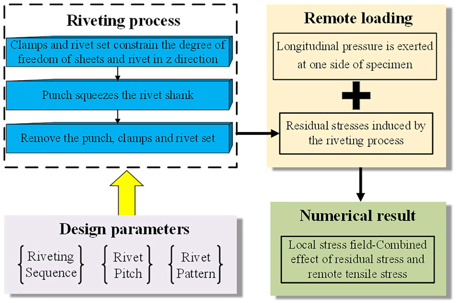
Framework of numerical simulation.
Figure 2 is the single-row riveted lap joint with punches, clamps, and rivet sets. Here, the length of sheets is L = 130 mm and the width is W = 4P, where P is the rivet pitch. Three types of rivet pitches are studied for the single-row riveted lap joints, which are 15 mm, 20 mm, and 25 mm, respectively. The ratios of the rivet pitch and the rivet diameter

FE model of single-row riveted lap joint.
The left and the right sides of the riveted specimen are fixed during the riveting process and also illustrated in Figure 2. The degree of freedom in z direction of sheets is constrained by two rigid clamps during the riveting process of each rivet. The rigid clamp is an annulus with inner diameter Did = 10 mm and outer diameter Dod = 14 mm. The rivet is also constrained in z direction by the rigid rivet set. After the riveting process, the punch, two clamps, and the rivet set are removed. This process is conducted repeatedly for the following rivets.
Figure 3 illustrates the FE models of triple-row riveted lap joints for two types of riveting patterns that are the staggered riveting and the in-line riveting. The dimensions of the sheet are 60 × 180 × 2 mm. The rivet pitch and the rivet row spacing of triple-row riveted joints are 20 mm. The boundary conditions in the triple-row riveted lap joints are the same as these in the single-row riveted lap joints.
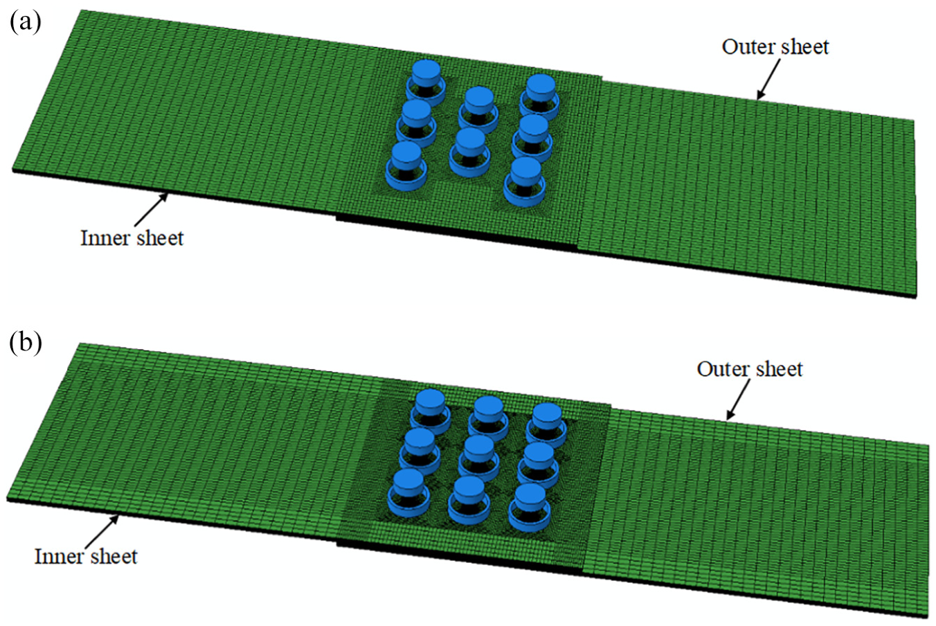
FE models of triple-row riveted lap joints: (a) staggered riveting and (b) in-line riveting.
The simulations were conducted by using the commercial software package ABAQUS/Explicit. The rivets and sheets are discretized with three-dimensional reduced-integration brick elements C3D8R. The number of nodes and elements are approximately 270,000 and 240,000 for the single-row riveted structure and 760,000 and 660,000 for the triple-row riveted structure, respectively. The general contact model that is built in the software is employed during the numerical analysis. The friction coefficient is 0.18 for all the contact interfaces. 11
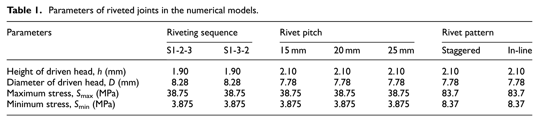
The dimensions of rivet-driven head and the cyclic loads in the numerical models are listed in Table 1. Two types of the heights of driven head are chosen according to Yuan. 26 The maximal tensile stress is determined according to the tensile testing of material for riveted specimens and is equal to 80% of its ultimate tensile strength.
Parameters of riveted joints in the numerical models.
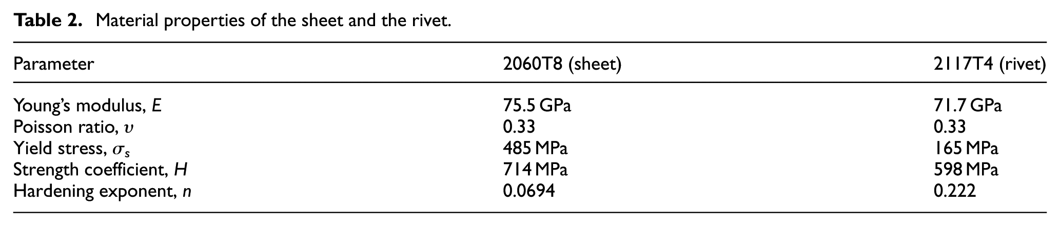
The material properties of aluminum alloy 2117T4 for rivets and Al-Li alloy 2060T8 for sheets are obtained by uniaxial tension experiments. The Hollomon constitutive model is employed to describe the stress–strain relationships of materials for sheet and rivet. The strength coefficient H and the hardening exponent n in the Hollomon model are calculated by substituting the uniaxial tensile test data into
Material properties of the sheet and the rivet.
Numerical model verification
Residual stresses on the surface of sheet may be easily determined with the experimental method. Here, the X-ray diffraction (XRD) testing was conducted by using the iXRD Combo X-ray diffractometer equipped with co-radiation. The residual stresses are measured at 11 values from −30° to 30°, using sin2 Ψ method. The residual stresses are measured on the surface of the inner sheet. Figure 4 shows the locations of measured points. In Figure 5, the numerical results and the testing data are compared for single-row riveted lap joint with rivet pitch P = 20 mm and triple-row riveted lap joint with in-line riveting. The testing data agree well with the numerical results.
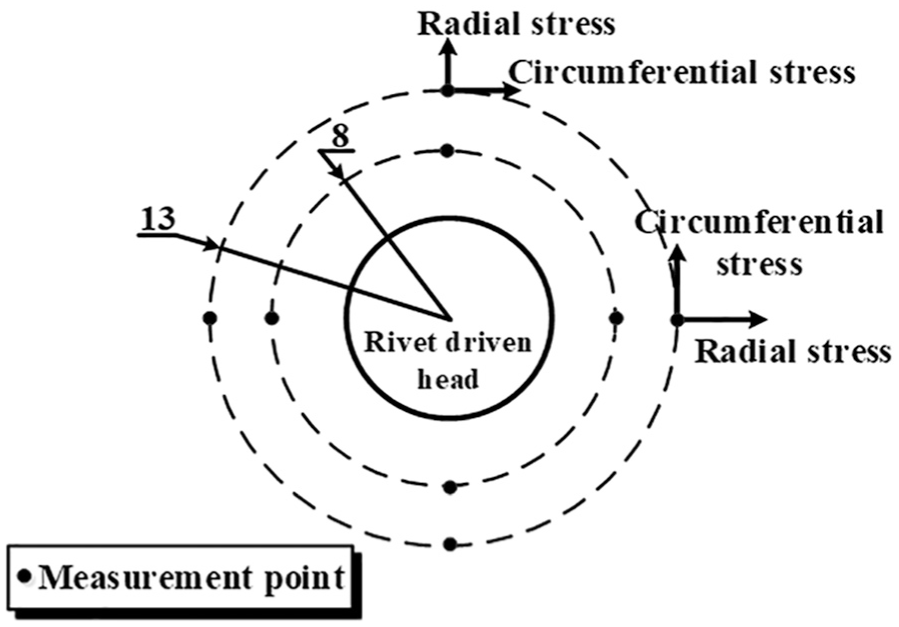
Locations of residual stress measurement.
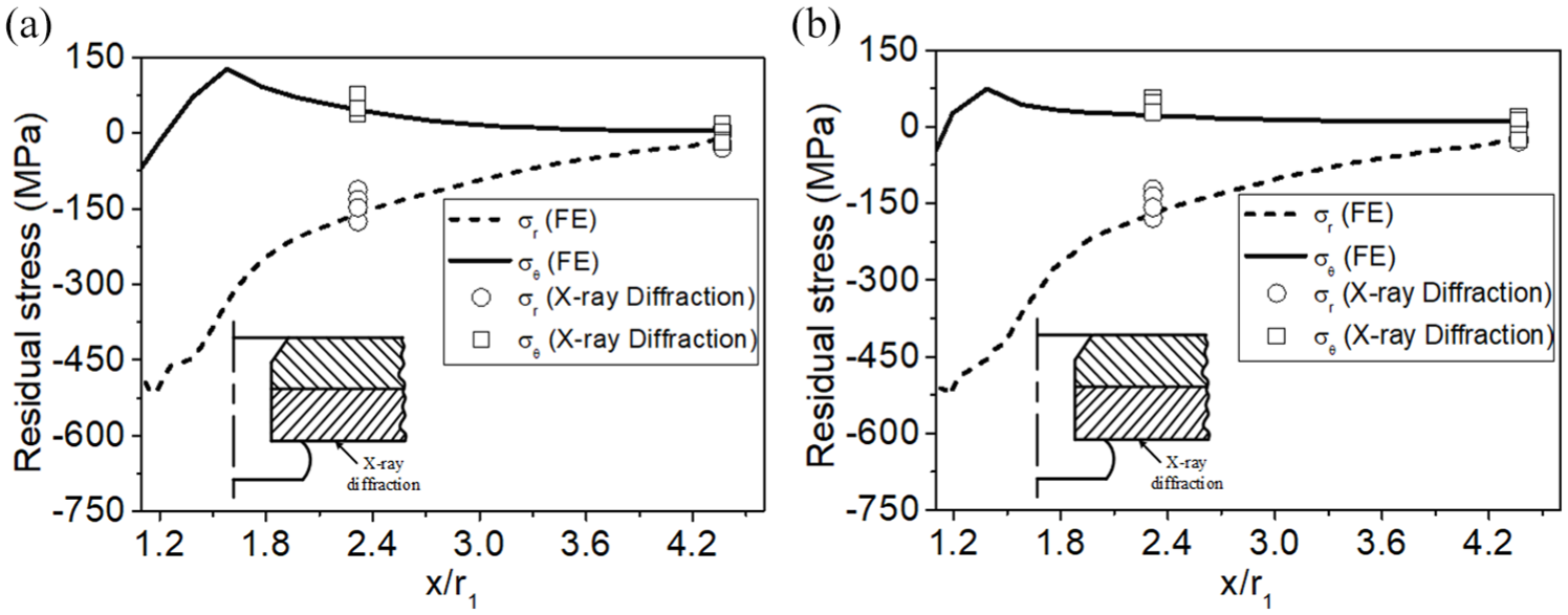
Comparison of residual stress of numerical results and testing data: (a) single-row riveted lap joint with rivet pitch P = 20 mm and (b) triple-row riveted lap joint with in-line riveting.
Residual stress of riveted joints with different parameters
The effects of the riveting sequence (S), the rivet pitch (P), and the rivet patterns on the local stress filed of riveted joints were studied. The riveting sequence is a controllable parameter in riveting process, which impacts the distribution of local stress. The rivet pitch and rivet pattern are also important design parameters for riveted joints. 27 The classifications of riveting sequences, the rivet pitches, and the rivet patterns are listed in Table 1.
Fatigue cracks tend to nucleate on the outer faying surface in the vicinity of the hole because of the adverse effect of the fretting and the tensile secondary bending.
28
The circumferential stress is of primary interest owing to its direct influence on the nucleation and the growth rate of the mode I crack that typically appears in the riveted specimen subjected to the remote tension. Thus, the circumferential stress on the outer faying surface along the radial direction is investigated. The local stresses, including the residual stress and the tensile stress, are obtained along the radial path. This path is on the minimal cross section of riveted specimens and perpendicular to the longitudinal tensile direction of the joint, as shown in Figure 6. The local stresses of the riveted joint are presented with the radial position ratio
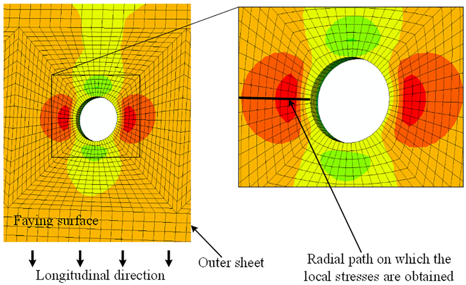
The path to obtain the local stresses.
Effect of riveting sequences
Figure 7 demonstrates the stress distributions of riveted specimens with sequences of S1-2-3 and S1-3-2. The specimen with single rivet is also employed to illustrate the interaction of the multiple rivets on the residual stress, as shown in Figure 7(a). The smaller compressive residual stress appears on the edge of the rivet hole. In addition, the peak tensile stress of the single rivet specimen is larger than other specimens with triple rivets. Thus, the interaction of the multiple rivets in the riveting process would be beneficial for improving the fatigue behavior of riveted structures. With the identical geometrical dimensions, the larger compressive residual stress appears in the specimen with the riveting sequence S1-3-2. The circumferential residual stresses at the hole edge are −160 and −240 MPa for the sequence S1-2-3 and S1-3-2, respectively. Meanwhile, the peak tensile stress induced by the sequence S1-3-2 is lower than that induced by the sequence S1-2-3. In contrast to the sequential riveting, the combined effect of the rivet 1 and the rivet 3 increases the compression between the hole surface and the rivet shank of rivet 2. Thus, the riveting sequence S1-3-2 results in the larger compressive residual stresses, which may prolong the fatigue life of the riveted structure.
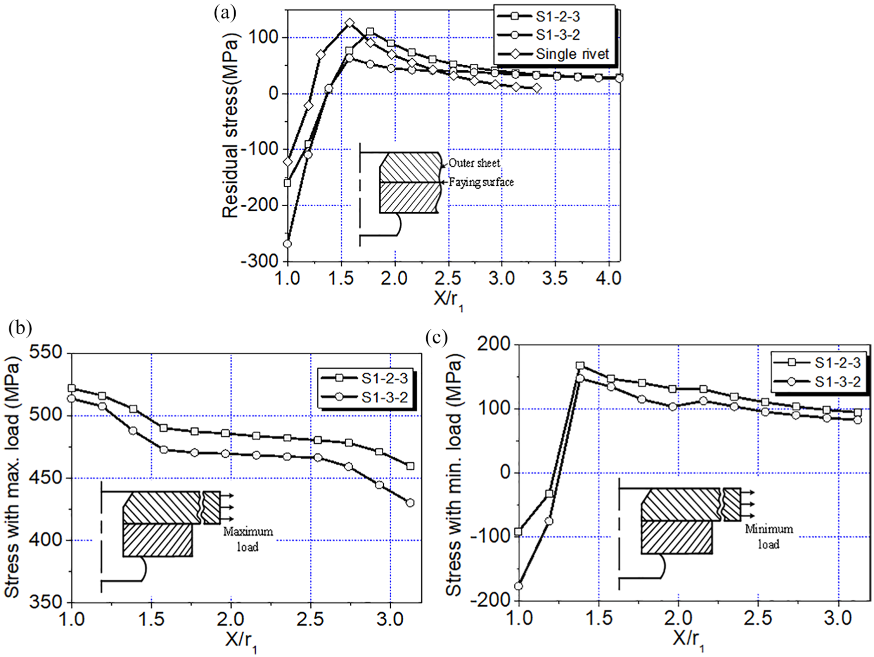
Effect of riveting sequence on the local stresses: (a) residual stress, (b) local stress induced by maximum load, and (c) local stress induced by minimum load.
The local stresses induced by the maximal and the minimal tensile loads are illustrated in Figure 7(b) and (c). The riveting sequence S1-2-3 increases the circumferential stresses induced by the maximal tensile load. The tendency of stress subjected to the minimal load is the same as the residual stress. The circumferential stress at the hole edge is still in the compressive stress state, which are −93 and −178 MPa for sequences of S1-2-3 and S1-3-2, respectively.
According to the model proposed by Homan and Jongebreur, 29 the local stress will be the same for the specimens with identical geometrical dimensions. However, the lower stress is introduced in the riveted specimen with riveting sequence S1-3-2, as shown in Figure 7(b) and (c). This discrepancy is attributed to the reason that the residual stress induced by the rivet expansion is not considered in the fatigue life prediction model. The local stress field of riveted structure is influenced by the combined effect of the residual stress and the remote tensile stress.
Effect of rivet pitch
The rivet pitch is an important parameter that has a remarkable effect on the fatigue behavior of the riveted structures.12,26 Here, the single-row riveted specimens with various rivet pitches are studied, including P=15 mm, P=20 mm, and P = 25 mm. These rivet pitches are commonly used in the actual riveted fuselage structures. 26 The circumferential residual stresses on the outer faying surface are shown in Figure 8(a). The gray region in Figure 8 is enlarged and presented at the right side. At the edge of the rivet hole, the compressive residual stress of riveted specimen increases with the decrease in rivet pitch. The circumferential residual stresses at the hole edge are −154, −111, and −101 MPa for the riveted specimens with P = 15 mm, P = 20 mm, and P = 25 mm, respectively.
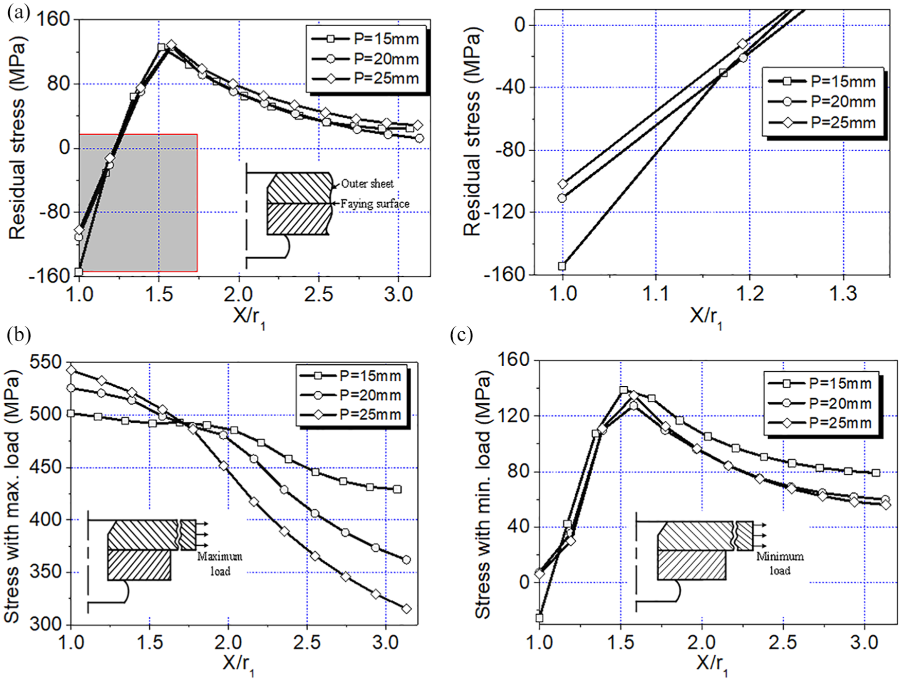
Effect of rivet pitches on the local stresses: (a) residual stress, (b) local stress induced by maximal load, and (c) local stress induced by minimal load.
The stresses induced by the maximal and the minimal loads are presented in Figure 8(b) and (c). The stresses of specimens with various pitches are close to each other in the range of x/r1 = 1.5–1.8. Larger tensile stress appears at the hole edge with the increase in rivet pitch in row. This effect may be attributed to lower compressive residual stress induced by the riveting process and more severe stress concentration caused by larger rivet pitch.
Effect of rivet patterns
Two types of rivet patterns are involved, namely, the staggered riveting and the in-line riveting, as shown in Figure 3. The circumferential residual stresses in the specimens with different rivet patterns are shown in Figure 9(a). The region and the magnitude of the compressive residual stress increase in the specimen with in-line riveting pattern. The residual stresses at the hole edge are −126 and −86 MPa for the in-line riveting and the staggered riveting, respectively.
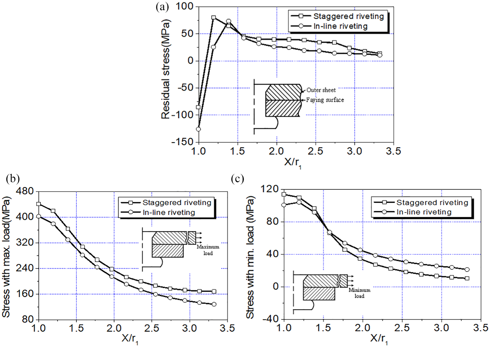
Effect of rivet patterns on the local stresses: (a) residual stress, (b) local stress induced by maximum load, and (c) local stress induced by minimum load.
The local stresses induced by the maximal and the minimal loads are shown in Figure 9(b) and (c). The circumferential stress in the riveted specimen decreases for the in-line riveting process. At the hole edge, the local stresses induced by the maximal tensile load are 483 and 402 MPa for specimens with staggered riveting and in-line riveting, respectively. The local stress distribution induced by the minimal tensile load is different from the distribution of the circumferential residual stress. The tensile stress appears at the hole edge since the applied load is high enough to cause the transition of the stress state.
The rivet patterns influence the residual stress induced by the riveting process for the variation of specimen configuration. They are also different in the local stresses due to the effect of residual stress. Thus, the residual stress is an important factor that influences the fatigue performance of multi-row-riveted lap joint.
Fatigue tests of rivet joint structures
The riveted lap joints employed in the fatigue tests are presented in Figure 10. The configuration of the single-row riveted lap joint is shown in Figure 10(a). The rivet pitches for the single-row riveted lap joints are P = 15 mm, P = 20 mm, and P = 25 mm. The triple-row riveted lap joints with different rivet patterns are presented in Figure 10(b) and (c). For the triple-row riveted lap joints, the rivet pitch in row and the rivet row spacing are 20 mm. Each riveted specimen comprised 2.0-mm-thick Al-Li alloy sheets and 2117T4 aluminum alloy countersunk-type rivets. These specimens are riveted by using the automatic riveting machine. The dimensions of rivet driven head are in accordance with those in Table 1.
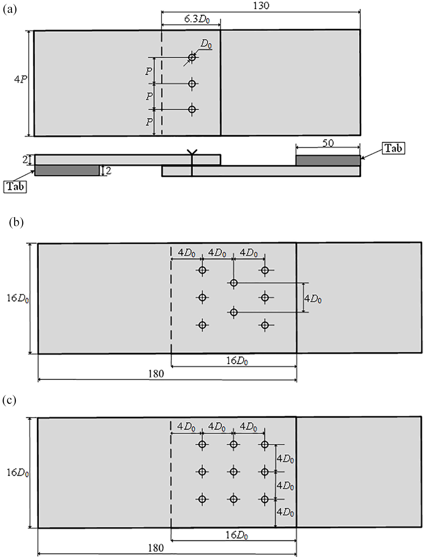
Riveted specimens in fatigue tests: (a) single-row riveted lap joint, (b) triple-row riveted lap joint with staggered riveting, and (c) triple-row riveted lap joint with in-line riveting.
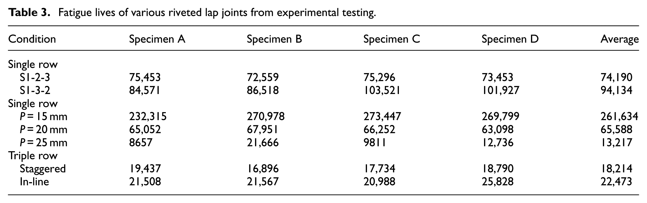
The fatigue tests are carried out with an MTS Landmark fatigue machine and shown in Figure 11. All riveted specimens are subjected to the constant amplitude loaded in tension situation. The test frequency is 10 Hz and the stress ratio is 0.1. The maximal remote stress is 38.75 MPa for the single-row riveted lap joints and 83.7 MPa for the triple-row riveted lap joints. Tabs are clamped at the ends of the specimen to ensure that the tensile load is applied on the middle surface of the riveted specimen. Four fatigue tests are performed for each condition listed in Table 1. The replicate specimens used in the fatigue tests are denoted as A–D. The testing results of riveted lap joints are given in Table 3.
Fatigue lives of various riveted lap joints from experimental testing.
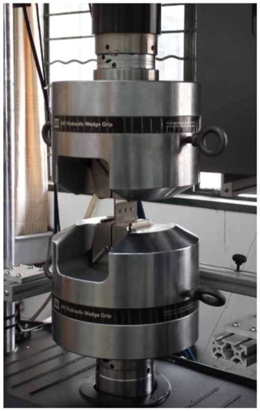
Fatigue testing equipment.
The experimental data indicate that the riveting sequence S1-3-2 increases the fatigue life of riveted lap joint, comparing with the riveting sequence S1-2-3. The riveting sequence S1-3-2 was also recommended by Aman et al., 12 who conducted various numerical simulations to obtain the optimum riveting sequence. The increase in the rivet pitch in row yields a decrease in the fatigue life of riveted lap joints. The same trend was presented by Vlieger 17 who observed smaller rivet pitch in row prolonging the fatigue life of riveted specimen. The results of triple-row riveted joint demonstrate that the staggered riveting in this context slightly decreases the fatigue life of the multi-row riveted lap joint.
Figure 12 illustrates the crack paths of riveted lap joints with various riveting sequences. The cracks initiate at the rivet hole and grow through the hole for the riveted specimen with riveting sequence S1-2-3. However, the crack path is moved a short distance from the hole edge for the riveted specimen with riveting sequence S1-3-2 because of the improved residual stress state shown in Figure 7.
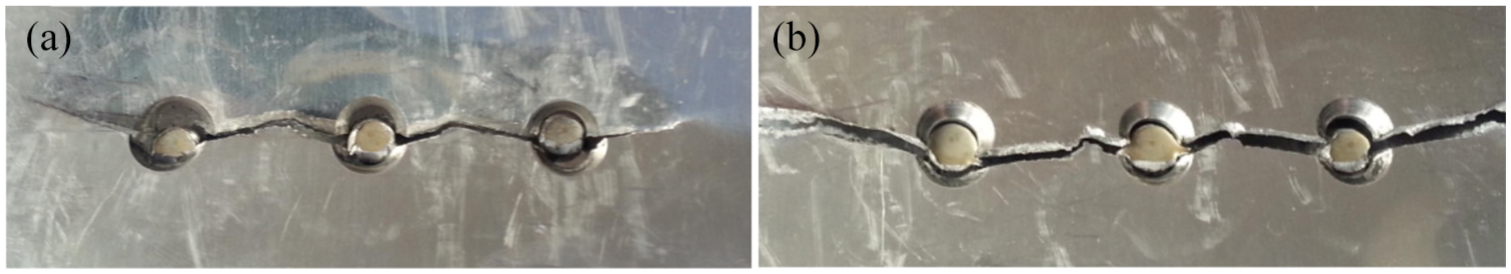
Effect of riveting sequences on the fatigue cracks: (a) S1-2-3 and (b) S1-3-2.
The effect of rivet pitches on the crack path of riveted lap joint is shown in Figure 13. With smaller rivet pitch P = 15 mm, the cracks nucleate outside the rivet hole and propagate away from the net cross section. Increasing the rivet pitch in row causes the change in crack path. The crack propagates in the net cross section for the specimen with rivet pitch P = 20 mm. For the larger rivet pitch P = 25 mm, the crack appears on the rivet, rather than on the outer sheet. The location variation of crack nucleation and propagation is the consequence of the effect of the geometrical dimension and the residual stress. Larger rivet pitch increases the stress concentration factors, which adversely affects the clamping of the riveted joint. In addition, the compressive residual stress at the hole edge also decreases with the increase in rivet pitch, as shown in Figure 8. Thus, the fatigue failure occurs at the rivet hole, even at the rivet shank.
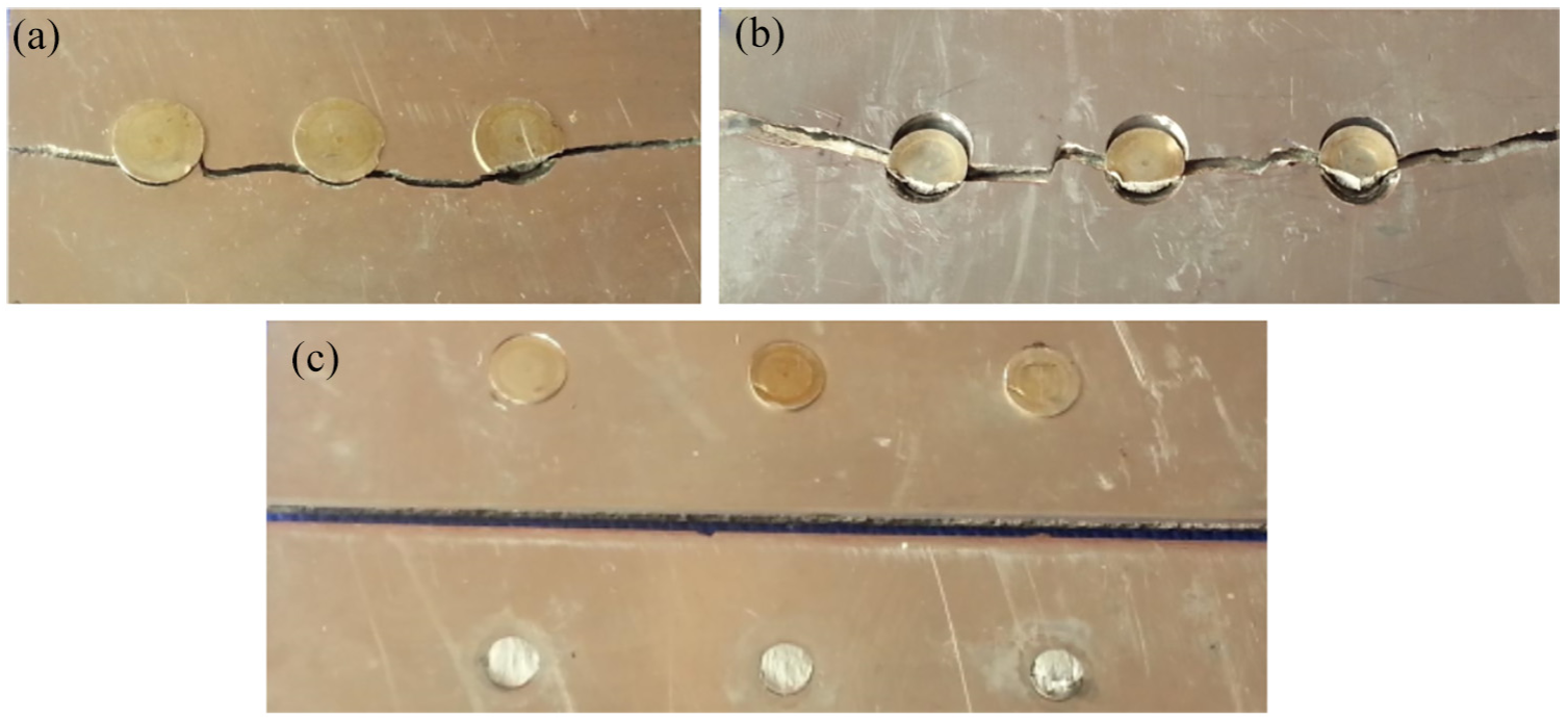
Effect of rivet pitches on the fatigue cracks: (a) P = 15 mm, (b) P = 20 mm, and (c) P = 25 mm.
Figure 14 presents the crack paths of multi-row riveted joints with two types of rivet patterns. There is no obvious difference in the crack path of each rivet for both types of rivet patterns. The cracks initiate at the rivet hole and grow through the net cross section.
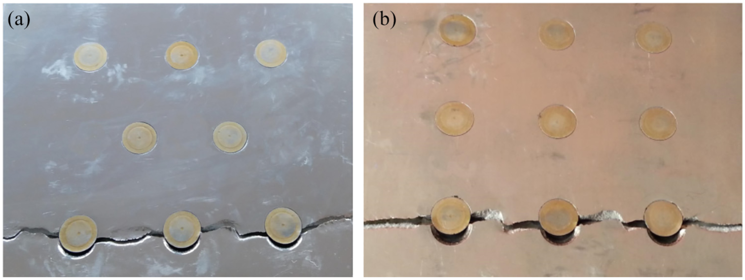
Effect of rivet pattern on the fatigue cracks: (a) staggered riveting and (b) in-line riveting.
Fatigue life prediction
The riveting patterns and pitches have effects on the local stress field of the riveted structures, including the residual stress and the tensile stress that influence the fatigue behavior of riveted structures. Here, the analytical fatigue life prediction model is developed considering both the residual stress and the tensile stress.
Fatigue life prediction model
The model suggested by Homan and Jongebreur is widely used in the fatigue life prediction of riveted joints. The fatigue life of a riveted joint is assumed to be determined by the local stress at the edge of rivet hole in the outer row. The local stress induced by the fatigue cyclic loading can be calculated as 29
where
The local stress in equation (1) is solely related to the joint geometry, which is beneficial to simplify the prediction process of the fatigue life. However, the numerical results of various riveting sequences indicate that the different local stress fields can appear for joints with identical geometrical dimensions. The reason for this discrepancy is that the residual stress induced by the riveting process is not considered in equation (1). Here, the residual stress is linearly superimposed to the stress components introduced by the applied load. This approach to predict the fatigue life of specimen with the residual stress is also employed in Clark 32 and Ball and Lowry. 33 The circumferential residual stress is of primary interest due to its direct influence on the crack nucleation and the growth rate under the remote tension loads. 5 Thus, the local stress in the outer rivet row can be calculated by superposing contributions of the applied loads and the circumferential residual stress, which is written as
where
The fatigue life of the riveted lap joint is calculated by using the S-N curve of the 2060T8 Al-Li alloy sheet with a central hole. The nominal stresses of the notched sheet are calculated in terms of the local stresses in equation (2), which are written as
where
where
According to the Walker equation, the equivalent stress amplitude
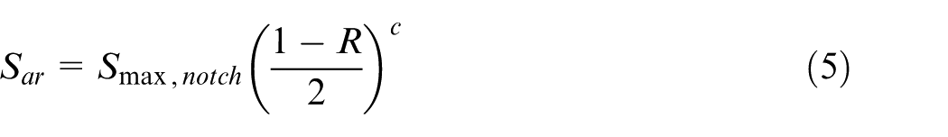
where
According to the ASTM Standard No. E466, the fatigue testing to obtain the S-N curve of 2060T8 Al-Li alloy is carried out by using the equipment in Figure 11. The data of the S-N curve for

where
Comparison of fatigue life results
The developed model is employed to predict the fatigue life of riveted specimens and summarized in Table 1. The fatigue life prediction is also done by using the model presented by Homan and Jongebreur. 29 The results from both models and the experimental data are listed in Table 4.
Comparison of fatigue life obtained from prediction models and fatigue tests.
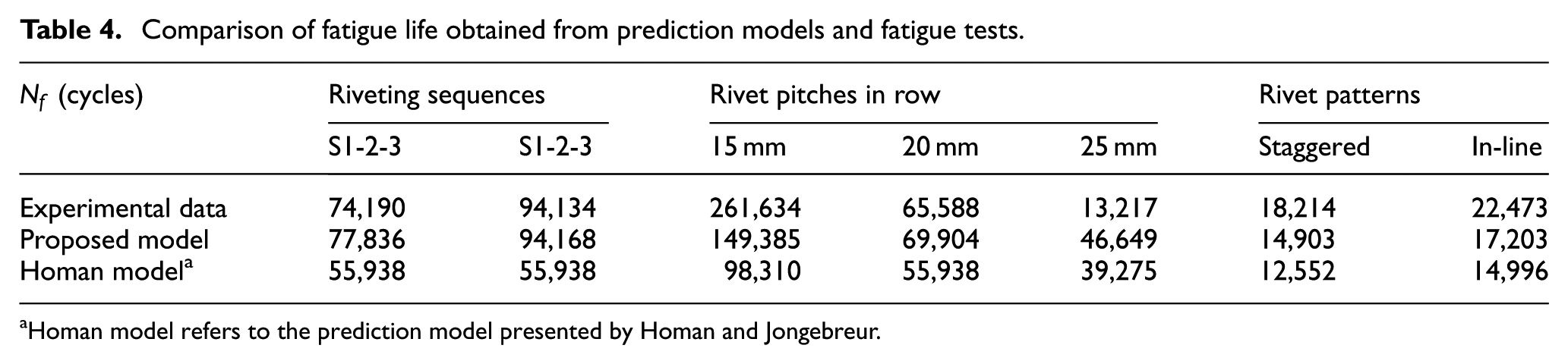
Homan model refers to the prediction model presented by Homan and Jongebreur.
It can be seen from Table 4 that the fatigue life predicted by the Homan and Jongebreur model is evidently conservative because the effect of residual stress on the fatigue life of riveted joints was not considered. In addition, the identical fatigue life is calculated by the Homan and Jongebreur model for specimens with different riveting sequences. The Homan and Jongebreur model is limited in its applicability since this model just depends on the geometry of the riveted specimen.
The predicted results calculated by the new developed model are much closer to the experimental data. The accuracy of the fatigue life prediction is improved by introducing the combining effect of residual stress and remoting tensile loads. The tendency of the fatigue life of various riveting sequences is revealed by the proposed model. The discrepancies of the predicted results mainly appear in the single-row riveted specimens with rivet pitch P = 15 and 25 mm. The larger compressive residual stress in the riveted specimen with P = 15 mm results in the movement of the fracture location from the net cross section, as shown in Figure 13. The equivalent stress amplitude calculated by the proposed model is higher than that of the riveted specimen with rivet pitch P = 15 mm. The failure of the riveted specimen with rivet pitch P = 25 mm is a result of the shear fracture of rivets, which fails to satisfy the assumption of the prediction model that the fatigue crack is located at the edge of the rivet hole. Thus, the apparent discrepancy of the prediction result occurs for the riveted specimen with P = 25 mm.
Conclusion
The combined effect of the residual stress caused by riveting patterns and pitches on the local stresses of the riveted lap joint is numerically studied. The local stresses involve the residual stress induced by the riveting process and the cyclic stress induced by the remote tension. The fatigue tests are conducted to study the fatigue life of riveted specimens with various parameters. The residual stress at the edge of rivet hole is used in the fatigue life prediction to evaluate the effect of riveting patterns and pitches on the riveted joint. The conclusions can be drawn as follows.
The larger compressive residual stress appears in the riveted lap joint with the riveting sequence S1-3-2. This riveting sequence decreases the circumferential stresses under the remote tensile loading, which is recommended for riveted structures.
A smaller rivet pitch yields a higher compressive residual stress at the edge of rivet hole, which is beneficial to the fatigue behavior of the riveted joint. Meanwhile, smaller rivet pitch is favorable for the reduction of the stress concentration.
The region and the magnitude of the compressive residual stress are found to increase in the specimen with the in-line riveting. At the edge of rivet hole, the smaller circumferential stress appears in the triple-row riveted specimen with the in-line riveting.
The fatigue cracking paths of fractured specimens reveal the correlation of the fatigue behaviors of riveted joints and riveting patterns and pitches. The proposed model may predict the fatigue life well by the comparisons of the testing data and numerical results.
Footnotes
Declaration of conflicting interests
The author(s) declared no potential conflicts of interest with respect to the research, authorship, and/or publication of this article.
Funding
The author(s) disclosed receipt of the following financial support for the research, authorship, and/or publication of this article: This study was financially supported by the National Natural Science Foundation of China (51775345) and the State Key Development Program of Basic Research of China (2014CB046600).