
Abstract
This article presents new joining-by-forming processes to assemble longitudinally two metal–polymer sandwich composite panels perpendicular to one another. Process design draws from an earlier development of the authors for metal sheets to new concepts based on the combination of sheet-bulk forming with mortise-and-tenon joints. Selected examples obtained from experimentation and finite element modelling give support to the presentation. A new three-stage joining by the forming process is capable of producing mechanically locked joints with larger and stiffer flat-shaped heads than those fabricated by alternative single- or two-stage solutions. Failure in the new three-stage joining by the forming process is found to take place by cracking instead of disassembling after unbending the flat-shaped head of the joint back to its original shape. The required forming forces to produce the new metal–polymer joints are below 15 kN, allowing them to be an effective, easy-to-implement alternative to existing solutions based on adhesive bonding, welding and mechanical fastening.
Keywords
Introduction
A metal–polymer sandwich composite is a prefabricated material made of three layers consisting of a thick low-density core and two thin metal sheets bonded to each side of the core. These materials are cost effective and versatile in applications where a combination of high structural rigidity, low weight and thermal, noise and/or vibration insulation is required.
In the last years, there has been a growing interest of the automotive industry in the utilization of metal–polymer sandwich composites to make vehicles lighter, safer and more fuel efficient. In the case of steel–polymer sandwich composites that are the focus of this article, potential applications encompass a wide variety of automotive components such as roof, hood, fenders, doors and floor panels. 1 As a result of this, research has been concentrated on forming2,3 and joining processes. 4
However, the use of steel–polymer sandwich composites has been limited due to the costs associated with the materials and processes. With regard to the latter, major problems are related to the need of joining steel–polymer sandwich composites with adjoining components and body-in-white structures.
The rapidly growing interest of metal–polymer sandwich composites for applications in aircrafts, ships and trains 5 has also been limited by the same type of difficulties. Consequently, innovative, less expensive processes for joining sandwich composites need to be developed to make the use of these materials more affordable and widespread.
The existing technologies for joining metal–polymer sandwich composites can be classified into four different groups: adhesive bonding, welding, mechanical fastening and joining by forming (Figure 1).6,7
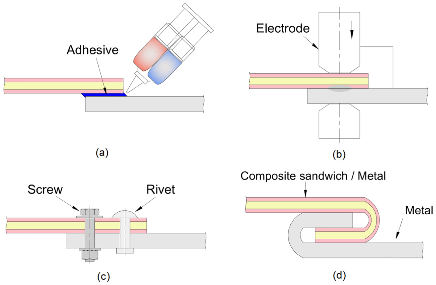
Existing technologies to join metal–polymer composite sandwiches: (a) adhesive bonding, (b) welding-based technologies (e.g. spot welding), (c) mechanical fastening (e.g. screws and nuts) and (d) joining by forming (e.g. hemming/seaming).
Adhesive bonding (Figure 1(a)) is a consolidated joining technology in the automotive industry that requires surface preparation, application and curing of the adhesives at room or elevated temperatures. 8 During the curing time, clamps, jigs and fixtures are used to lock and hold the metal–polymer sandwich composites in position and to ensure a uniform application of pressure. Major drawbacks are surface preparation, long curing times and sensitivity to service temperature, applied stresses and fluids. Disassembling of adhesive bonded joints is difficult.
Welding-based technologies applied to metal–polymer sandwich composites include spot, induction, ultrasonic and laser welding. Spot welding (Figure 1(b)) makes use of dual-pulse power supplies to make a weld. 9 The first pulse employs a shunt tool to heat and squeeze out the non-conductive polymer core in order to obtain a metal–metal contact between the two outer layers. The second pulse forms the weld nugget.
Induction, ultrasonic and laser welding are based on the melting of the polymer core to form a joint with the metals after consolidation. 6 The major drawbacks are thermal degradation of the polymer with possible diminishing of the local strength, long joining times and applicability restricted to overlap joints. Disassembling of welding-based joints is also difficult.
Mechanical fastening (Figure 1(c)) is the dominant technology for joining metal–polymer sandwich composites. The use of screws and rivets is consolidated in the automotive industry 10 and the resulting joints are easily assembled and disassembled without damaging the sandwich composites. Mechanical fastening circumvents most of the drawbacks of adhesive bonding and welding-based technologies but introduces other sort of disadvantages and limitations. The mechanically fastened joints expose the sandwich composites to concentrated stresses, and their performance is dependent on the maximum service load that screws and rivets can safely withstand and are sensitive to creeping under the influence of thermal stresses. In addition, mechanical fastening increases the overall weight of the structures by the use of screws and/or rivets.
Application of joining by forming to metal–polymer sandwich composites is nowadays limited to table-top hemming (machine hemming) and roller hemming (Figure 1(d)). Both processes are state-of-the-art solutions that have been successfully applied to the fabrication of automotive door outer panels. 1 However, their implementation is complex and demands significant investments in equipment purchase and/or modification, which prevents its use in small batch size applications.
Under these circumstances, the main objective of this article is to present and discuss new joining-by-forming processes to assemble longitudinally in position two metal–polymer sandwich composite panels perpendicular to one another. The design of the processes draws from an earlier development of the authors for metal 11 and polymer 12 sheets, to new solutions based on multi-stage sheet-bulk forming 13 sequences that are more appropriate for sandwich composites. The main goal is to obtain mechanically locked joints that are capable of providing good pull-out forces while being able to be produced in conventional tools and machine tools.
The presentation is supported by experimentation and finite element modelling and emphasis is placed on the observed modes of deformation, required forming forces and maximum pull-out forces that the joints are able to withstand before failing.
Experimentation
Stress–strain curves
The development of the new joining-by-forming processes was performed with LITECOR sandwich composite panels supplied by thyssenkrupp. The panels had a thickness
The stress–strain curves of the polymer core and of the steel sheets were determined by means of stack compression tests, which allowed obtaining the stress response of both materials for large values of strain, namely, for those beyond necking in tension 14 (Figure 2). Tension tests were not performed for complete characterization of the strength differential effect of the polymer core because the main acting stresses during joining by forming are compressive.
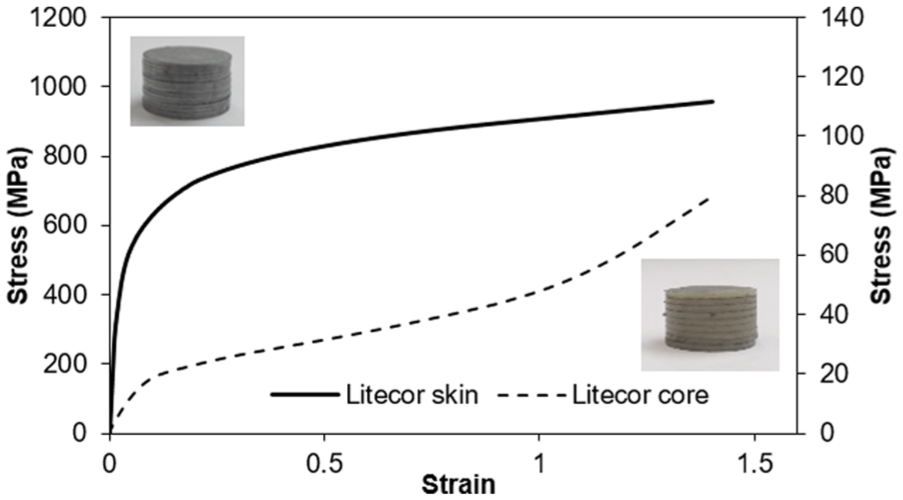
True stress–strain curves of the materials from the two different layers of the LITECOR steel–polymer sandwich composite panels.
The stack compression tests were carried out at room temperature in a hydraulic testing machine with a cross-head speed equal to 10 mm/min and the specimens were assembled by pilling up circular discs cut out from the two different layers of the sandwich composite panels.
New proposed joining-by-forming processes
Three different process designs were investigated (Figure 3). The first design concept was based on the single-stage solution developed by Bragança et al.,11,12 which employs flat punch upsetting of the tenon in the direction perpendicular to thickness for achieving a mechanical lock between the two sandwich composite panels (Figure 3(a)).
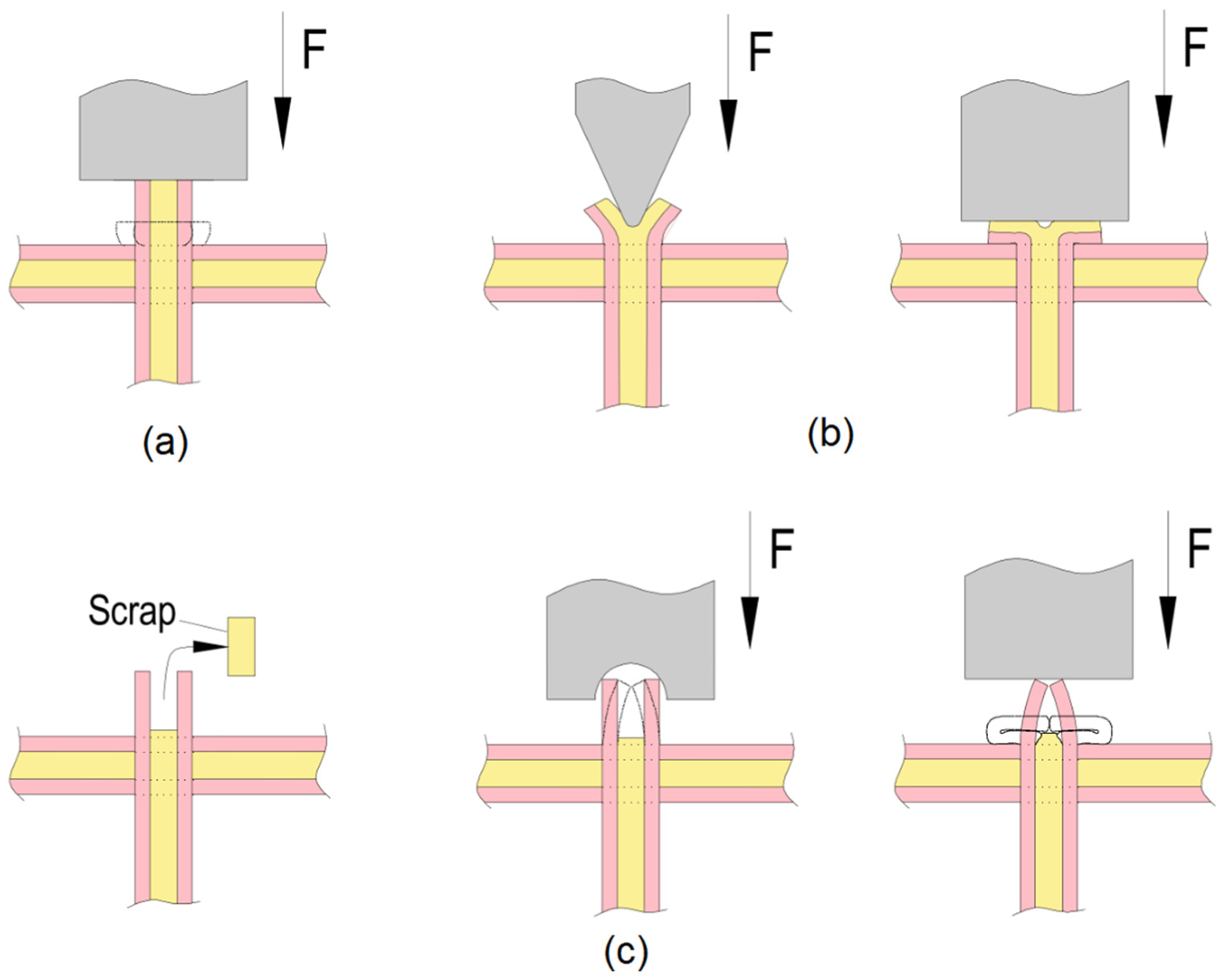
Joining-by-forming processes based on sheet-bulk forming applied to metal–polymer sandwich composite panels: (a) single-stage process developed and applied to metal sheets by Bragança et al.;11,12 (b) two-stage process involving V-shaped indentation and upset compression of the tenon and (c) three-stage process involving cutting, nosing and upset compression of the tenon.
The second design concept is an innovative two-stage joining-by-forming process that combines V-shaped indentation with flat punch upsetting of the tenon in the direction perpendicular to sheet thickness (Figure 3(b)). The main advantage of this process is the capability of increasing the flat-shaped head of the joint without damaging the sandwich composite panels by overpressure.
The third design concept is the innovative three-stage joining-by-forming process shown in Figure 3(c). In the first stage, the polymer core of the tenon placed above the surface of the mortise is removed with a small cutting tool inclined at a rake angle and having a straight cutting edge. The second and third stages perform the nosing and the flat punch upsetting of the outer thin metal sheets of the tenon. The goal is to enlarge the flat-shaped head and simultaneously add a compression bead in order to increase the overall strength of the joint, as will be shown later in this article.
The development of the new joining-by-forming processes was carried out in ‘unit cells’ that replicate the mortise-and-tenon joints utilized for fixing longitudinally in position two sandwich composite panels perpendicular to one another. The ‘unit cell’ concept had already been used by the authors in a previous experimental work on tee joints made from metal and polymer sheets perpendicular to one another11,12 and in lap joints made from metal sheets in which one sheet is partially placed over another. 15
A typical ‘unit cell’ is made of a small sample with a tenon, which is longer than wider, and another small sample with a mortise consisting of a rectangular through-thickness hole (Figure 4). The ‘unit cells’ were cut out from the supplied LITECOR sandwich composite panels by water jet.
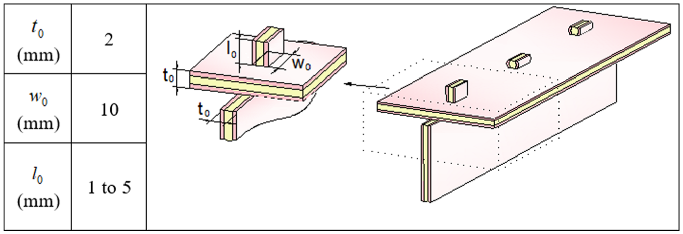
Geometries of the tenons and mortises that were utilized in the experiments.
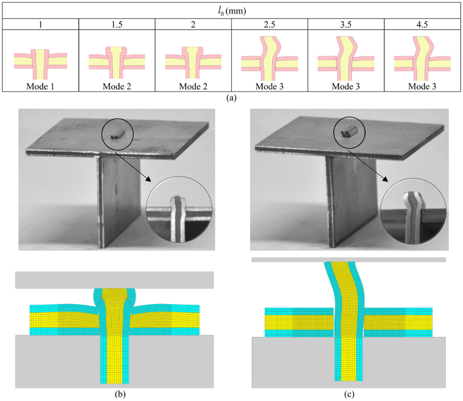
Figure 4 summarizes the geometry and dimensions of the mortises and tenons that were utilized in the experiments. As seen, only the free length
Numerical modelling
Numerical modelling of the joining-by-forming processes was carried out with the in-house finite element computer program I-form. 16 The program is based on the irreducible finite element flow formulation and is being developed by the authors since the end of the 1980s
In the above functional,
Friction is modelled through the utilization of the law of constant friction
In this investigation, the effective stress
The finite element models made use of plane strain deformation conditions and discretized the cross-section of the sandwich composite panels by means of quadrilateral elements (Figure 5). The tools were modelled as rigid objects and their geometries were discretized by means of linear contact friction elements.
Finite element simulation of a joint produced by the three-stage joining-by-forming process that is schematically illustrated in Figure 3(c) at the beginning and end of the (a) second and (b) third stages
A detailed description of the computer implementation of the irreducible finite element flow formulation in I-form with special emphasis on the numerical treatment of the contact with friction between deformable objects and between deformable and rigid objects is given by Nielsen et al. 18
Results and discussion
Single-stage joining-by-forming process
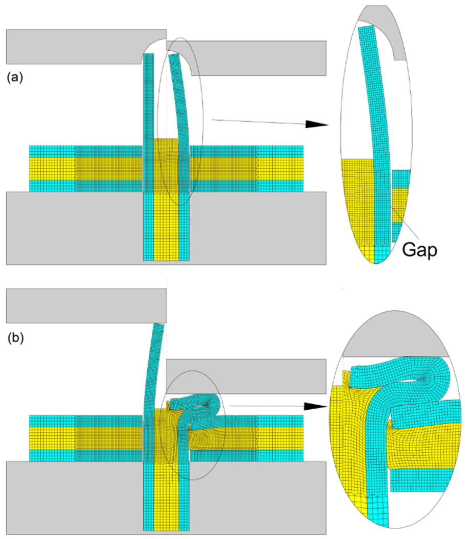
Figure 6(a) presents a summary of the experimental results obtained in single-stage joining by forming of LITECOR sandwich composite panels using different free lengths
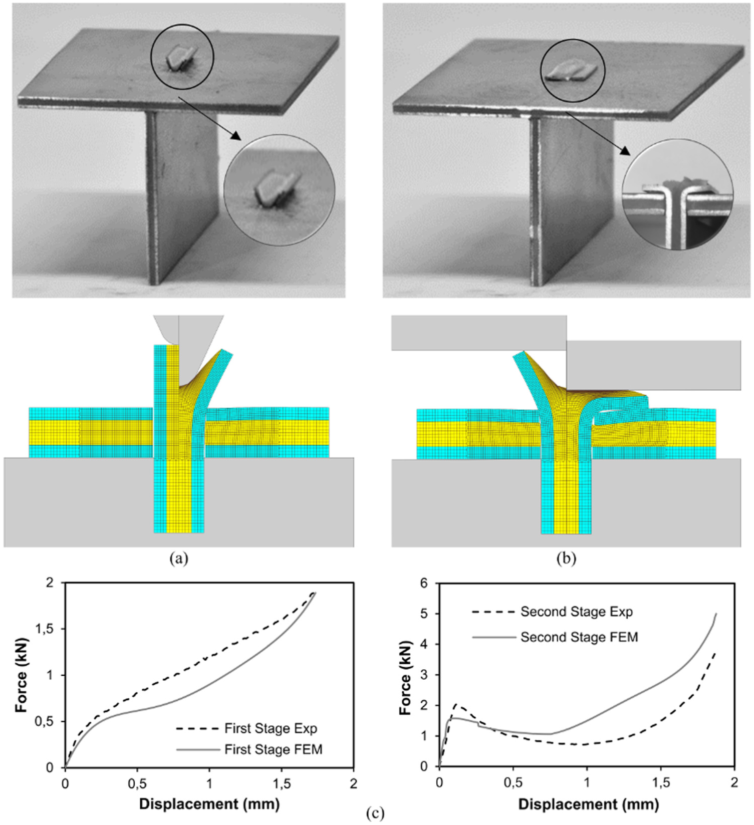
Assembling two LITECOR sandwich composite panels perpendicular to one another by means of single-stage joining by forming: (a) summary of the experimental observations for the entire set of test cases listed in Figure 4; (b) photograph and finite element–predicted cross section of a joint produced under deformation mode 2
The upset compression of very short tenons gives rise to symmetric outward material flow with small surface expansion. This mode of deformation that will be designated as mode 1 is responsible for producing joints with a flat-shaped head that is considered too small to support the tension loads applied along the axis of the tenon. For this reason, the joints produced under deformation mode 1 are classified as inappropriate.
The difference between deformation modes 1 and 2 is related to the size of the flat-shaped head which becomes larger as the free length of the tenon increases. Mode 2 is typical of sound (appropriate) joints having a length of the flat-shaped head larger than 1.5 times the original thickness
Finally, deformation mode 3 is typical of slender tenons (say,
Figure 6(b) and (c) shows the photographic details and the corresponding finite element–predicted geometries of the cross sections of two joints produced under deformation modes 2 and 3. The overall agreement is very good.
A similar good agreement between experimental and numerical results is obtained for the evolution of the upset compression force with displacement (Figure 7). The main differences are related to the type of deformation mode. In the case of mode 2, there is a monotonic growth of the force with displacement as a result of the progressive compression of the flat-shaped head of the tenon against the lower sandwich composite panel containing the mortise.
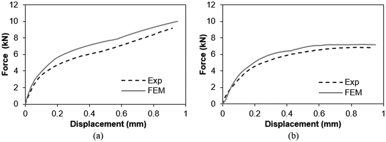
Evolution of the experimental and finite element–predicted upset compression force with displacement for typical joints produced under (a) deformation mode 2
In the case of mode 3, the evolution of the force with displacement deviates from that of mode 2 due to compensation of the increase in force due to strain hardening and surface expansion with the reduction in force caused by asymmetric material flow due to plastic instability (buckling) of the tenon. In fact, after a displacement of approximately 0.5 mm, the force stops growing and reaches a constant value.
Although the results show that single-stage joining by forming, which was originally developed for metal sheets, can be successfully applied to sandwich composite panels, its workability window is limited. Slender tenons with
Two-stage joining-by-forming process
The first approach to increase the flat-shaped head of the joints without damaging the sandwich composite panels by overpressure lead to the design of a two-stage joining-by-forming process that combines V-shaped indentation with flat punch upsetting of the tenon in the direction perpendicular to sheet thickness (Figure 3(b)).
Figure 8 shows the successful application of two-stage joining by forming in the case of a tenon with
Assembling two LITECOR sandwich composite panels perpendicular to one another by means of the new proposed two-stage joining by forming: (a) photograph and finite element–predicted cross section of a joint at the beginning and end of the first stage
In general terms, two-stage joining by forming splits the thickness of the tenon into two parts, bends each part along the V-shaped surface of the indentation punch and upsets each part against the lower sandwich composite panel containing the mortise. The agreements between the experimental and finite element–predicted cross sections (Figure 8(a)) and between the measured and computed force versus displacement evolutions (Figure 8(b)) are good for both stages of the process.
However, two-stage joining by forming is not an effective alternative to the previously developed single-stage solution as it will be better understood in the final section of this article (destructive pull-out tests). In fact, the resulting joints are only capable of withstanding a fraction of the pull-out forces of those produced by single-stage joining by forming.
Three-stage joining-by-forming process
Three-stage joining by forming is the solution to circumvent the problems of plastic instability of single-stage joining by forming applied to sandwich composite panels and to simultaneously increase the flat-shaped head and strength of the mechanically locked joints.
As shown in Figure 9(a), the process is carried out in three different stages comprising cutting out the polymer core of the tenon placed above the surface of the mortise (not shown in the figure) followed by nosing and flat punch upsetting of the outer thin metal sheets of the tenon. The last two stages are utilized to form a compression bead that will increase the pull-out forces due to metal reinforcement of the flat-shaped head of the joint. The overall agreement between the experimentally and numerically predicted cross-sectional geometries is very good.
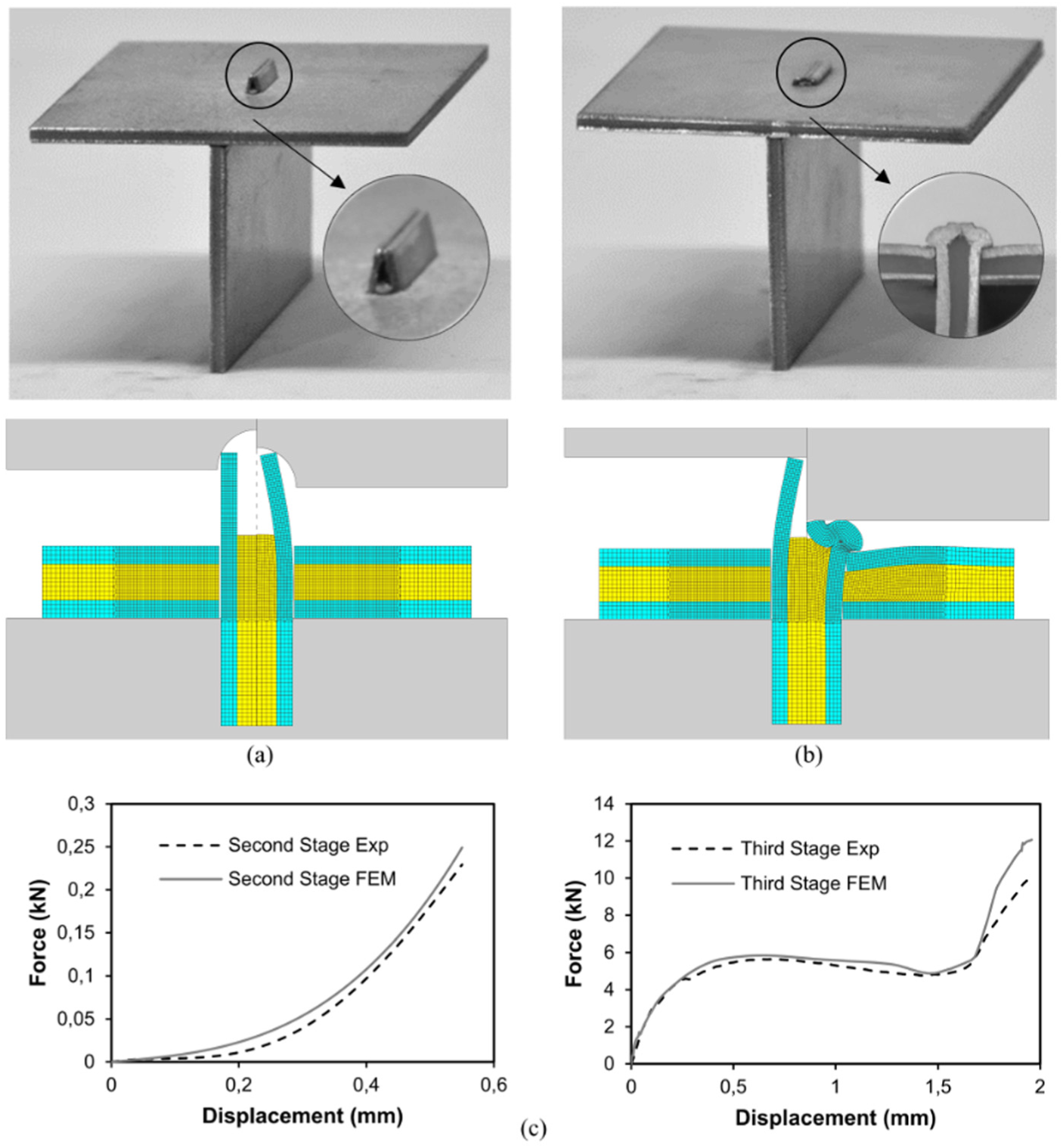
Assembling two LITECOR sandwich composite panels perpendicular to one another by means of the new proposed three-stage joining by forming: (a) photograph and finite element–predicted cross section of a joint at the beginning and end of the second stage
As shown also in the finite element simulation results included in Figure 5, the new proposed process is capable of producing large flat-shaped heads from slender tenons because it takes advantage of plastic instability to produce a compression bead instead of being limited by plastic instability, as in the case of single-stage joining by forming.
The evolution of the force with displacement in Figure 9(b) allows distinguishing between the monotonic growth of nosing and the two-region trend of upset compression, which ends by disclosing a steep increase of the force as the flat-shaped head of the tenon is subjected against the lower sandwich composite panel containing the mortise. In both cases, the force is below 15 kN allowing the process to be easily performed with low-cost equipment.
Destructive pull-out tests
The overall performance of the three different joining-by-forming processes was assessed by means of destructive pull-out tests aimed at determining the maximum force that the joints are able to withstand before failure. The tests were carried out for the entire set of tenons and mortises listed in Figure 4.
The experimental setup is schematically illustrated in Figure 10(a) and the results of the tests are included in Figure 10(b). As seen, the larger pull-out forces are obtained for the joints produced by means of the three-stage joining-by-forming process and the smaller pull-out forces are obtained for those produced by the alternative two-stage joining-by-forming solution.
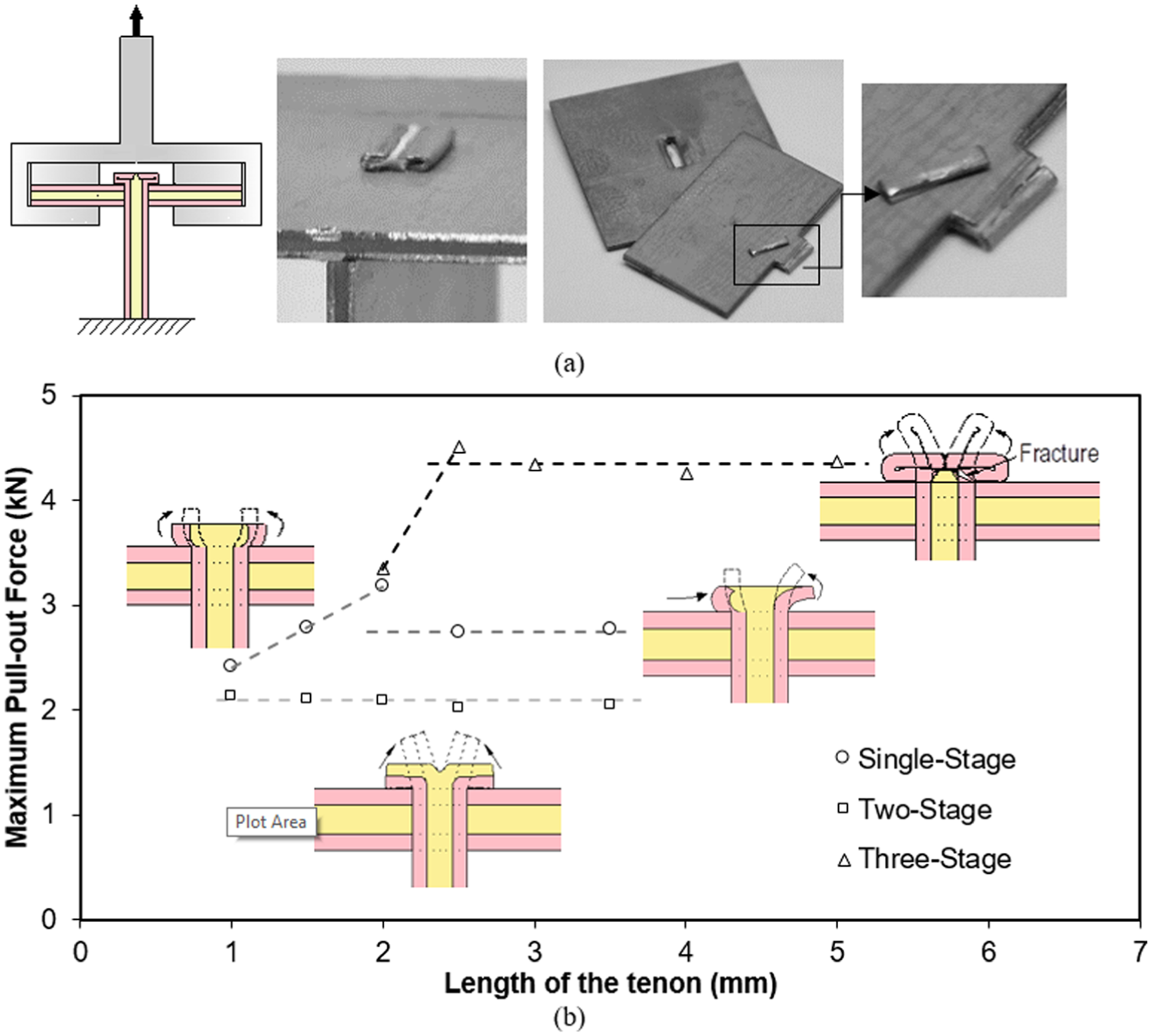
Destructive pull-out tests of the joint produced by the three joining-by-forming processes: (a) schematic representation of the experimental setup with photograph of a joint produced by the three-stage joining-by-forming process before and after testing and (b) maximum pull-out forces as a function of the length
It is also interesting to observe that in the case of the single- and three-stage joining-by-forming processes the pull-out force increases with the length
The above explanation allows understanding the top performance of these joints which fail by cracking (Figure 10(a)) instead of failing by disassembling after unbending the flat-shaped head back to the longitudinal axis of the tenon, as in the case of the joints obtained by means of the two-stage joining-by-forming process (refer to the inset drawing schemes in Figure 10(b)).
Conclusion
This article presents innovative joining-by-forming processes to assemble longitudinally in position two metal–polymer sandwich composite panels perpendicular to one another. An innovative three-stage solution comprising cutting out the polymer core of the tenon placed above the surface of the mortise followed by nosing and flat punch upsetting of the outer thin metal sheets of the tenon is capable of producing mechanically locked joints with larger and stiffer flat-shaped heads than those fabricated by single- or two-stage joining-by-forming processes. The resulting joints can withstand higher pull-out forces of up to 4.5 kN and fail by cracking of the flat-shaped heads instead of being disassembled after unbending the flat-shaped heads back to the longitudinal axis of the tenon, as in the case of the joints produced by alternative joining-by-forming solutions.
Despite being reinforced with metallic compression beads, the joints produced by three-stage joining by forming still need less than 15 kN to be produced. This makes the new proposed process an effective, inexpensive solution for joining sandwich composites with portable equipment and to make the use of these materials more affordable and widespread in industry.
Footnotes
Declaration of conflicting interests
The author(s) declared no potential conflicts of interest with respect to the research, authorship and/or publication of this article.
Funding
The author(s) disclosed receipt of the following financial support for the research, authorship, and/or publication of this article: The authors would like to acknowledge the support of Fundação para a Ciência e a Tecnologia of Portugal under LAETA-UID/EMS/50022/2013 and PDTC/EMS-TEC/0626/2014 and the support provided by thyssenkrupp Steel Europe AG and Dr Azeddine Chergui. The support provided by Instituto Politécnico de Lisboa under IPL/2016/CompSBJ_ISEL is also acknowledged.