
Abstract
It is a great challenge to improve the process stability in conventional underwater wet welding due to the formation of unstable bubble. In this study, mechanical constraint method was employed to interfere the bubble generated by underwater wet welding, and the new method was named as mechanical constraint assisted underwater wet welding. The aim of the study was to quantify the combined effect of wire feed speed and condition of mechanical constraint on the process stability in mechanical constraint assisted underwater wet welding. Experimental results demonstrated that the introduction of mechanical constraint not only suppressed the bubble without floating but also stabilized the arc burning process. The degree of influence of mechanical constraint, which changed with wire feed speed, played an important role during the mechanical constraint assisted underwater wet welding process. For all wire feed speeds, the fluctuations of welding electrical signal were decreased through introduction of mechanical constraint. The difference in the proportion of arc extinction process between underwater wet welding and mechanical constraint assisted underwater wet welding became less with increasing wire feed speed. At wire feed speed lower than 7.5 m/min, the improvement of process stability was very significant by mechanical constraint. However, the further improvement produced limited effect when the wire feed speed was greater than 7.5 m/min. The observation results showed that a better weld appearance was afforded at a large wire feed speed, corresponding to a lower variation coefficient.
Keywords
Introduction
Underwater welding has been widely used in the repair and maintenance of ocean engineering structures.1–3 Compared with the dry hyperbaric welding, the wet welding is especially suited for the manufacturing of geometrically complex constructions because it does not require any auxiliary drainage equipment.4–6 The adverse effect of aqueous environment on the weld properties has been well demonstrated in wet method, in which the welding zone is directly contacted with surrounding water.7–9 Hence, the development trend of underwater wet welding (UWW) is determined by the difficulties posed by the presence of water environment. It is of great significance to reveal the coupled mechanism of water and wet welding process in order to improve the joint quality in UWW.
As a typical wet welding method, underwater flux-cored arc welding has emerged with great potential to be applied in deep water. 10 However, the stable burning of welding arc is extremely difficult to be achieved due to the ambient pressure caused by water. Requirements for improving the arc stability and weld properties are especially strict. 11 Consequently, the modification of the composition of electrode coatings12,13 or welding parameters,14–16 which only requires conventional UWW process, is adopted in most of the previous reports. The water environment is also the source of potential diffusible hydrogen present in deposited metal. To reduce diffusible hydrogen content, a few researches have been carried out by preheating, post-weld heat treatment, and metallurgical methods.17–20 Moreover, the cooling rate in the weld is strongly affected by the surrounding water. Rapid cooling can result in the occurrence of brittle bainite and martensite for welding conventional steels, causing a reduction in the mechanical properties. 21 To solve the shortcoming, works are required to elongate the welding thermal cycle.8,22–24 And it is also found that the mechanical strength of the weld bead is related to the chemical composition and waterproof layer of the covered electrodes.25–27 Heat input management or the development of welding technological conditions are necessary in these researches to improve the mechanical properties.22,28,29
The most important role for water environment contributes to the formation of the bubble around the welding zone, defined as arc bubble. 30 Visual sensing of arc bubble has been reported in order to reveal the physical process of UWW. Literature sources recommend the use of the X-ray transmission method or the dysprosium lamp method as background light source for this purpose. 31 The applicability of X-ray transmission method is limited due to its high penetrability. Furthermore, it shows great advantage for capturing clear images of metal transfer in UWW. 32 The dysprosium lamp method provided that its light blocked by arc bubble can be shown a shadow image on the image screen. Recent researches show that clear images of arc bubble can be visually sensed by this method. 31 It has reached a consensus that the interaction of arc bubble with water significantly affects the dynamic properties of the arc and it is also a key factor in providing opportunity to improve the stability of welding process.24,33 This will be of particular interest in the role arc bubble plays in the ability to control its dynamic nature, in assessing its effect on the arc stability and metal transfer and a further understanding of its interaction mechanisms with wet welding process involved.
The susceptibility of arc bubble to process stability can be reduced by applying modified processes and technological methods. In recent years, the researches have focused on the evolution of arc bubble based on modified processes, the application of which is responsible for welding engineer. It involves the optimization of welding parameters such as arc voltage and welding current to minimize the adverse effect of rising arc bubble34–36 or the introduction of a deep narrow groove of workpiece that binds the bubble to the groove, potentially reducing its dynamic interference through the formation of stable protection atmosphere. 37 The second group of actions attempt to realize the active control of arc bubble from the technological methods point of view. From a few literature reports, it has been noted that local cavity method preventing water from entering the welding zone has a significant influence on the arc bubble control. 38 It shows a higher welding speed and better welding stability compared with conventional wet welding. The degree of process stability, in this respect, is that of the choice of welding conditions and parameters, and the development of local cavity designs.39,40 In the case of wet welding with a flux-cored wire, acoustic-control arc bubble method is proposed by using ultrasound effect to restrain the rising of arc bubble.41,42 This is a relatively stable arc burning process, which indicates that process stability can be improved for welding of high strength steel structures. Although the arc bubble control can be achieved with the application of these methods, there is still room for further improvement in the previous reports. This is primarily concerned with low visibility of arc burning zone and high operation difficulty. Hence, the design of arc bubble control is still an urgent requirement and has the vital practical significance.
The literature analysis result shows that a comprehensive solution has never been developed for the problem of the effective control of arc bubble in wet conditions. In our previous work, mechanical constraint assisted underwater wet welding (MC-UWW) was established to realize the active control of arc bubble. 43 The preliminarily study shows that mechanical constraint method can effectively prevent arc bubble from rising and avoid the probability of excessively unstable arc burning process. In this article, the analysis and improvement of process stability in MC-UWW was systematically studied by varying wire feed speed, which is the distinct parameter of the UWW process. The aim of the study was to quantify the combined effects of wire feed speed and condition of mechanical constraint on the process stability, and to establish a detailed relationship among protective bubble, mechanical constraint, and wire feed speed in order to allow determination of the choice of optimal process used in MC-UWW.
Experimental procedure
Bead-on-plate welding tests were carried out at a water depth of 0.5 m. E40 steel was chosen as base material with the dimension of 200 mm × 100 mm × 8 mm. The filler metal was CHT81Ni2 self-shielded flux-cored wire with 1.2 mm diameter. In conventional UWW, a large volume of the heat-induced bubbles was periodically formed on top of the weld pool. The heat-induced bubble was very unstable and dynamically fluctuated over time. Due to the difference of density between water and bubble, the bubble rose along the vertically upward path, which significantly influenced not only the effective heat input into the welding pool but also the process stability such as arc behavior, metal transfer, and weld pool solidification.21,31,33 Hence, bubble perturbation driven by the water is one of the main factors influencing the process stability in UWW. The method based on arc bubble control is effective for improving process stability.
Figure 1 shows the MC-UWW system. The mechanical constraint system was made up of the brass cylinder and the teflon cylinder that were placed prior to welding. They were connected with each other through threaded connection. The bottom surface of the brass cylinder was used to restrain the bubble from rising. The selection of brass and teflon takes into account the special welding environment. Teflon is an insulator that can insulate the welding torch from brass cylinder so that the latter is not charged. Since the bottom surface of the brass cylinder is very close to the welding zone, the welding spatters are easily attached to its surface. Considering that brass has a good thermal conductivity, these spatters are easily removed even if they are attached to the surface. The brass cylinder was processed with the diameter of 30 mm and the thickness of 10 mm, and teflon cylinder was 24 and 45 mm, as shown in Figure 1(b) and (d). Considering that the bubble diameter is between 15 and 25 mm, the diameter of the brass cylinder should be larger than this range, so it is set to 30 mm. The two cylinders are drilled through a central hole so that the welding gun can pass through the hole and extend to the workpiece, where the welding wire and the workpiece ignite an arc for welding. 44 Then the mechanical constraint system is screwed to the welding torch. The angle between workpiece surface and the axis of assembly device is kept at 90°, in order to achieve the better constraint effect in MC-UWW process.
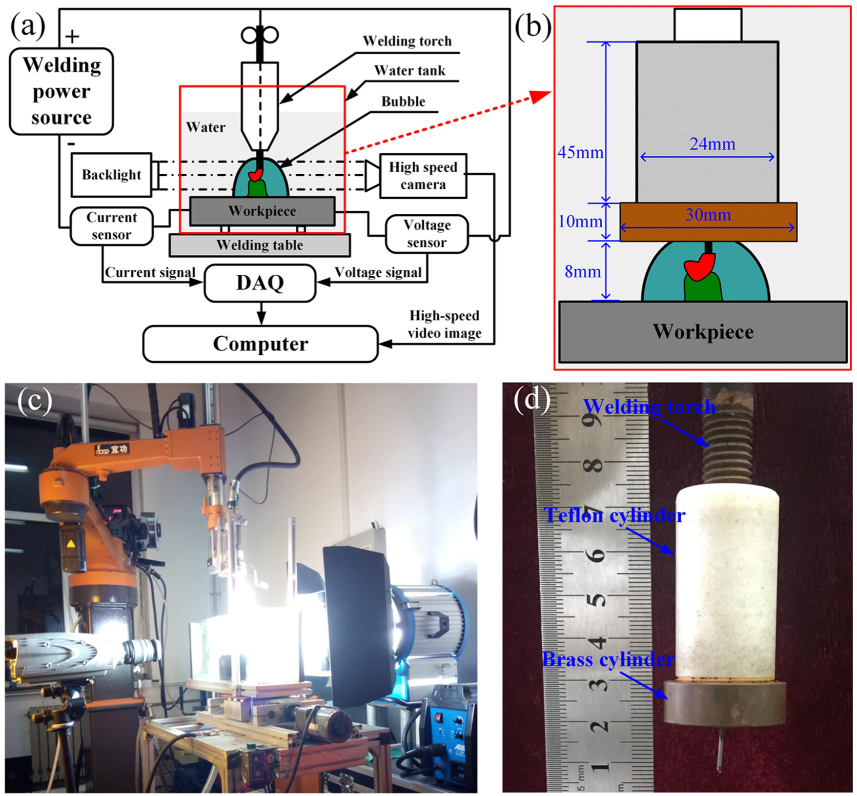
Mechanical constraint assisted UWW system: (a) schematic view of measurement system, (b) schematic view of proposed method, (c) experimental setup, and (d) photograph of mechanical constraint system.
The addition of mechanical constraint can suppress the unstable bubble and change the bubble shape and its dynamics. Bubble is not floating from the arc burning zone but from the lateral side of mechanical constraint device. It is possible to stabilize the bubble and enlarge its volume for providing a better protective atmosphere, compared with the case using in conventional UWW. As a result, the negative effects related to the unstable heat-induced bubble can be reduced or even eliminated by applying the effective control of the bubble under the action of mechanical constraint.
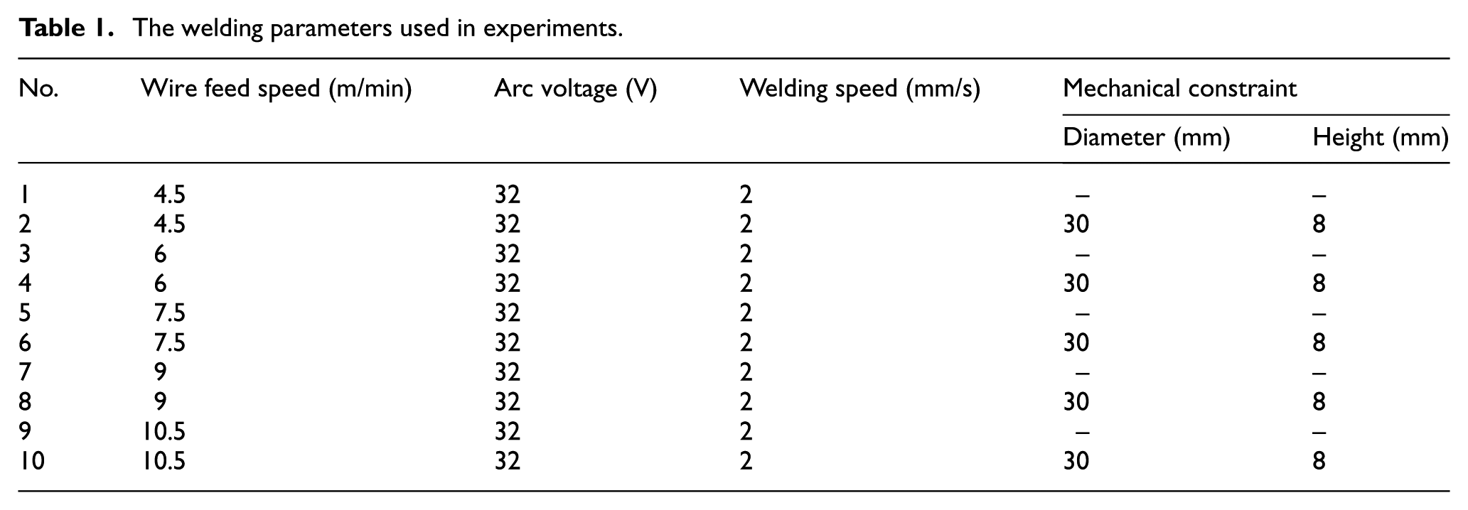
To identify the common set of optimized process parameters, MC-UWW process was conducted at the heights between the workpiece surface and the lower surface of brass cylinder in the range of 8 to 20 mm. By analyzing the bubble dynamics and process stability, the optimized process parameter was found to be the height of 8 mm. 44 The above parameter was used throughout the whole study. Furthermore, the effects of wire feed speed with and without mechanical constraint on process stability and weld morphology were investigated systematically. Five different wire feed speeds, 4.5, 6, 7.5, 9, and 10.5 m/min, were used, and two kinds of welding processes, whether mechanical constraint was exerted or not, were realized; 10 experiments were carried out in the study. The wire extension was 16 mm for all experimental cases. Table 1 shows the other welding parameters used in the article. Lincoln Electric® Power Wave® S350 was chosen as the welding power source with a constant-voltage mode used for welding. Direct current electrode positive condition was used during the welding process. Prior to welding, E40 steel plates were cleaned with steel brush and then with acetone to remove any contamination. After welding, metallographic specimens were prepared by linear cutting, polishing, and etching with Nital 4%. Finally, the weld cross-section geometries were measured and summarized.
The welding parameters used in experiments.
As shown in Figure 1(a) and (c), high-speed image unit was used to capture the bubble dynamics. It was composed of the high-speed camera (Olympus I-SPEED 3) and the dysprosium lamp. The sampling frequency was 2000 Hz in the study. The high-speed camera was placed on one side of welding torch and monitored the bubble evolution process. The dysprosium lamp was placed on the other side of welding torch and provided a background light source. When background light was irradiated to the welding area, the wire and the bubble blocked the light source so that the light could not reach the camera, forming a shadow image in the position where the wire and the bubble existed, whereas the background light irradiated to the water could easily reach the camera. Thus, a contrast image of the bubble could be visually viewed on the computer screen. Welding electrical signal acquisition unit was performed by using Hall sensor and a data acquisition card. Hall sensor with a sampling frequency of 100 kHz could capture the welding current and arc voltage signals, which were then transmitted into the data acquisition card. After processing, welding electrial signals could be recorded on a computer. For all welding experiments, the welding torch, high-speed camera, and dysprosium lamp were kept stationary, and the water tank and workpiece moved at a fixed speed.
Results
Figure 2 shows the effect of wire feed speed on the variation coefficients of welding current and arc voltage in UWW and MC-UWW. It can be seen that the variation coefficients of voltage and current for the two processes both gradually decrease with increasing wire feed speed. The decrement rate of the variation coefficients is very significant as the wire feed speed increases from 4.5 to 7.5 m/min, whereas it remains more or less constant with the wire feed speed larger than 7.5 m/min. This phenomenon is more pronounced when operating in UWW. For example, when the wire feed speed is 4.5 m/min, the variation coefficient of welding current is about 0.56 and 0.82 for MC-UWW and UWW, respectively, and the exertion of mechanical constraint makes it decrease by 32%. When the wire feed speed is 10.5 m/min, the variation coefficient of welding current is about 0.16 and 0.17 for MC-UWW and UWW, respectively, and the exertion of mechanical constraint makes it decrease by 6%. Especially, at the range of 4.5 to 7.5 m/min, the exertion of mechanical constraint can result in 27% to 32% reduction in the variation coefficient of welding current under the same welding conditions. However, it only causes 6% to 11% reduction at wire feed speeds of 9.0 and 10.5 m/min. In fact, the process stability is inversely proportional to the variation coefficient. 45 It indicates that the fluctuations of welding current and arc voltage are more severe in UWW, and the process stability gradually deteriorates with decreasing wire feed speed. In addition, for the two processes under the same welding conditions, the variation coefficient of arc voltage is much smaller than that of welding current because the constant-voltage mode from welding power is used in this process.
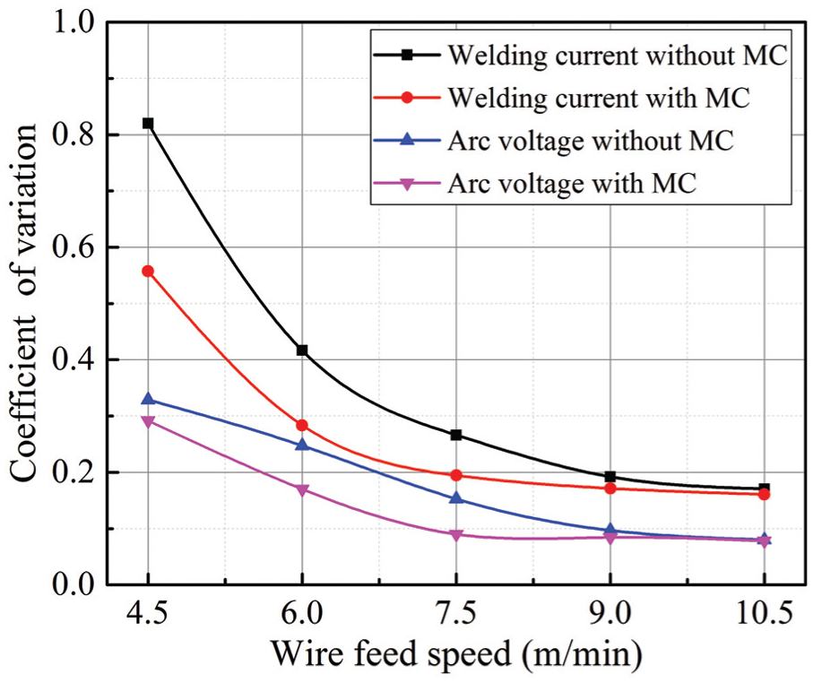
Dependence of variation coefficients of voltage and current on wire feed speed in UWW and MC-UWW.
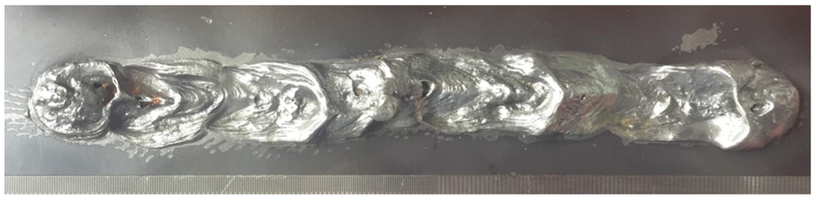
In UWW, the joint quality is closely related to the stability of the welding process. Generally speaking, the more stable the welding process is, the higher the joint quality is. This can be verified by comparing the variation coefficients with weld morphology. Figure 3 shows the weld appearances for different wire feed speeds in UWW and MC-UWW. It can be seen that when wire feed speed is smaller, narrow weld morphology can be observed and there exist some weld pits or spatters in UWW. With the increase of wire feed speed, the weld morphology continues to become wider. Also, weld surface defect can be reduced, indicating the improved joint quality with increasing wire feed speed. This is consistent with the analysis results in Figure 2. It is also noted that when operating in UWW, some weld defects such as weld pits can be still seen and cannot be completely eliminated with wire feed speed increasing to 10.5 m/min, though the variation coefficients are relatively small. This is attributed to the unique characteristics of UWW, leading to unstable arc burning process caused by water environment. According to this perspective, simply modifying welding parameters cannot sufficiently reduce or even eliminate weld defects posed by UWW. When mechanical constraint is applied in UWW, the weld morphology is obviously improved whether using a large or a small wire feed speed. And the arc energy can be better coupled into the welded material resulting in the formation of an excellent weld. Due to the different wire feed speeds, the influence degree of mechanical constraint on weld morphology shows a significant difference. For example, when using a small wire feed speed, the weld appearance can become smooth and broaden in MC-UWW. When using a large wire feed speed, very few weld defects, such as the pits of the weld, are observed compared to UWW. Hence, when operating in MC-UWW, a better weld appearance can be afforded at a large wire feed speed, corresponding to a lower variation coefficient.
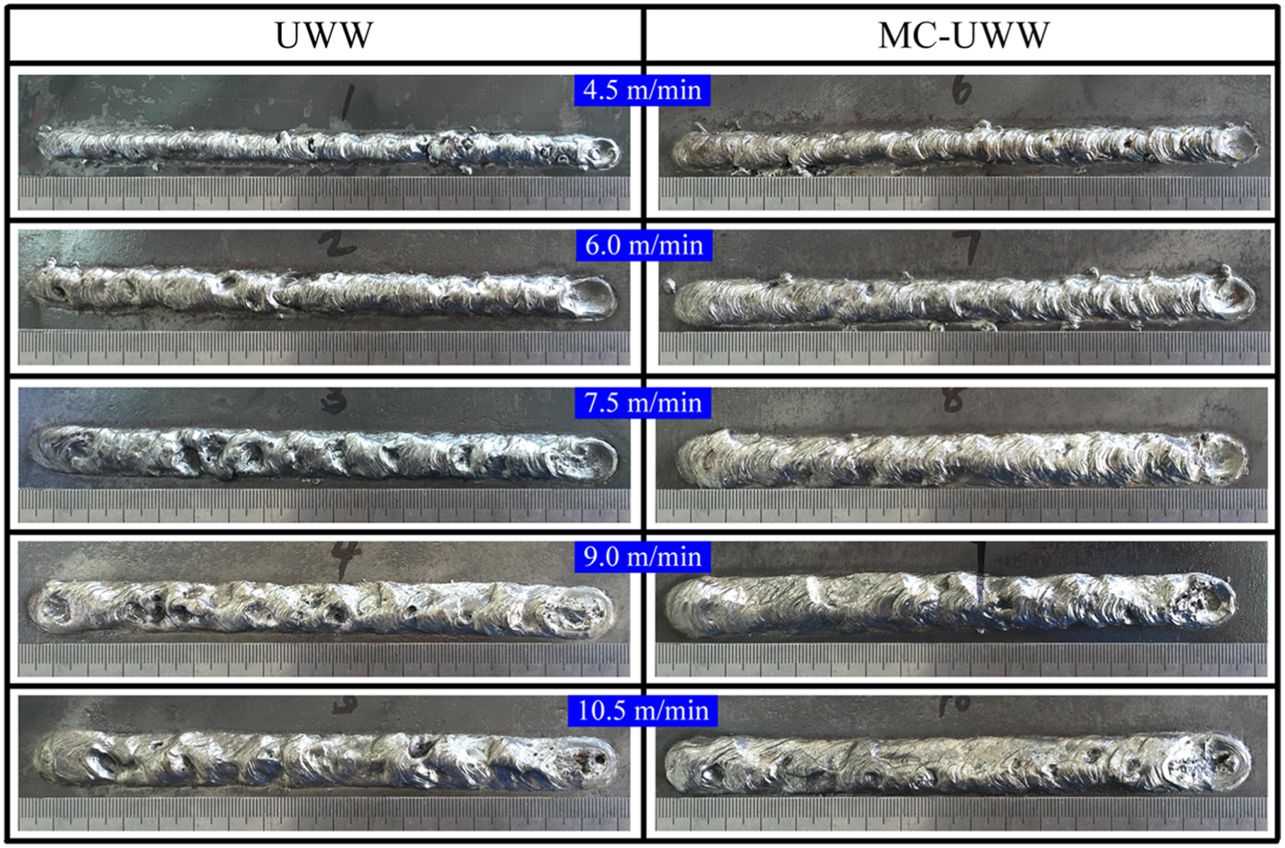
Weld appearances for different wire feed speeds in UWW and MC-UWW.
Discussion
The experimental results indicate that the joint quality is clearly affected by the wire feed speed in both MC-UWW and UWW. This phenomenon can be explained by the relationship among the protective bubble, mechanical constraint, and wire feed speed.
Effect of protective bubble
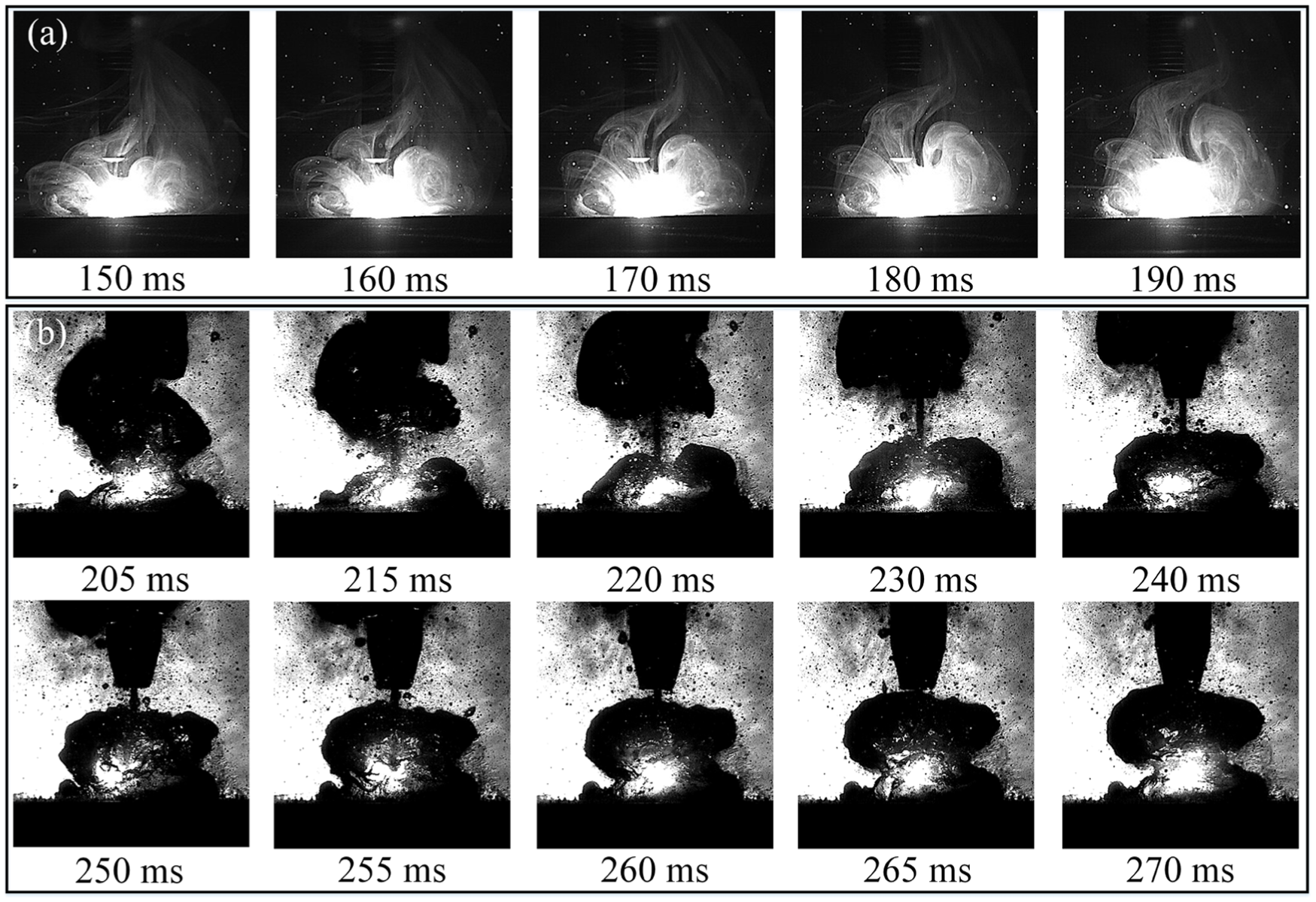
To study the effect of different welding environments on arc behavior, onshore welding and conventional UWW were carried out under the same welding parameters. In addition, no extra shielding gas was provided in the two processes. Figure 4(a) shows the arc behavior in onshore welding. Video S1 provides a direct observation of the arc behavior with time. It can be seen that under the self-shielding gas conditions, a stable welding arc is consistently formed that provides a channel to resist external interference. Under this welding condition, the welding process is very stable, as shown in Figure 5(a), and no liquid metal is ejected from the weld pool forming a spatter. However, when the welding condition is switched from onshore welding to UWW, the protective atmosphere of the welding arc produces a significant difference. As shown in Figure 4(b), the atmosphere surrounding the arc is a dynamic bubble rather than an air environment. The bubble rising along the vertically upward path will absorb a portion of the arc energy and have several adverse effects on the welding process.
Arc characteristics: (a) arc behavior in onshore welding and (b) dynamic behavior of the bubble in UWW.
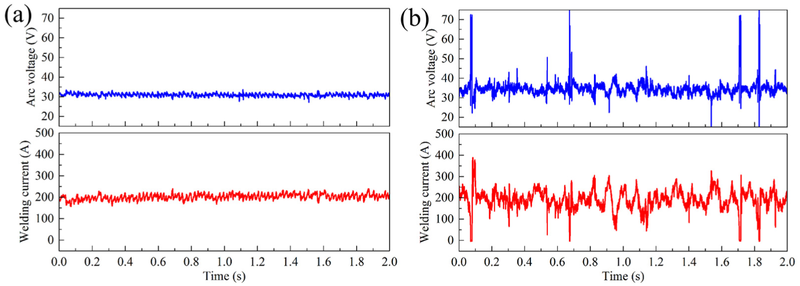
Dynamic characteristics of arc voltage and welding current in (a) onshore welding and (b) UWW.
The large difference in arc behavior between the shielding conditions is a result of the difference in the ambient pressure of air and bubble. Because of the water, bubble has higher ambient pressure and less stability than air. When conducted in onshore welding, the size and morphology of welding arc is stable, and the arc energy can be better transferred to the welded material. However, when the UWW is performed and no extra shielding gas is utilized, a large volume of the heat-induced bubbles will be periodically formed on top of the weld pool, as shown in Figure 4(b). Video S2 provides a direct observation of the bubble behavior in UWW with time. From Figure 4(b), the heat-induced bubble is very unstable and dynamically fluctuated over time. The unstable heat-induced bubble not only significantly influences the coupling efficiency of arc energy into the weld pool but also changes the direction and size of the molten droplet.31,33 Under this welding condition, the bubble tends to oscillate, and the arc behavior, metal transfer, and weld pool solidification will be trapped into the easily ruptured bubble. As shown in Figure 5(b), the waveforms of welding current and arc voltage present considerable fluctuations in UWW because the unstable bubble often adversely affects the arc behavior. This fact suggests that it is critical to control the formation and stability of the heat-induced bubble in order to produce a stable process for UWW, thus achieving sound weld joints.
Effect of mechanical constraint
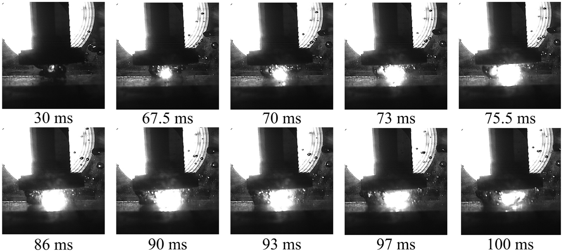
As mentioned previously, the unstable bubble is one of the reasons for the deterioration of process stability.8,31 Furthermore, the negative effects related to the unstable heat-induced bubble can be reduced or even eliminated by applying the effective control of the bubble.40–42 In order to suppress the unstable bubble and then achieve the stable welding process, mechanical constraint was applied in UWW. Figure 6 shows the dynamic behavior of the bubble sampled in MC-UWW. Video S3 provides a direct observation of the bubble behavior in MC-UWW with time. Neither oscillation nor breakup of the bubble is present in the arc burning zone, and a good structural integrity of the bubble is achieved after steady bubble evolution process is established at 75.5 ms. This fact indicates that the MC-UWW process is stabilized by the introduction of mechanical constraint. During MC-UWW process, the mechanical constraint will restrict the bubble in the arc burning zone without floating. Furthermore, the bubble without floating by the use of mechanical constraint can stabilize the turbulent welding arc and metal transfer caused by the gas flow drag force, resulting in the reduced fluctuations of welding current and arc voltage, which will be discussed in Figure 7 by welding electrical signal. Compared with UWW, the perturbation of the bubble is decreased, and the bubble shape and its dynamics are relatively uniform enabling it to be better decoupled with the arc behavior, metal transfer, and generate a stable welding process. Similar to onshore welding, the stable bubble atmosphere surrounding the arc mitigates the impact of high ambient pressure caused by water.
Dynamic behavior of the bubble sampled in MC-UWW.
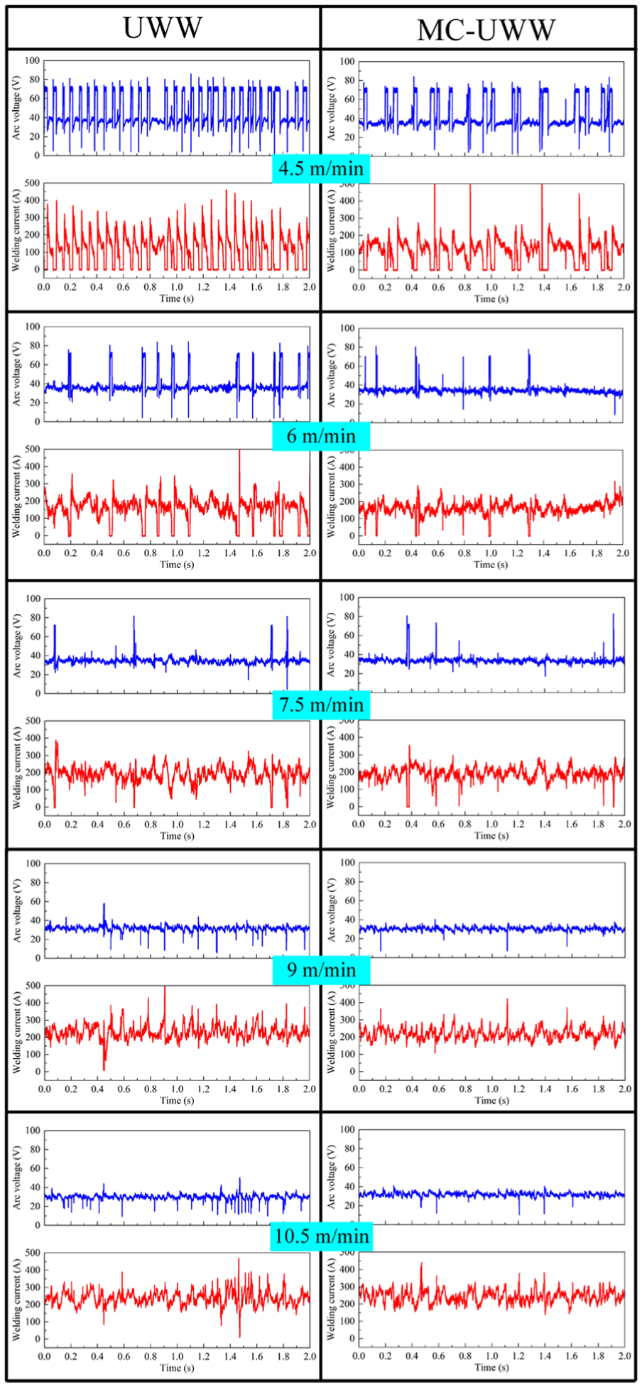
Oscillograms of arc voltage and welding current with varying wire feed speed in UWW and MC-UWW.
In order to study the influence degree of the mechanical constraint on process stability, 10 trial tests were conducted in UWW and MC-UWW, where the wire feed speed was varied from 4.5 to 10.5 m/min in increments of 1.5 m/min. Figure 7 shows the oscillograms of arc voltage and welding current with varying wire feed speed in UWW and MC-UWW. As discussed previously, the introduction of a mechanical constraint into UWW can suppress the unstable bubble and stabilize the welding process. During MC-UWW process, the mechanical constraint plays these possible roles with varying wire feed speed as follows:
For all wire feed speeds, the fluctuations of welding electrical signal are decreased through introduction of mechanical constraint in comparison with UWW. This indicates that the gas flow drag force exerting on molten droplet, caused by the unstable bubble, can be reduced, which makes the oscillation of the droplet weakened. Hence, the potential for formation of weld pits and spatters is further reduced.
At wire feed speeds of 4.5 and 6.0 m/min in UWW, large amount of high transient voltage signals can be generated in the entire recorded time, indicating the worse stability of welding process. This phenomenon has been alleviated when applying mechanical constraint.
In general, the fluctuations of electrical signal tend to be at small amplitudes for the larger wire feed speed than 7.5 m/min. When the wire feed speed is smaller than 7.5 m/min, a large amplitude of fluctuations of electrical signal can be observed in UWW. By introduction of mechanical constraint, the decrement of fluctuation amplitude changes with wire feed speed. The proportion of unstable arc burning process was calculated by dividing the data of greater than 50 V and less than 15 V in a set of data. It was used to quantitatively evaluate the degree of fluctuation amplitude. As shown in Figure 8, when wire feed speed is smaller than 7.5 m/min, the addition of mechanical constraint can result in 6% to 9% reduction in the proportion of unstable arc burning process under the same welding conditions. However, it only decreases by ∼1% at wire feed speed larger than 7.5 m/min.
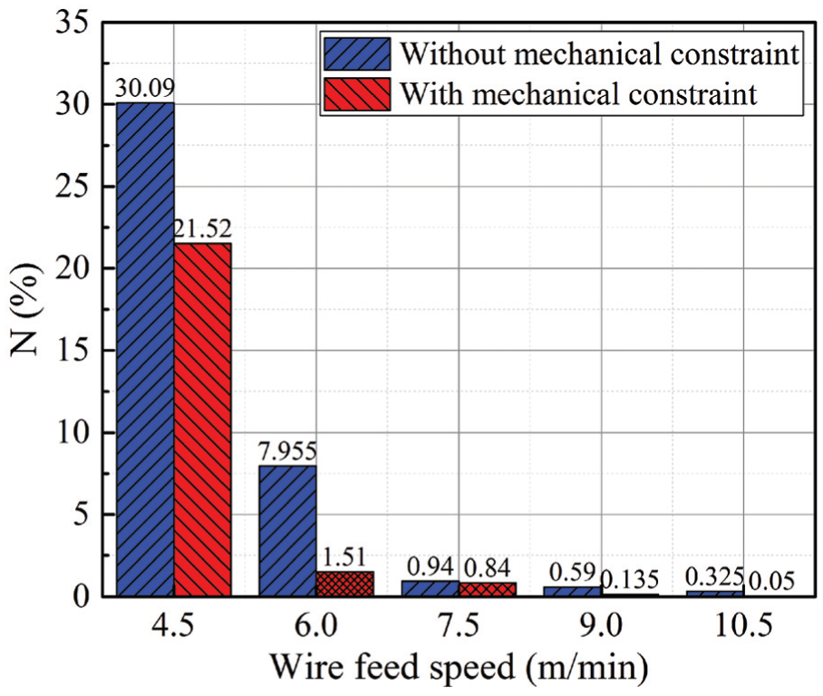
The proportion of unstable arc burning process with varying wire feed speed in UWW and MC-UWW.
Hence, bubble perturbation driven by water is one of the main factors influencing the process stability in UWW. It has been revealed that the addition of mechanical constraint can change the bubble shape and its dynamics. Bubble is not floating from the arc burning zone but from the lateral side of mechanical constraint device, as shown in Figure 6. Meanwhile, the fluctuation amplitude of welding electrical signal can be lowered regardless of wire feed speed. From the above, when mechanical constraint is introduced into conventional UWW, it is possible to stabilize the bubble and enlarge its volume for providing a better protective atmosphere, compared with the case using in conventional UWW.
Effect of wire feed speed
In order to determine whether the optimal welding parameters could be coupled with mechanical constraint, the effect of wire feed speed on arc burning process was further tested in UWW and MC-UWW. The wire feed speed varying from 4.5 to 10.5 m/min in increments of 1.5 m/min was used in the experiments. The arc voltage was set a constant of 32 V. Figure 9 shows the average values of welding current and arc voltage with wire feed speed in UWW and MC-UWW. It can be seen that for the two processes, average values of welding current both gradually increase while average values of arc voltage decrease as the wire feed speed increases. The increase of welding current is because it is directly proportional to the wire feed speed. The decrease of arc voltage with wire feed speed is due to the fact that large amount of high transient voltage signals occurs at the small wire feed speed, as shown in Figure 7. Contrarily, the fluctuation presents a reducing tendency due to the decrease in high transient voltage signals with increasing wire feed speed. Thus, the average value of arc voltage decreases with wire feed speed. Compared with MC-UWW, it can be found that the average value of welding current is relatively large in UWW. This phenomenon is more obvious when wire feed speed is more than 7.5 m/min, whereas at wire feed speed smaller than 7.5 m/min for the average value of welding current, the difference between the two processes has not changed much. Furthermore, the average value of arc voltage in MC-UWW is much smaller than in UWW, the maximum difference of which appears at 4.5 m/min. This is also because the control of arc bubble by mechanical constraint is achieved, resulting in the formation of reduced fluctuations of welding electrical signal.
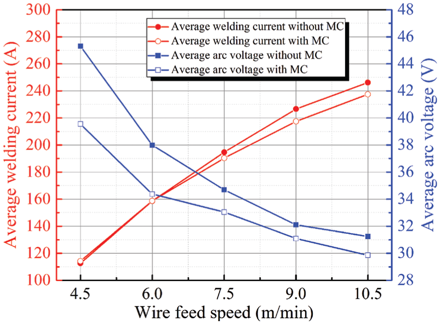
The effects of wire feed speed on the average values of welding current and arc voltage in UWW and MC-UWW.
Figure 10 shows the arc voltage and welding current cyclograms with varying wire feed speed in UWW and MC-UWW. It can be found that three zones are easily seen in every cyclogram. This indicates three processes existing in the entire welding cycle, that is, arc extinction process, short circuiting process, and normal arc burning process. During the welding process, a certain degree of arc extinction process appears in all test cases. However, few signs of short circuiting process can be observed with varying wire feed speed except for the case at larger wire feed speeds of 9 and 10.5 m/min. The difference in the magnitude of short circuiting process is due to the varying wire feed speed used in welding. In addition, the cluster degree of the working point in normal arc burning process significantly strengthen with increasing wire feed speed in both UWW and MC-UWW, that is, the zone of normal arc burning process becomes more dispersive at small wire feed speed, showing a poor process stability. Moreover, with the increase of wire feed speed, the zones of arc extinction process gradually decrease in both UWW and MC-UWW. This phenomenon is more obvious in MC-UWW.
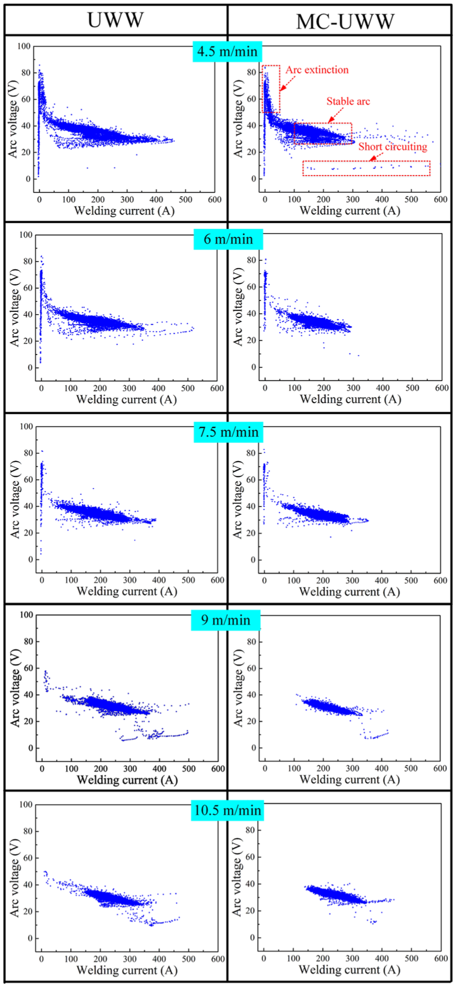
Arc voltage and welding current cyclograms with varying wire feed speed in UWW and MC-UWW.
To accurately evaluate the stability of arc burning process in the entire welding cycle, a further analysis on the proportion of arc extinction process was carried out by setting the voltage threshold of 50 V, as shown in Figure 11. It can be seen that in both UWW and MC-UWW, the proportions of arc extinction process gradually decrease with increasing wire feed speed when it is less than 7.5 m/min. Then as the wire feed speed increases from 7.5 to 10.5 m/min, the proportions almost maintain a constant trend, closing to zero. It is worth noting that the variation in arc extinction process is more dramatic in UWW. For the proportion of arc extinction process, the difference between UWW and MC-UWW becomes less with increasing wire feed speed. Specially, there both exist minimum value of nearly zero at wire feed speed larger than 7.5 m/min for UWW and MC-UWW, showing the superior arc burning process. The reported results confirm the general opinion that the wire feed speed directly affects the arc burning process in MC-UWW, consistent with previous results shown in the “Results” section. The range of possible wire feed speed change is limited by the necessity of providing stability of the arc burning process and achieving sound welded joints. Using the mechanical constraint introduced in this study, a stable welding process will be obtained if the wire feed speed is recommended to be larger than 7.5 m/min in order to ensure the optimal welding parameters.
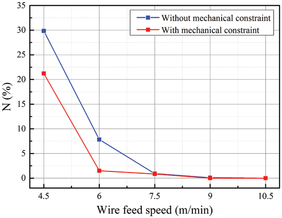
The proportion of arc extinction process with varying wire feed speed in UWW and MC-UWW.
Although the process stability can be significantly improved in MC-UWW by increasing wire feed speed, simply enhancing wire feed speed can lead to the increase in welding heat input. When the wire feed speed is increased to a sufficiently high level of 12 m/min, the overheated weld pool enables the formation of uneven weld for given arc voltage and welding speed. As shown in Figure 12, the severe surface depression of weld is examined under the condition of higher heat input. Hence, the requirement for wire feed speed control should be especially strict. And the contradiction of the heat input in MC-UWW cannot be effectively solved based on the above discussion. In general, high welding heat input may lead to the deterioration of weld appearance and mechanical properties while low heat input may cause poor process stability. Coupled with the mechanical constraint mentioned above, sound joint with excellent weld appearance and acceptable mechanical properties is difficult to be obtained by excessively increasing heat input. Further studies on the influences of heat input on the combination between the process stability and joint quality are needed to be completed for a mechanical constraint condition. In this article, we will not discuss these issues. Therefore, based on the above research results, the wire feed speed is controlled to be 7.5 to 9 m/min in order to obtain excellent weld appearance and possibly acceptable mechanical properties when conducting MC-UWW process.
Weld appearances when applying large wire feed speed of 12 m/min.
Figure 13 shows the cross-sectional macrograph of weld specimens with varying wire feed speed in UWW and MC-UWW, and the corresponding weld penetration, weld width, and weld reinforcement were measured and plotted in Figure 14. All the welds present good cross-sectional macrograph. It can be seen that for the two processes, the weld width, weld penetration, and weld reinforcement approximately increase with increasing wire feed speed. This can be attributed to the variation in heat input caused by wire feed speed. Furthermore, the bubble rising along the vertically upward path can take away a portion of the arc energy, resulting in the reduction in effective heat input. The coupling efficiency of arc energy into the welded material is enhanced by the bubble control through introduction of mechanical constraint. Therefore, smaller weld reinforcement and larger weld width are almost attained in MC-UWW no matter which wire feed speed is used. When wire feed speed appears in the range of 4.5 to 7.5 m/min, deeper weld penetration is attained in MC-UWW, whereas the penetration profile changes from finger-shaped to bowl-shaped at 9.0 and 10.5 m/min.
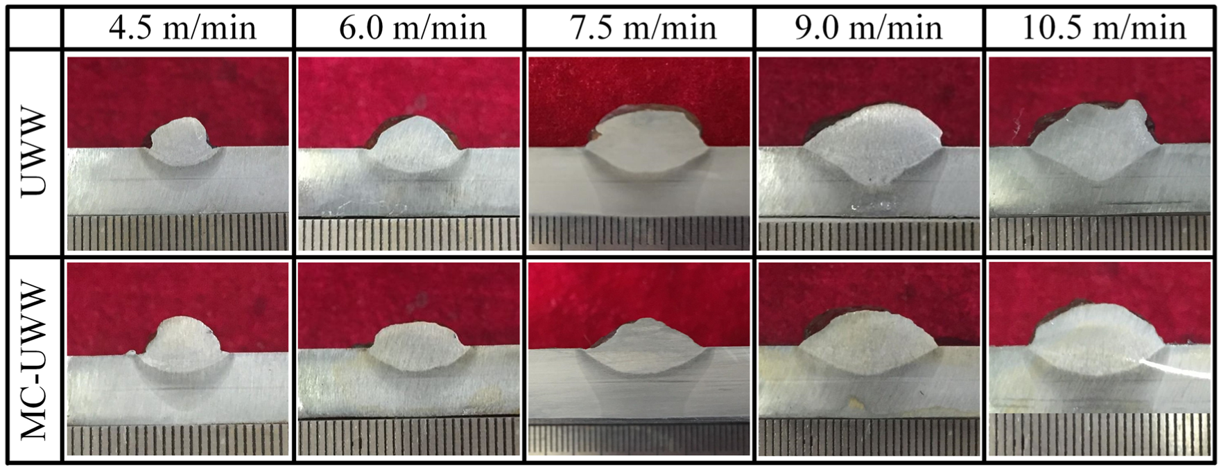
Cross-sectional macrograph of weld specimens with varying wire feed speed in UWW and MC-UWW.
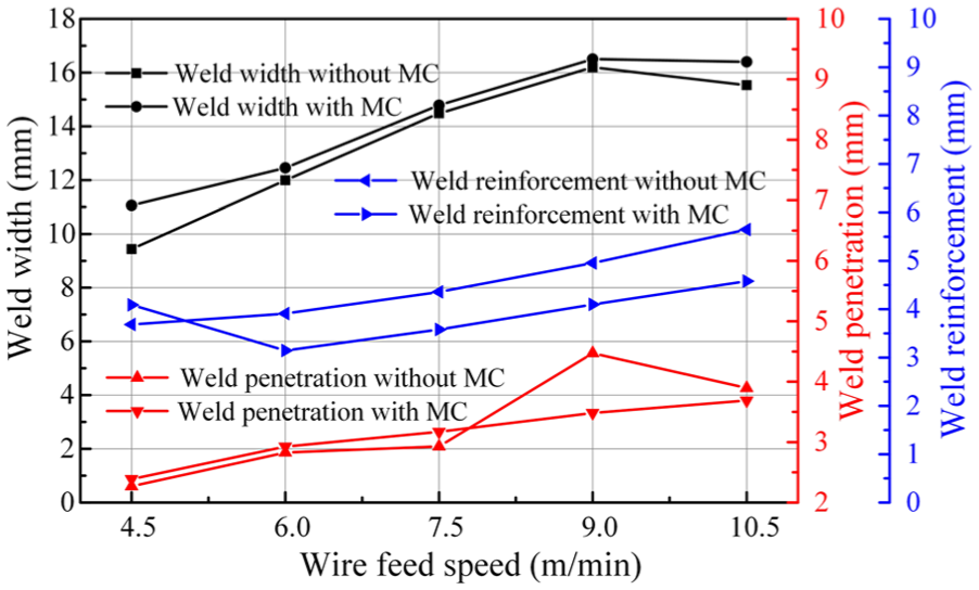
Weld penetration, weld width, and weld reinforcement with varying wire feed speed in UWW and MC-UWW.
From the above, we can effectively improve the process stability by mechanical constraint with varying wire feed speed. The degree of influence of mechanical constraint, which changes with wire feed speed, plays an important role during MC-UWW process. At wire feed speed lower than 7.5 m/min, the improvement of process stability is very significant by mechanical constraint. It is also demonstrated that the further improvement produces limited effect when wire feed speed is greater than 7.5 m/min because wire feed speed deduced process stability is already large enough. For the welding conditions used in this study, a suitable wire feed speed range of 7.5 to 9 m/min can be determined in order to achieve a better process stability in MC-UWW.
Conclusion
The combined effects of mechanical constraint and varying wire feed speed on UWW process were systematically studied. The following conclusions may be drawn:
The variation coefficients of voltage and current in UWW and MC-UWW both gradually decrease with increasing wire feed speed. The decrement rate of variation coefficient is very significant as wire feed speed increases from 4.5 to 7.5 m/min, whereas it almost remains constant with the wire feed speed larger than 7.5 m/min.
Due to the existence of water, bubble has higher ambient pressure and less stability than air. When conducting UWW process, a large volume of the heat-induced bubbles is periodically formed on top of the weld pool, which is very unstable and dynamically fluctuated over time.
During the MC-UWW process, the perturbation of the bubble is decreased, and the bubble shape and its dynamics are relatively uniform enabling it to be better decoupled with the arc behavior and generate a stable welding process.
By introduction of mechanical constraint, the decrement of fluctuation amplitude changes with wire feed speed. When wire feed speed is smaller than 7.5 m/min, the addition of mechanical constraint can result in 6% to 9% reduction in the proportion of unstable arc burning process under the same welding conditions.
For the welding conditions used in this study, a suitable wire feed speed range of 7.5 to 9 m/min can be determined in order to achieve a better process stability in MC-UWW.
Footnotes
Acknowledgements
We are grateful to the National Natural Science Foundation of China (Grant Nos. 51475104, 51435004) and the National Key Research and Development Program of China (Grant No. 2016YFB0300602) for the financial support to this study.
Declaration of conflicting interests
The author(s) declared no potential conflicts of interest with respect to the research, authorship, and/or publication of this article.
Funding
The author(s) received no financial support for the research, authorship, and/or publication of this article.