
Abstract
To meet the demands of highly functional parts, high-precision manufacturing technology that can provide sound semifinal perforated components having variable cross sections is frequently required. When a relatively short blank is formed into a variable section by a flexible roll forming process, web warping such as longitudinal bows and crossbows can be generated in the formed products. In this study, the characteristic features of web warping occurring in the flexible roll forming of perforated blanks were investigated both numerically and experimentally. In order to investigate the cause of web warping, the stress and strain variations during flexible roll forming are examined in terms of the shapes of blank and hole orientations of perforated blanks. The results show that longitudinal bows and crossbows are primarily caused by the nonuniformity of longitudinal and transverse strains between the flange and the web. In addition, the degree of web warping is sensitive to the shapes of the blanks and the hole orientations. From the process analysis, a guideline for the perforation of holes in convex, concave and trapezoid blanks is proposed to reduce web warping.
Introduction
Sheet metal forming processes are those in which force is applied to a piece of sheet metal to modify its geometry rather than remove any material. Due to a wide range of applications, the process of forming the sheet metal into various shapes leads to classification of the forming processes based on specific operations, such as bending, blanking, stretch forming and deep drawing. A number of advanced sheet metal forming technologies, such as laser forming, flame forming, incremental sheet forming and flexible roll forming, are being used by sheet metal industries. The basic feature of laser forming is fabrication of three-dimensional complex shapes by thermal stresses, induced by irradiation of a laser beam. It does not use hard tooling or external forces.1,2 Flame forming is a process with moving heat source that can be used for bending and spatial forming of plates. Compared with laser forming, the power of heat source is very large. 3 Incremental sheet forming is a process designed to flexibly shape sheet metal parts based on Computer Numerical Control (CNC) technology. A sheet is formed into the final workpiece by a series of small incremental deformations. The incremental sheet forming is a useful method in rapid prototyping applications for small- and medium-sized batches.4,5 The flexible roll forming process is a cost-effective mass-production process used to fabricate variable cross-sectional parts with desirable lengths, which has drawn interest from the automobile, ship construction, and building industries.6–8 In flexible roll forming, the forming rolls are no longer fixed in space but move both axially and rotationally along a path that describes the desired bend line. Figure 1 shows a top view of the movement of the forming rolls in the flexible roll forming process.
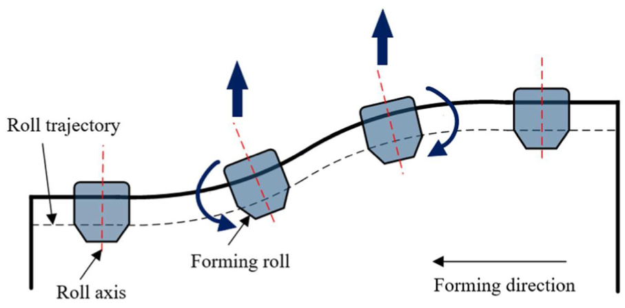
Top view of flexible roll forming.
In flexible roll forming, the metal blank is bent and the flange is longitudinally stretched or compressed. If the required longitudinal deformation in the flange is not sufficient, web warping will occur. Such web warping is a major shape defect that degrades the quality of the product. Many studies have been carried out on shape defects in conventional forming and flexible roll forming.9–12 Bidabadi et al. 13 investigated bowing defects in cold roll forming. Their results showed that the nonuniform distribution of longitudinal strains between the flange and web zones is a major factor in bowing. Safdarian and Naeini 14 investigated the effect of the roll forming parameters on the longitudinal strains and bows of channel section products. Their results show that bowing increases with an increasing bending angle. Park et al. 15 proposed incremental counter forming (ICF) to improve the shape errors. ICF that is combined with flexible roll forming is an effective process for reducing the shape error of the profile in flexible roll forming. Jiao et al. 16 established an analytical model to predict the web warping and longitudinal strain in flexible roll forming. Their results showed that web warping can be observed when the resistance of the flange zone against the stretching and compression in the transition zones is higher than the bending resistance of the web zone. Abvabi et al. 17 investigated the effect of residual stress on bow, springback and end flare. Their results showed that the thickness reduction rolling process decreases the maximum bow height while the springback angle and end flare increase. Woo et al. 18 investigated the effect of intermediate leveling rolls on the reduction of longitudinal bows in flexible roll forming. This research showed that the leveling rolls efficiently reduce the longitudinal bow for thick blanks, whereas edge wrinkles may occur in thin-walled blanks.
In recent years, the demand for semifinal perforated components has increased significantly. 19 The holes can be punched at predetermined positions after forming the initial blank in a product without perforations. In this case, punching the holes in predetermined positions may be difficult owing to deformed geometries. On the contrary, the holes can be made in the first stand of a roll forming line, after which the perforated blank undergoes roll forming operations. In this method, holes can be easily produced at the desired positions with higher reliability.20–22 During the roll forming of perforated blanks, shape defects can be made owing to complex deformation.
Bidabadi et al. 21 investigated the ovality of holes on prenotched channel products in the cold roll forming process. Their results showed the tendency of the ovality of the hole according to the flange width, strip thickness, hole diameter and distances between holes. Watari et al. 23 investigated the characteristic features of shape defects such as edge wave and longitudinal bend in the vertical plane in the cold roll forming of prenotched products.
Currently, there are no experimental or analytical approaches that estimate web warping in the flexible roll forming of perforated products. In order to improve the quality of perforated products using flexible roll forming, it is necessary to analyze the shape defects accurately. The major problem of shape defects during flexible roll forming of perforated blanks is web warping. Web warping is defined as the difference between the vertical heights of these points and the ideal position. 24 Web warping can be divided into two types: longitudinal bow and crossbow, as shown in Figure 2. The longitudinal bow is a deviation across the longitudinal direction of the blank, and the crossbow is a deviation across the width direction of the blank.
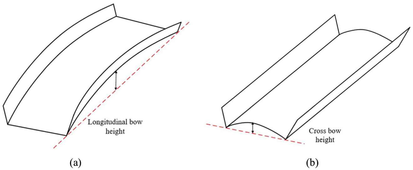
Web warping occurring in roll forming: (a) longitudinal bow and (b) crossbow.
To meet the demands of highly functional parts, high-precision manufacturing technology that can provide sound semifinal perforated components having variable cross sections is frequently required. When a relatively short blank is formed into a variable section by flexible roll forming, web warping such as longitudinal bows and crossbows can be generated in the formed products. In this study, the characteristic features of web warping occurring in the flexible roll forming of perforated blanks was investigated both numerically and experimentally in terms of the shapes of blank and hole orientations of perforated blanks. From the process analysis, a guideline for the perforation of holes in convex, concave and trapezoid blanks is proposed to minimize web warping.
Experiments
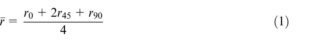
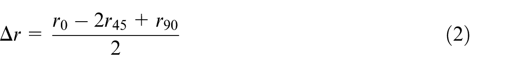
A mild steel known as steel plate cold commercial (SPCC) is used in the experiments. Figure 3 shows the experimentally measured stress–strain curve of the SPCC. From the measured r-values in 0°, 45°, and 90° directions, the normal anisotropy coefficient (
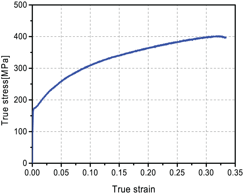
True stress–strain curves of SPCC.
Mechanical properties of SPCC.
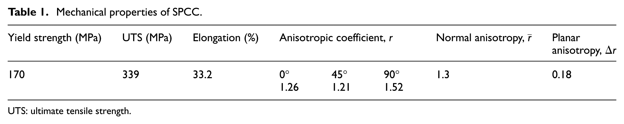
UTS: ultimate tensile strength.
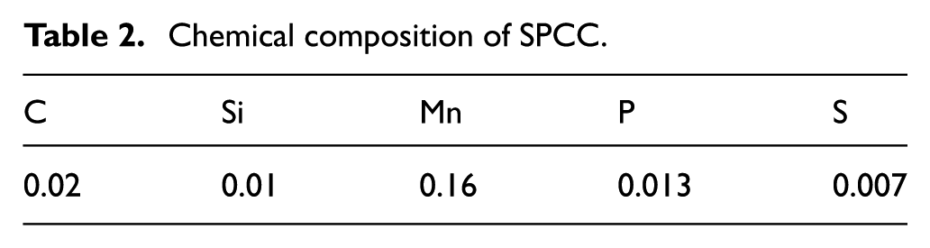
Chemical composition of SPCC.
Three different blanks having convex, concave and trapezoid shapes are analyzed in this study. The geometrical characteristics of the perforated blank are shown in Figure 4. As shown in the figure, L is the length of the blank, W is the flange width, d is the diameter of the holes, b is the distance between the holes, and R is the radius of the blank.
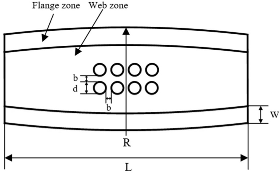
Geometry of perforated blank.
To investigate the longitudinal bow and crossbow for the three different blanks (convex, concave and trapezoid), the orientation direction and positions of the holes are varied. The orientations of the holes are divided into two cases: longitudinal direction and width direction, as shown in Figure 5. The positions of the holes are divided into three cases: top end, middle zone, and tail end, as shown in Figure 6. Initial and formed perforated blanks with longitudinal holes in the middle zone are shown in Figure 7.
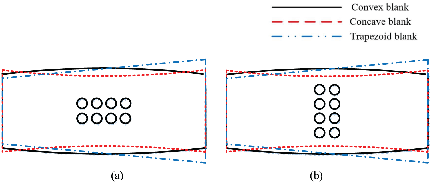
Orientation direction of holes: (a) longitudinal direction and (b) width direction.
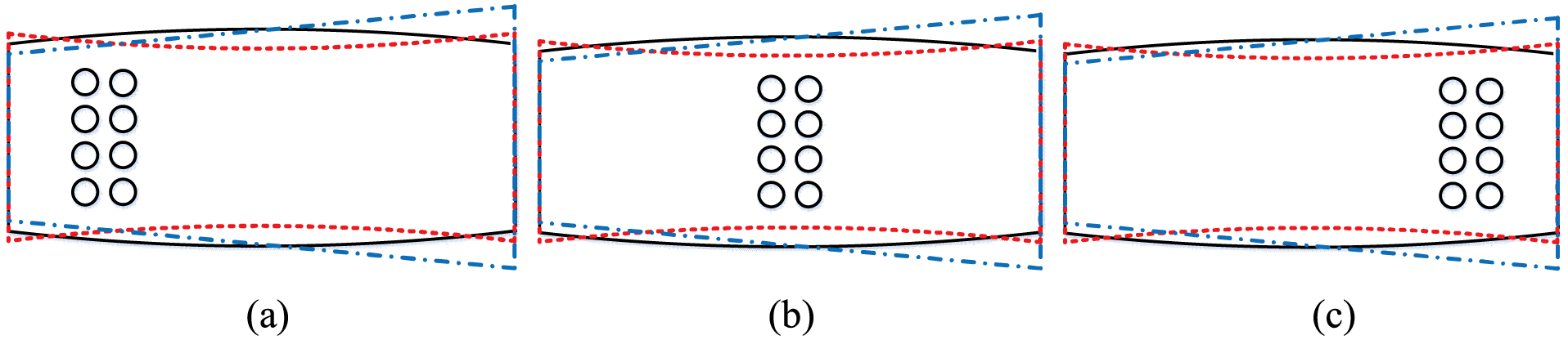
Position of holes: (a) top end, (b) middle zone and (c) tail end.
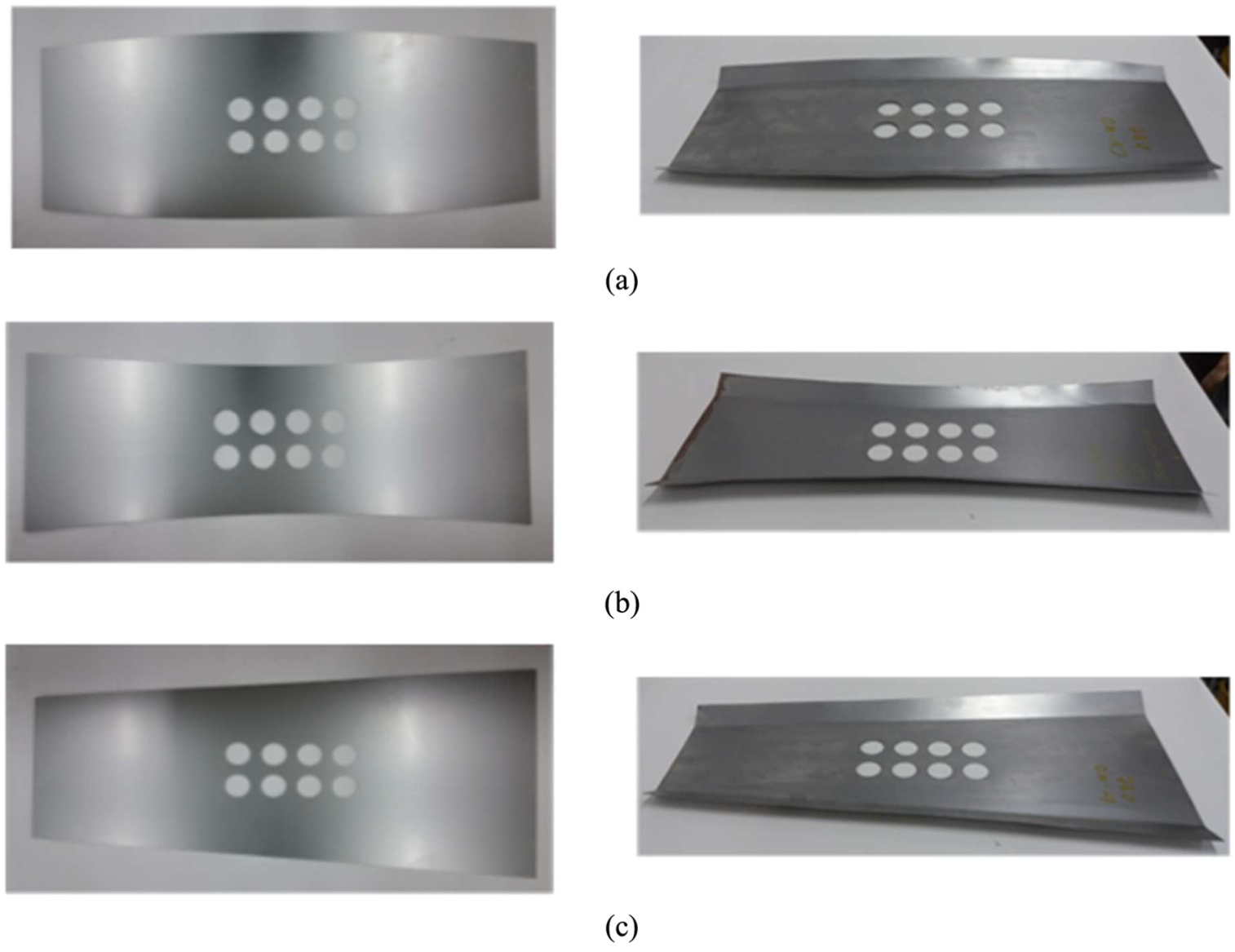
Initial and formed perforated blanks: (a) convex blank, (b) concave blank and (c) trapezoid blank.
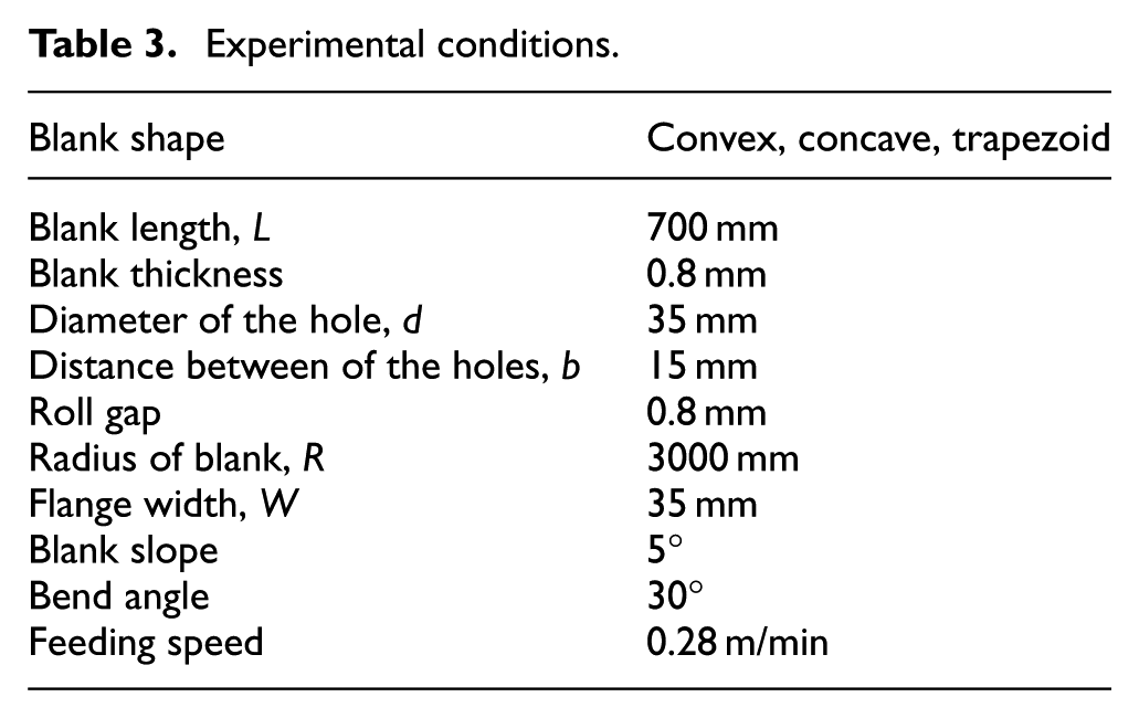
Experiments were conducted on a laboratory-scale flexible roll forming machine, as shown in Figure 8. This flexible roll forming machine has three forming stands. Each forming stand has two forming rolls that can move both axially and rotationally. The machine can produce a profile that has a variable cross section. The forming roll diameter is 70 mm, and the distance between stands is 530 mm. The bending angle is 30°, and the feeding speed of the initial blank is set to be 0.28 m/min. To move the forming rolls in the axial and rotational directions, the forming stands are equipped with servo motors that are controlled by a process computer. Table 3 lists the geometrical dimensions of the blanks and the process conditions of the experiment.
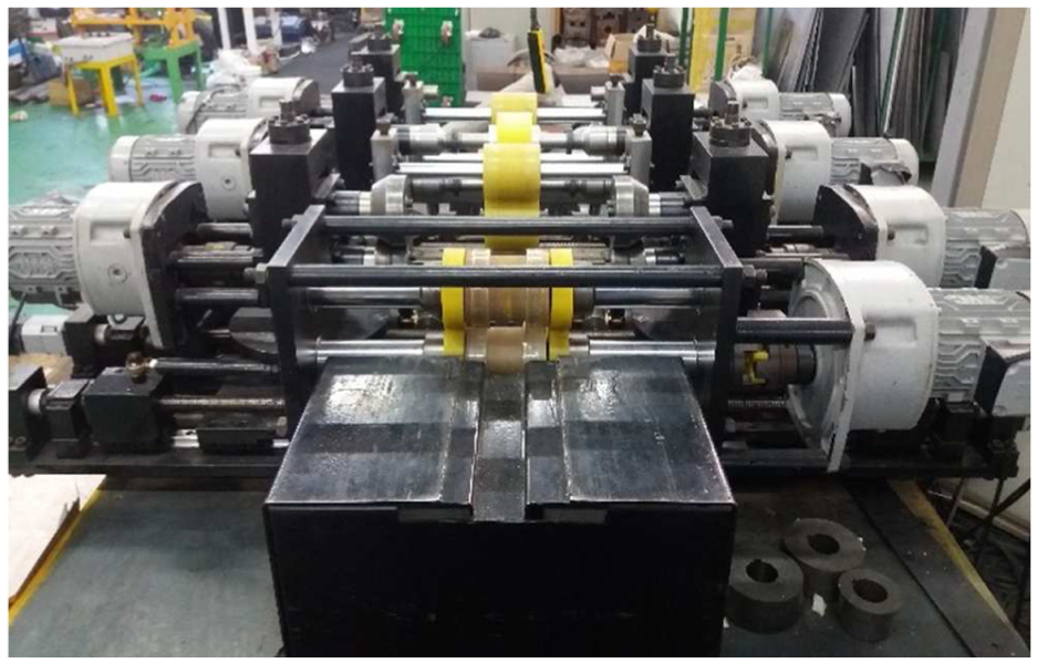
Laboratory-scale flexible roll forming machine.
Experimental conditions.
Finite element simulations
The nonuniform distribution of longitudinal strains between the flange and web zones may cause web warping during the flexible roll forming process. To study the variation of the web warping, it is necessary to investigate the longitudinal and transverse strain distributions that occur in the channel section. It has been reported that the implicit method calculates the strain distribution more accurately than the explicit method because the explicit method is more sensitive to mesh discretization and kinematic operation compared with the implicit method.25,26 Therefore, the finite element (FE) simulations are conducted using the FE code ABAQUS™-Implicit 6.14.
A half geometry model is used in the FE simulation because of the symmetry of the profile. The model includes a forming roll and a blank whose geometries are the same as those used in the experiments. The mechanical properties of the SPCC blank are shown in Table 1. The upper and lower forming rolls are designed as analytically rigid tools because they exhibited negligible deformation. The forming rolls rotate and move vertically along the roll trajectory. The blank is modeled as a deformable part using S4R shell elements, as shown in Figure 9. Both ends of the web are fixed in the Z-direction, and the blank is fixed in the Y-direction. During the simulation, the longitudinal position of the blank was stationary, while the rolls moved over the blank as shown in Figure 10.
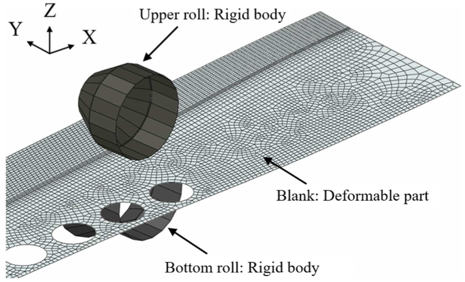
Forming roll pair setup with perforated blank.
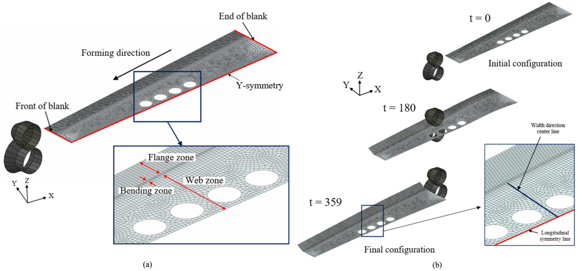
(a) Meshing strategy and (b) flexible roll forming process.
Figure 10(a) shows the mesh density that was used in the blank. A fine mesh of 2 mm × 2 mm is used in the flange zone, and a fine mesh of 1 mm × 1 mm is used in the bending zone because a greater deformation occurs in these zones. A coarser mesh of 2 mm × 5 mm to 10 mm × 5 mm is used in the web zone of the blank. A fine mesh of 5 mm × 5 mm is used around the holes. The contact condition between the blank and the forming roll is enforced by the penalty method. The penalty method approximates hard pressure–overclosure behavior. 27 With this method, the contact force is proportional to the penetration distance, so some degree of penetration will occur. The friction coefficient between the forming roll and the blank is assumed to be zero. According to the research by Bui et al. 28 the friction in the roll forming simulation has no significant influence on the simulation results. Jiao et al.16,29 also worked under the hypothesis that the friction coefficient will not influence the web warping prediction. Since a frictionless condition is used, the constant speed boundary condition is imposed on the top of the blank, and the blank moves into the forming stand so that the blank moves through the forming roll, as shown in Figure 10(b).
The longitudinal bow height in the FE simulation was measured as the vertical distance from the contact plane to the longitudinal symmetry line. The crossbow height was measured as the vertical distance from the contact plane to the width direction center line, as shown in Figure 10(b).
Results and discussion
To investigate the effects of circular holes on the web warping behaviors of perforated blanks, the longitudinal bow and crossbow that occur during flexible roll forming are investigated by both experiments and FE simulations.
Longitudinal bow
To investigate the longitudinal bow in convex blanks, the longitudinal bow height is measured by experimental tests and FE simulations. Figure 11 shows the experimentally observed longitudinal bow for the convex blank.
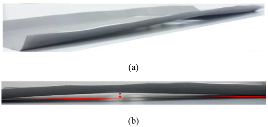
(a) Longitudinal bow and (b) measurement of longitudinal bow.
To understand the effect of holes on the longitudinal bow, the results of FE simulation were analyzed. Figure 12(a) shows how the orientation direction of the holes affects the longitudinal bow height in the convex blank. As shown in the figure, the presence of holes increases the longitudinal bow height. As the holes in the perforated blank reduce the blank’s resistance to deformation, the bow height is increased. 21 When the holes are arranged in the longitudinal direction, the longitudinal bow height is larger than when arranged in the width direction. When holes are arranged in the width direction, the longitudinal bow height decreases in the region where the holes are present.
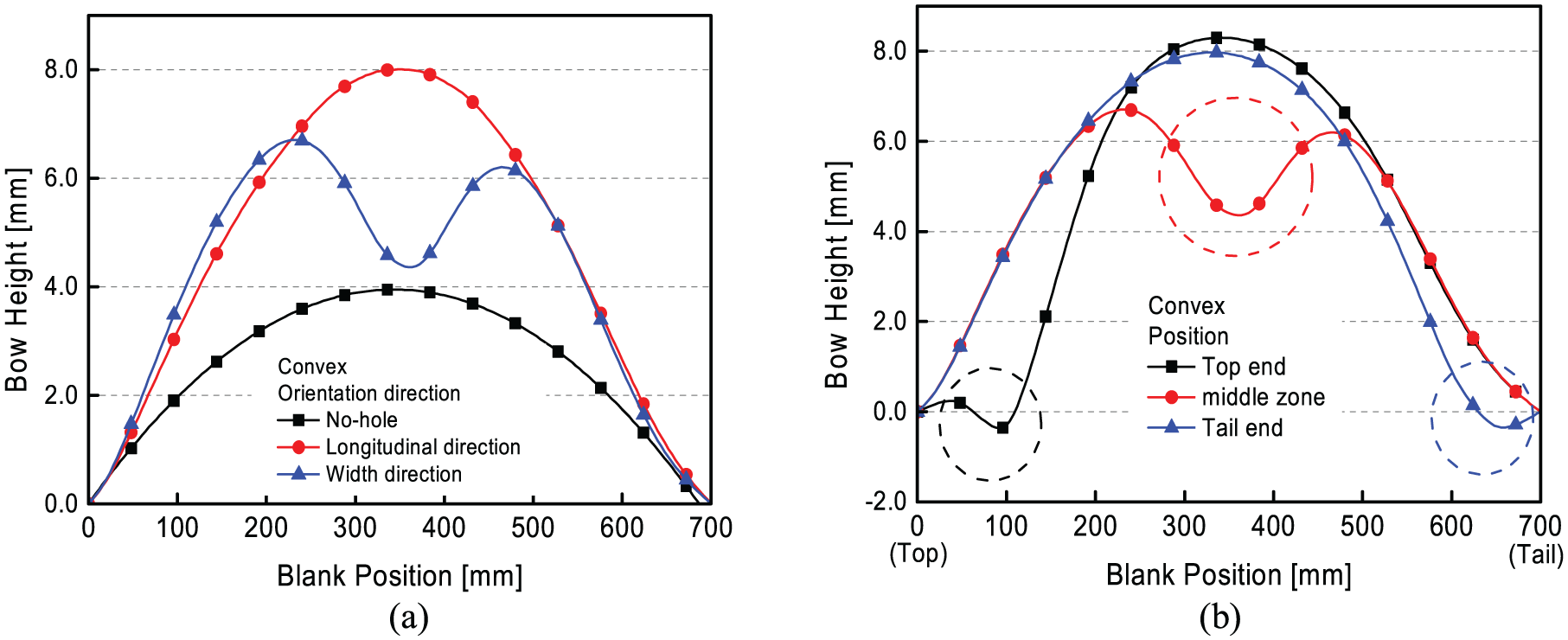
(a) Longitudinal bow height of convex blank according to orientation direction of holes and (b) longitudinal bow height of convex blank according to position of holes.
Figure 12(b) shows how the positions of the holes affect the longitudinal bow height. As shown in the figure, when the holes are located in the top end, the maximum longitudinal bow height is larger than when the holes are located in the middle zone and tail end. It can be seen that the longitudinal bow height decreases locally in the region where the holes are present in all cases.
To further understand the effect of the orientation direction and positions of the holes on the longitudinal bow, the variation in the longitudinal strain at the flange and the web during flexible roll forming is investigated, as shown in Figure 13. The differences in longitudinal strains between the flange and web zone were measured at point A in the flange zone and point B in the web zone. The strain differences along the linear path between A and B points have also been measured. The increasing difference in the longitudinal strains between the web and the edge of the flange leads to a higher longitudinal bow height.17,22 As shown in Figure 14, the longitudinal strain difference between the edge of the flange and the web differs depending on the orientation direction and positions of the holes. The longitudinal strains of the web zone can be approximated to be zero. Therefore, the longitudinal strain differences can be regarded as the longitudinal strain values of the flange zone. That is, the longitudinal strains close to the straight line after the peak point mean the longitudinal strain difference between the flange and the web zones. Figure 14(a) shows that the longitudinal strain difference after forming is larger than when the holes are arranged in the longitudinal direction than when the holes are arranged in the width direction. Figure 14(b) also shows that the longitudinal bow height increases with an increasing longitudinal strain difference. Similarly, the longitudinal strain distributions along the linear path between A and B points show that the longitudinal bow height increases with an increasing longitudinal strain difference as shown in Figure 15(a) and 15(b). Therefore, it can be concluded that these results can explain the variations of longitudinal bow heights according to the orientation direction and position of the holes.
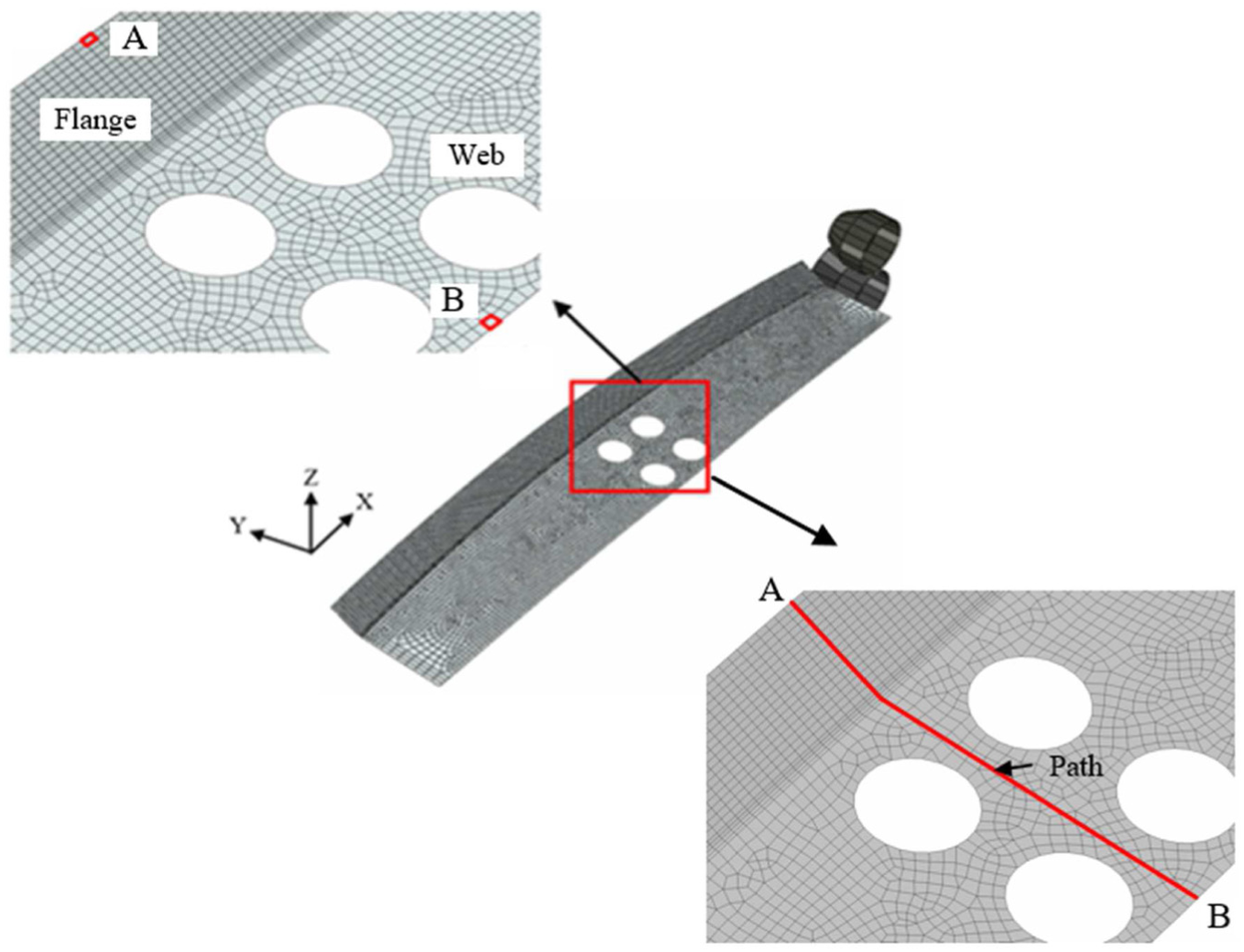
Measurement of longitudinal and transverse strains.
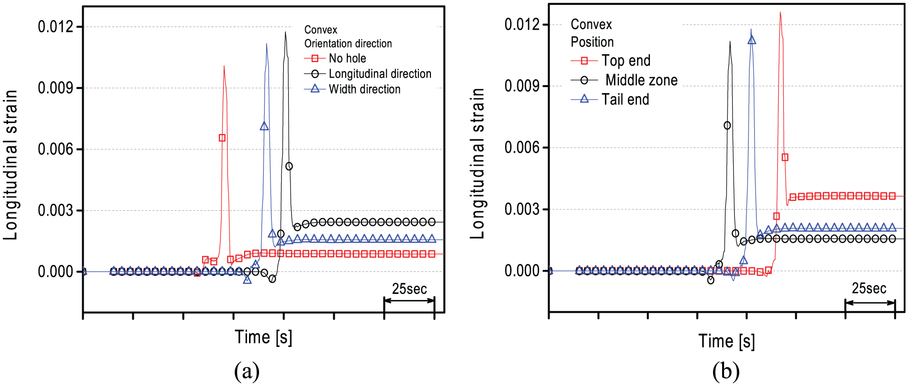
Longitudinal strain: (a) orientation direction of holes for convex blank and (b) position of holes for convex blank.
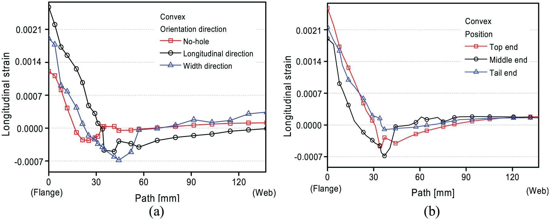
Longitudinal strain in a path starting from flange and ending in web zone: (a) orientation direction of holes for convex blank and (b) position of holes for convex blank.
Figure 16(a) shows how the orientation direction of the holes affects the longitudinal bow height in a concave blank. For concave blanks, a positive longitudinal strain is required at the flange zone. 18 Therefore, unlike the case of convex blanks, the longitudinal bow has a negative value. As shown in the figure, the presence of holes increases the longitudinal bow height as in the case of a convex blank. When the holes are arranged in the width direction, the longitudinal bow height is larger than when arranged in the longitudinal direction. When the holes are arranged in the width direction, the longitudinal bow height increases in the region where the holes are present.
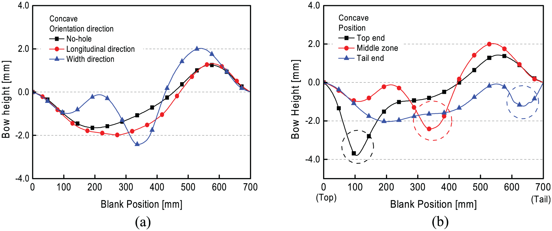
(a) Longitudinal bow height of concave blank according to orientation direction of holes and (b) longitudinal bow height of concave blank according to position of holes.
Figure 16(b) shows how the positions of holes affect the longitudinal bow height. As shown in the figure, when the holes are located in the top end, the maximum longitudinal bow height is larger than when the holes are located in the middle zone and tail end. When the holes are located in the top end, middle zone and tail end, the negative longitudinal bow height increases locally in the region where the holes are present.
Figure 17(a) shows how the orientation directions of the holes affect the longitudinal bow height in a trapezoid blank. As shown in the figure, the presence of holes increases the longitudinal bow height as in the cases of convex and concave blanks. When the holes are arranged in the width direction, the longitudinal bow height is larger than when arranged in the longitudinal direction. When the holes are arranged in the width direction, the longitudinal bow height increases sharply in the region where the holes are present, as shown in the figure. Figure 17(b) shows how the positions of the holes affect the longitudinal bow height. As shown in the figure, when the holes are located in the middle zone, the longitudinal bow height is larger than when the holes are located in the top end and tail end. When the holes are located in the top end, the longitudinal bow height decreases locally in the region where the holes are present. Conversely, when the holes are located in the middle zone, the longitudinal bow height increases locally. Owing to the gradually increasing shape characteristics of the trapezoid blank, the holes in the tail end are far from the flange zone, so there is no local variation in the longitudinal bow height.
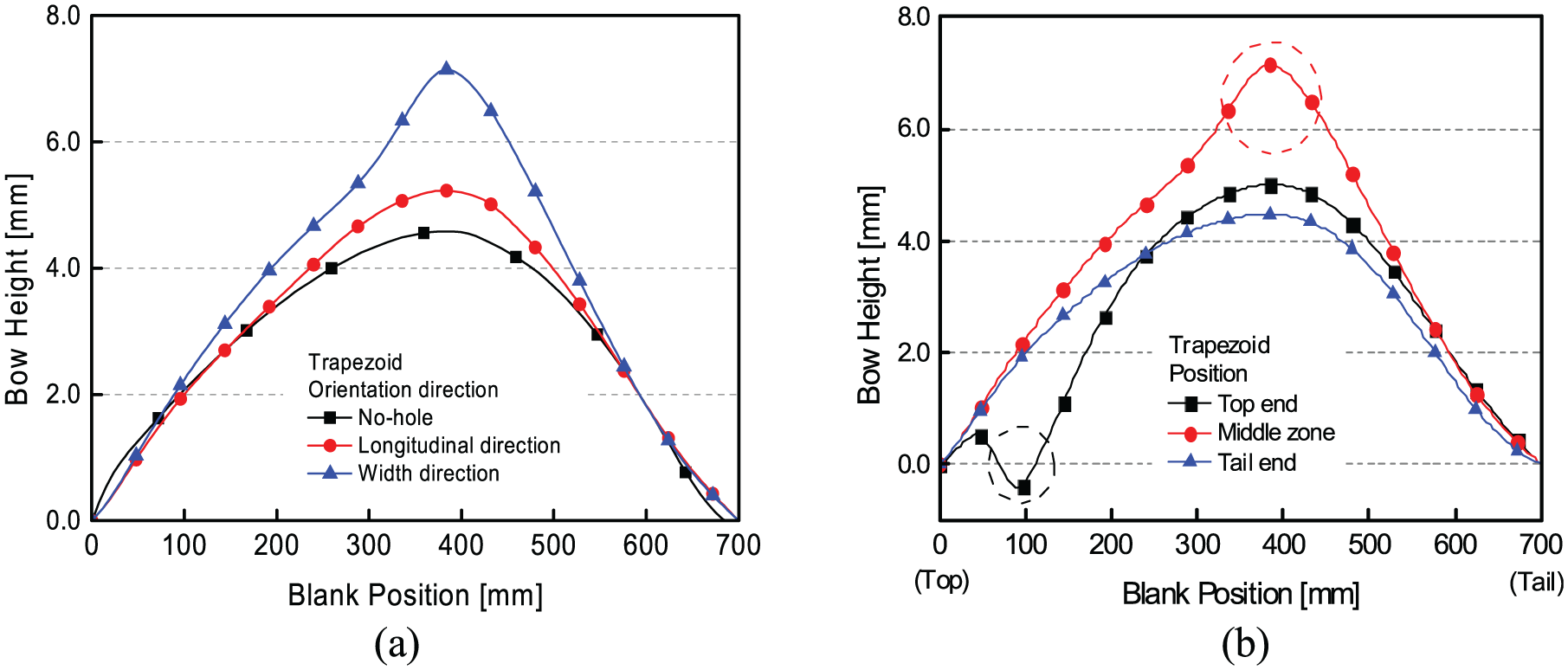
(a) Longitudinal bow height of trapezoid blank according to orientation direction of holes and (b) longitudinal bow height of trapezoid blank according to position of holes.
Figure 18 compares the longitudinal bow heights obtained from the experiments and simulations. The figure shows the maximum longitudinal bow height according to the orientation direction and the positions of the holes for three different blanks. It can be seen that the experimental results and the simulation results have almost the same tendency. Therefore, the simulation results obtained in this study are reliable and are applicable in the design of actual shop-floor operations.
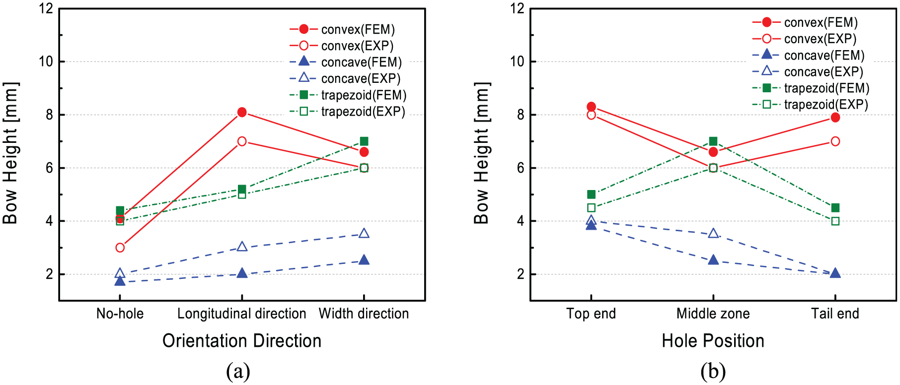
(a) Maximum longitudinal bow height according to orientation direction of holes and (b) maximum longitudinal bow height according to position of holes.
Crossbow
To investigate the crossbow for convex blanks, the crossbow height is measured by an experimental test and FE simulation. Figure 19 shows the experimentally observed crossbow for a convex blank.
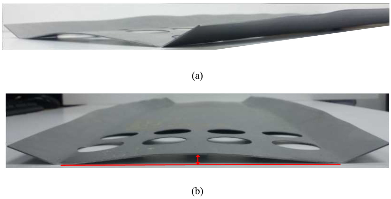
(a) Crossbow and (b) measurement of crossbow height.
To understand the effect of holes on the crossbow, the results of FE simulation were analyzed. Figure 20(a) shows how the orientation directions of the holes affect the crossbow height in the convex blank. As shown in the figure, the presence of holes increases the crossbow height. As the holes in the perforated blank reduce the blank’s resistance to deformation, the crossbow height increases in the same manner as the longitudinal bow. When the holes are arranged in the width direction, the crossbow height is larger than when the holes are arranged in the longitudinal direction. As can be seen in Figure 20(a), the crossbow height increases sharply when the holes are arranged in the width direction.
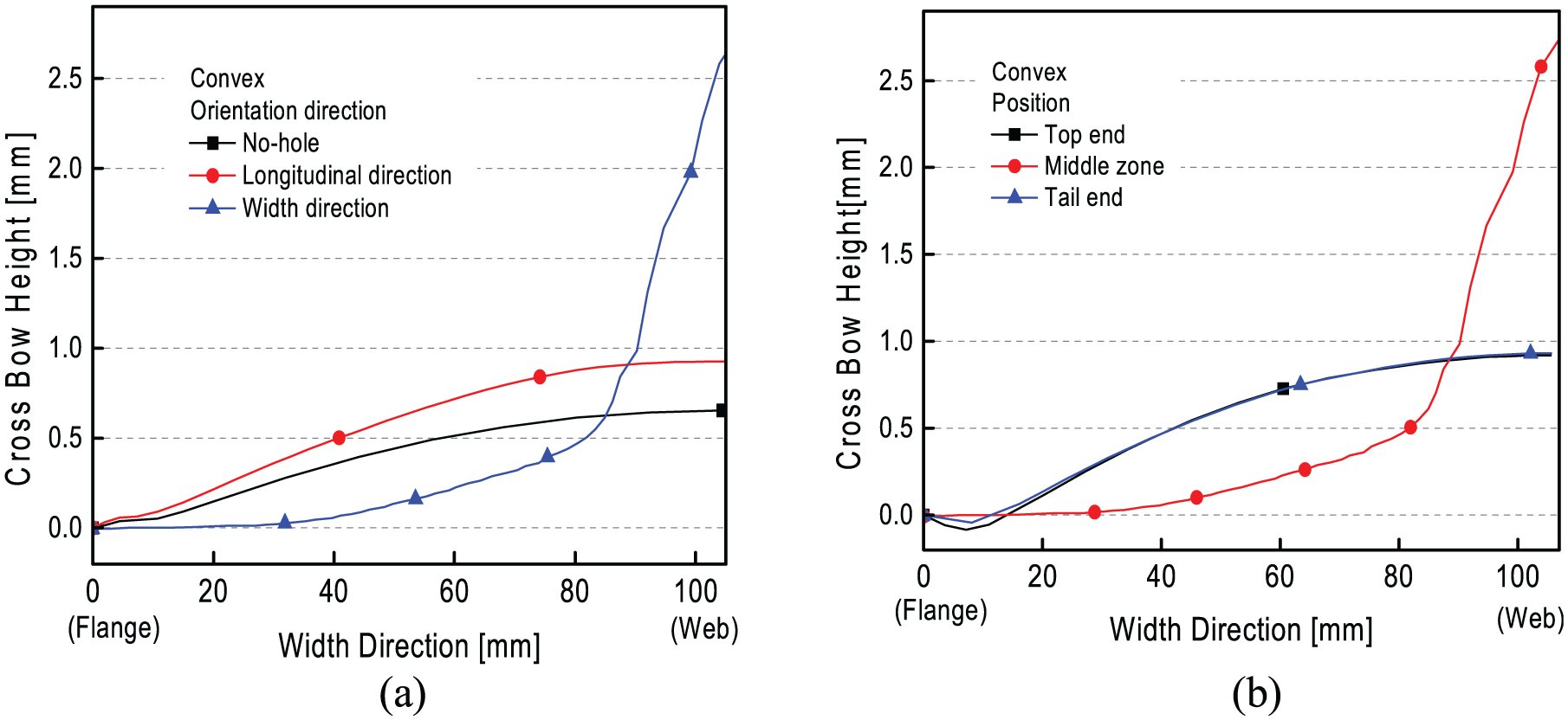
(a) Crossbow height of convex blank according to orientation direction of holes and (b) crossbow height of convex blank according to position of holes.
Figure 20(b) shows how the positions of the holes affect the crossbow height. As shown in the figure, when the holes are located in the middle zone, the crossbow height is larger than when the holes are located in the top end and tail end. Similar to the case where the holes are arranged in the width direction, the tendency of the crossbow height increases sharply when the holes are located in the middle zone, as shown in Figure 20(b). When the holes are located in the top end and tail end, there is no significant effect on the crossbow height.
Crossbow defects occur because of the nonuniform distribution of the transverse strain across the cross section of the roll formed product. It can be seen that the crossbow increases as the difference in the transverse strains between the flange and the web increases. In order to understand the effect of the orientation direction and the positions of the holes on the crossbow, the variation in the transverse strains at the edge of the flange and the web during flexible roll forming is investigated. The transverse strains at the flange and the web were measured at both ends of the perforated area, as shown in Figure 13. Figure 21 shows the transverse strains in the flange zone of the convex blank. As shown in Figure 21(a), the transverse strain difference after roll forming is larger when the holes are arranged in the width direction than when the holes are arranged in the longitudinal direction.
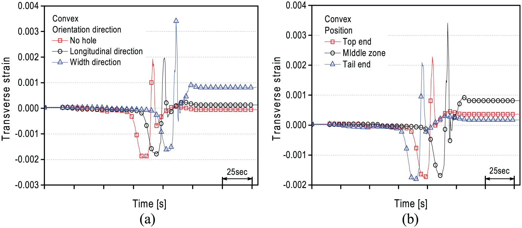
Transverse strain: (a) orientation direction of holes for convex blank and (b) position of holes for convex blank.
As shown in Figure 21(b), the transverse strain difference after roll forming is larger when the holes are located in the middle position than when the holes are located in the top end and tail end. Unlike the longitudinal bow tendency, the crossbow is largest when the holes are arranged in the width direction and are located in the middle zone, regardless of the blank’s shape. Figure 22 shows the maximum crossbow height according to the orientation direction and the positions of the holes for three different blanks. It can be seen that the experimental results and the simulation results have almost the same tendency. The crossbow has the same tendency for convex, concave and trapezoid blanks, as shown in Figure 22.
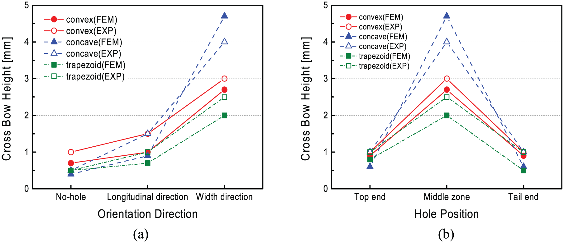
(a) Maximum crossbow height according to orientation direction of holes and (b) maximum crossbow height according to position of holes.
Recommended perforating guide
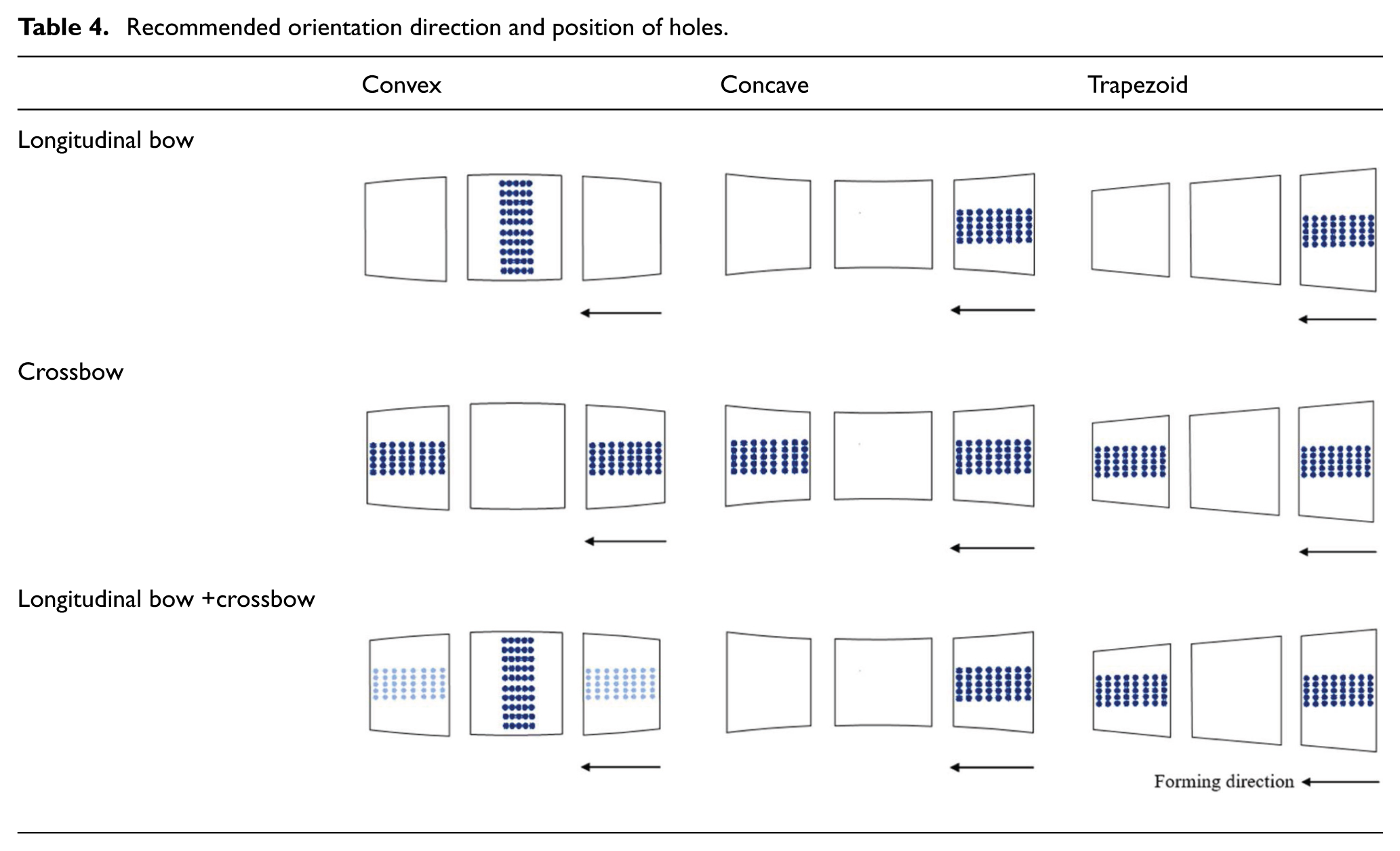
From the analysis results, a guideline for the perforation of holes in a blank is proposed to reduce the web warping. Table 4 shows the recommended directions and positions of the holes to minimize both the longitudinal bow and crossbow. For a convex blank, the two areas that can minimize the longitudinal bow and crossbow do not overlap. Therefore, if there is a need to consider a longitudinal bow, holes can be located in the width direction in the middle zone and in the longitudinal direction at the top and tail ends if it is necessary to consider a crossbow. For a concave blank, positioning the holes’ longitudinal directions at the top end can reduce the longitudinal bow and crossbow. For a trapezoid blank, positioning the holes in the longitudinal direction at the top and tail ends can reduce the longitudinal bow and crossbow.
Recommended orientation direction and position of holes.
Conclusion
The characteristic features of web warping occurring in the flexible roll forming of perforated blanks was investigated both numerically and experimentally, and the following conclusions were obtained:
Longitudinal bow and crossbow are primarily caused by the nonuniformity of longitudinal and transverse strains between the flange and the web. In the case of a perforated blank with holes, the degrees of the longitudinal bow and crossbow are intensified owing to the increased differences in the longitudinal and transverse strains between the flange and the web.
The longitudinal bow and crossbow in perforated blanks can be reduced by decreasing the differences in the longitudinal and transverse strains through the proper design of the directions and positions of the holes.
For a convex blank, the longitudinal bow height can be reduced by orienting the holes in the width direction and locating the holes in the middle zone. For concave and trapezoid blanks, the orientation of the holes in the longitudinal direction and location of the holes in the tail end can reduce the longitudinal bow height. Locating the holes away from the flange zone can reduce a wavy longitudinal bow.
For convex, concave and trapezoid blanks, the crossbow height tends to increase when the holes are oriented in the width direction and located in the middle zone.
From a process analysis, a guideline for the perforation of holes in a blank is proposed to reduce web warping.
Footnotes
Declaration of conflicting interests
The author(s) declared no potential conflicts of interest with respect to the research, authorship and/or publication of this article.
Funding
The author(s) disclosed receipt of the following financial support for the research, authorship, and/or publication of this article: This research was supported by the Basic Science Research Program through the National Research Foundation of Korea (NRF) funded by the Ministry of Education (No. 2016R1D1A3B03931174).