
Abstract
Bending process is very important for the mechanical performance of large-scale forgings. Unfortunately, the bending mechanism and failure control remain poorly understood until now. In this work, the bending processes of the forged coupler yoke which is a typical large-scale forging are comparatively evaluated. A novel multi-stage bending process is proposed to overcome defects such as fracture, scratches and local thinning occurred during the initial bending process. Based on the comparative study on deformation and failure behaviors of conventional and newly proposed processes, the multi-stage bending mechanism was deeply analyzed. Furthermore, to obtain the optimum die design, the Kriging surrogate models and the genetic algorithm were adopted to optimize the primary evaluation indexes of bending performance. Finally, the presented bending process and optimal die design were further validated by trial production. The results show that the newly proposed bending process is an efficient and low-cost method for enhancing the bending quality of large-scale forgings.
Keywords
Introduction
Coupler yoke is used to connect two wagons, transfer axial loads (compressive and tensile) and damp the impacts during the freight cars or locomotives running or delivery, which is a typical large-scale component with high ribs and thin webs. As one of the most critical components of coupler buffer device, it plays an essential role for the safety and efficiency of railway transportations. 1 The manufacturing process and mechanical properties of coupler yoke pose significant influence on the amount of employed load and permissible speed of wagons. Nowadays, the mainstream manufacturing process of the forged coupler yoke is unfolded hot forming and then bending into a U-shape (as shown in Figure 1(a)). Nevertheless, the bending process has become the primary focus of the above-mentioned manufacturing strategy. Using the conventional die design, forged coupler yokes are vulnerable to bending defects such as cracks, surface scratches, local thinning and arm fracture,2,3 as shown in Figure 2. In order to overcome the technical difficulties, most manufacturers resort to the exclusive and expensive bending machine to perform the process which is time- and cost-consuming and always results in the available press halted and idled. So is it possible to develop a novel bending process for large-scale forgings which can be readily performed on general presses and fully understand the bending mechanism to obtain the defect-free bending parts?
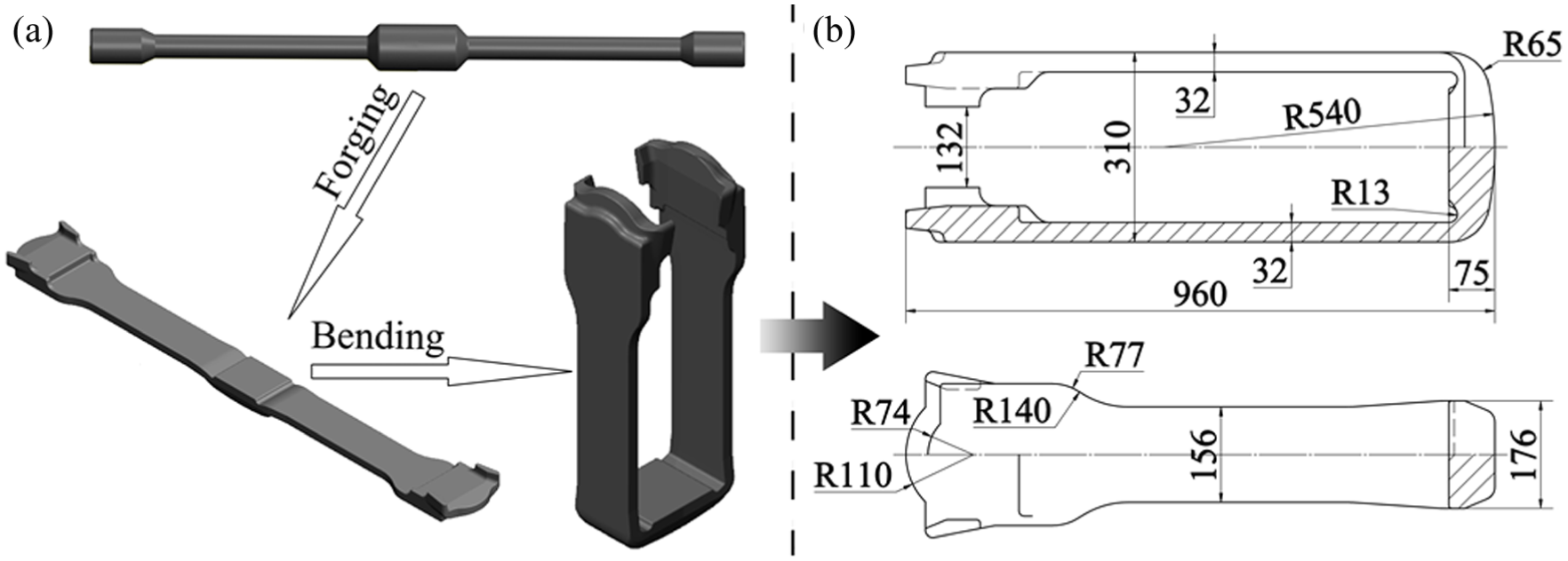
(a) The mainstream manufacturing process and (b) the main geometric dimensions of the bended coupler yoke.
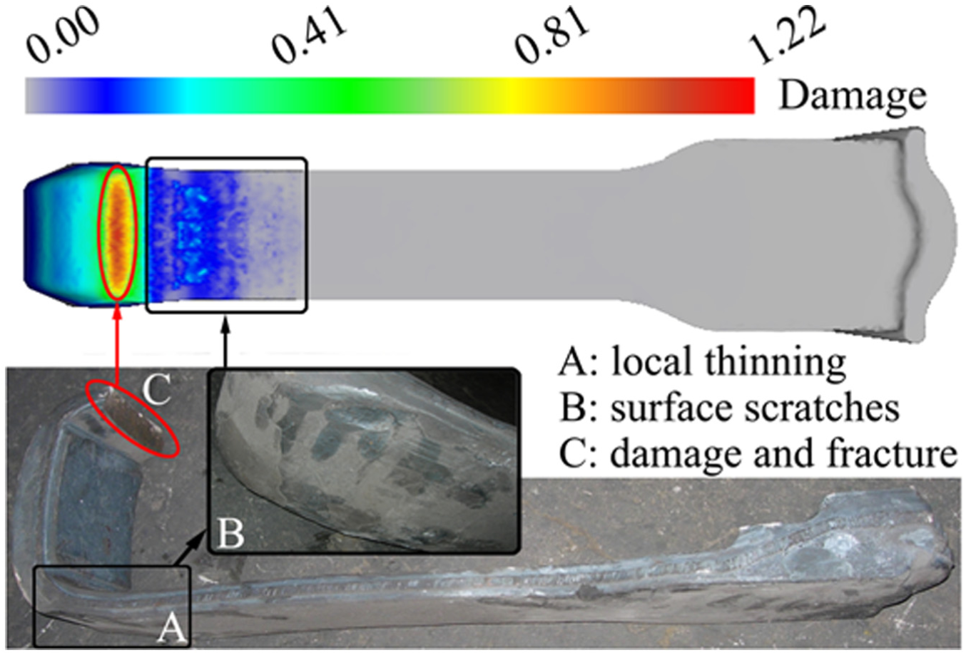
The defects in the initial bending.
As for the die design and optimization, the metamodeling and optimization methods, which are also called as surrogate-assisted optimization, have been extensively applied in laboratories and industries due to the high efficiency and feasibility in dealing with the strong nonlinear, high-dimensional and large-scale metal forming problems.4–6 Zhao performed a multi-objective optimization for porthole extrusion die based on Kriging metamodeling and Pareto-based genetic algorithm (GA) to decrease the die stress and mandrel deflection and even the velocity distribution in the cross section of the profile. 7 Sun 8 investigated the effects of geometry of second-step welding chamber of the extrusion die on the standard deviation of the velocity field in bearing exit and obtained the optimum parameter set by combining Box–Behnken experimental design with response surface method. Okada 9 proposed a method for determining optimal back-pressure profile in forging of aluminum alloy using the radial basis function surrogate and multi-objective optimization to improve the mold filling as well as reduce the forming energy. Hassan et al. 10 optimized the cold forward extrusion die by integrating the artificial neural network metamodeling with GA. Based on the design of experiment (DOE), the function between the design variables and the surrogate model is established implicitly and then the optimization algorithms are applied to solve the function and finally the optimum design variables are obtained within the mapping range. Consequently, the surrogate-assisted optimization is obviously a feasible and robust method in die design optimization.
Most of the current works are focused on studying the crack initiation and propagation mechanism of coupler yokes in service and springback control in sheet metal bending.11–13 However, there is no previous detailed study on process design, bending mechanism and die optimization for coupler yokes bending. In this article, based on the failure analysis of the initial bent coupler yoke with the conventional die design, a novel multi-stage bending process is proposed. Furthermore, the bending mechanism of the newly proposed process is deeply analyzed. The physical properties and the constitutive relationship of the type E steel 25MnCrNiMoA (a Chinese steel grade) which was widely used in forged coupler yokes were determined and implemented in the finite element (FE) software first. Then, based on the DOE technique, the Kriging surrogate model was established to approximate the relationship between parameters of the newly developed bending process and the main evaluation indexes of bending performance. Finally, the GA was employed to calculate the optimum input values of the established surrogate model, and the optimized combination of parameters for the newly proposed multi-stage bending process was successfully achieved.
Materials and methods
Description of component and models
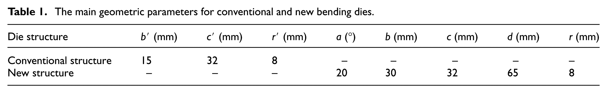
The main geometric dimensions of the bended coupler yoke are depicted in Figure 1(b). The mass is about 110 kg and its unfolded length is approximately 2030 mm. The coupler yoke is a typical U-shaped workpiece and the design thickness of the bended arm is 32 mm (30 mm after machining), which is much thicker than that of conventional bending sheet. Figure 3(a) and (b) illustrates the schematic structure of the initial and newly proposed die design, respectively. b′ is the radius of the die entrance, c′ and c are the clearance between the punch and die, r′ and r are the radius of the punch fillet, a is the slanting angle, b is the diameter of the lower roller and d is the diameter of the upper roller. The values of geometric parameters are listed in Table 1. It is worth illustrating that three or more rollers can be added in the proposed die design, but in order to simplify the model and optimization parameters, the two-roller model was selected.
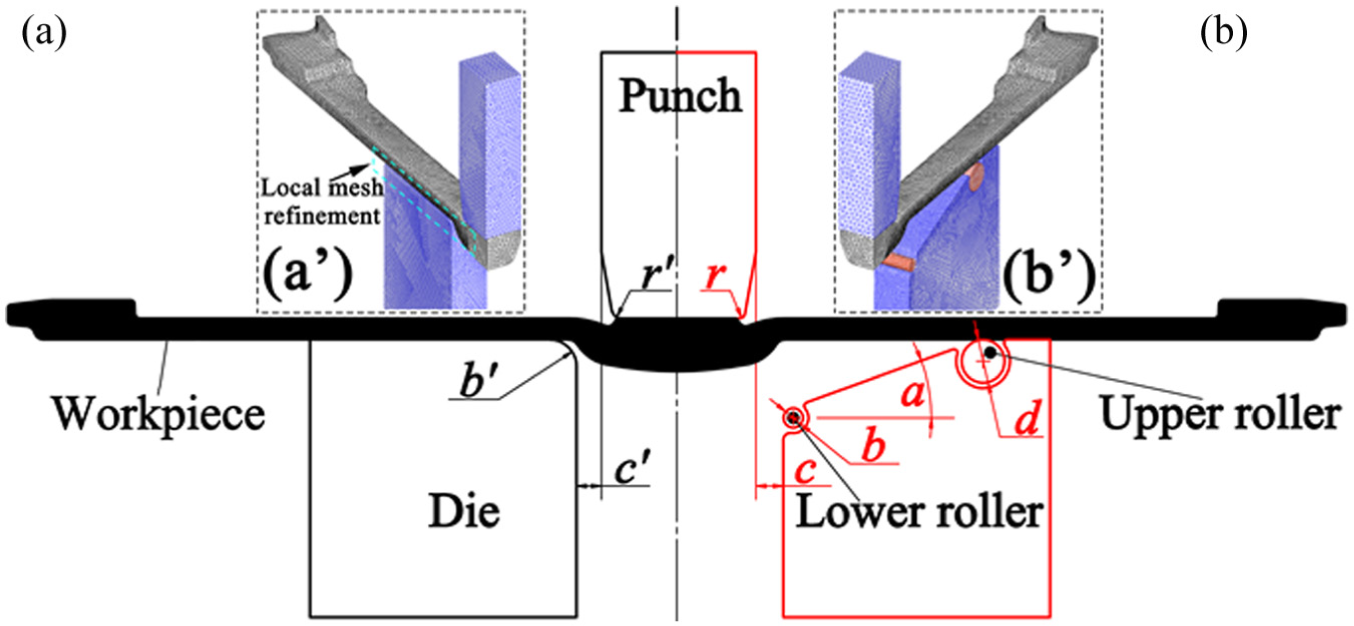
The schematic structure of (a) conventional and (b) new die designs.
The main geometric parameters for conventional and new bending dies.
Material model
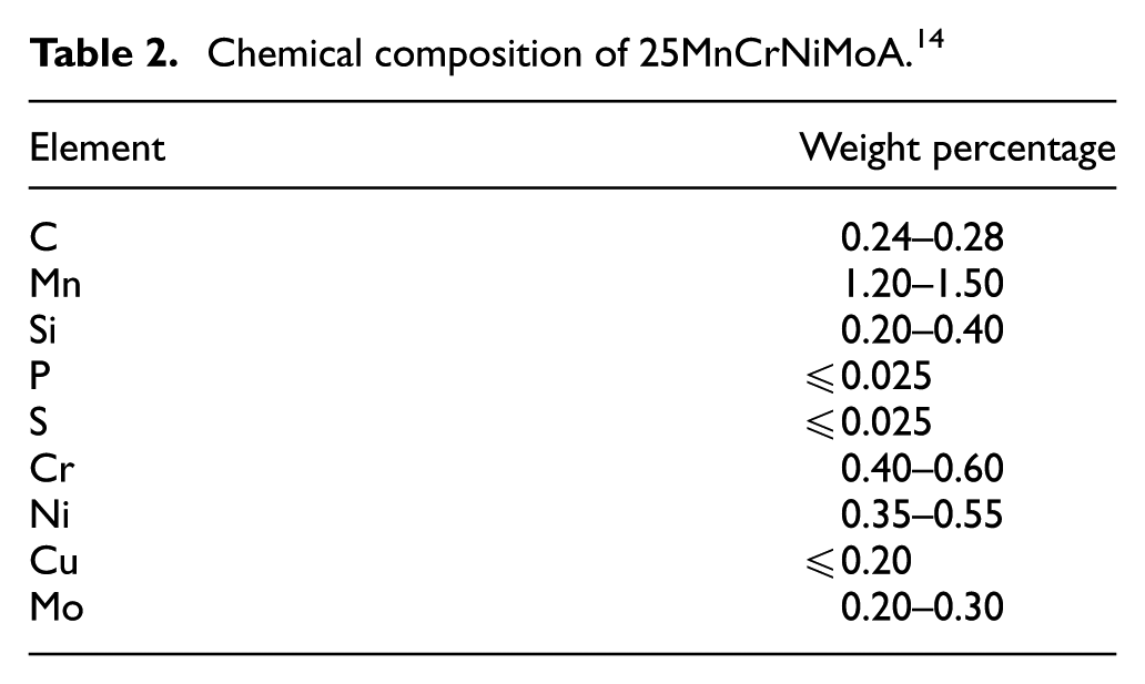
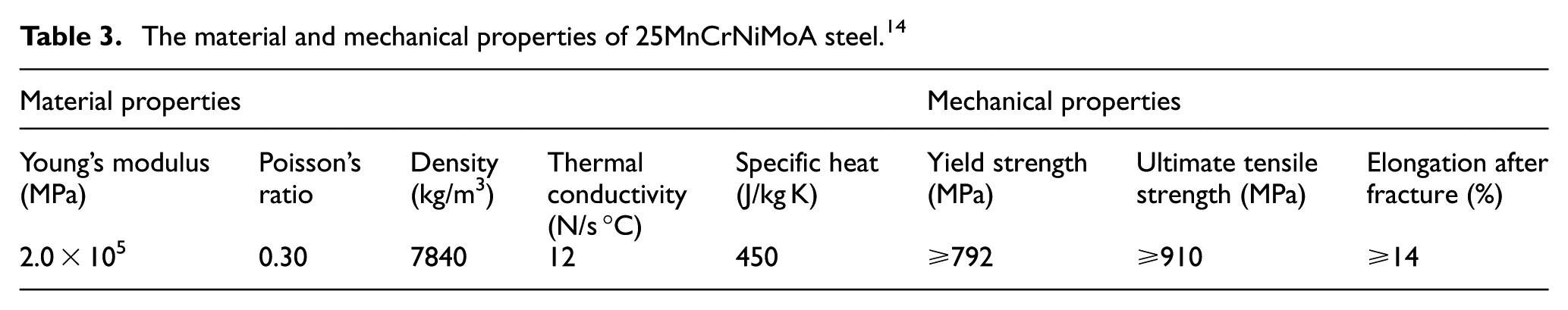
The high-strength low-alloy steel 25MnCrNiMoA which is exclusively used in forged coupler yokes in China is equivalent to the Association of American Railroads (AAR) type E steel, according to the tensile strength after heat treatments. The chemical composition and material properties (Young’s modulus, Poisson’s ratio, density, thermal conductivity and specific heat) and the mechanical properties (the yield strength, ultimate tensile strength and elongation after fracture) of 25MnCrNiMoA steel were found in reference 14 and the detailed values are listed in Tables 2 and 3, respectively. To facilitate the numerical simulation, the flow stress data of the studied material were obtained from the uniaxial compression testing, as shown in Figure 4. A computer-controlled, servo-hydraulic Gleeble 1500 machine was used for compression testing. The specimens were resistance heated at a heating rate of 10 °C/s and held at the initial deformation temperatures (800, 900, 1000, 1100 and 1200 °C) for 180 s. The homogenized ingots were scalped to a diameter of 10 mm and height of 12 mm with grooves on both sides filled with machine oil mingled with graphite powder as lubrication to reduce friction between the anvils and specimen during isothermal hot compression tests at strain rates of 0.1, 1 and 10 s−1.
Chemical composition of 25MnCrNiMoA. 14
The material and mechanical properties of 25MnCrNiMoA steel. 14
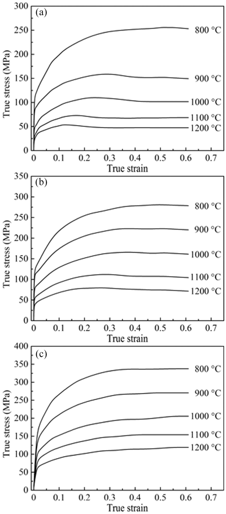
True stress–true strain curves of 25MnCrNiMoA at different temperatures and strain rates: (a) 0.1 s−1, (b) 1 s−1 and (c) 10 s−1.
Finite element model setup
As shown in Figure 3(a′) and (b′), the three-dimensional (3D) FE models of the bending processes were developed by the CAE software DEFORM-3D. And, the following assumptions were made in this study for simplifying the simulation: (1) material model of the workpiece is rigid-viscoplastic, (2) tools and complementary instruments are rigid but non-isothermal, (3) a quarter of the model is analyzed due to the symmetric geometry, (4) friction coefficients are constant and (5) thermal properties of the workpiece and bending tools are constant. Moreover, the tetrahedral elements with a varying mesh density (higher in anticipated contact areas, as shown in illustration a′ of Figure 3(a)) were used to save computational time without compromising accuracy. The punch was assigned as the primary die and moved downward with a speed of 150 mm/s. The sliding friction coefficients between the hot workpiece and the punch/die were set as 0.3, which is a default value in DEFORM-3D on the condition of steel hot forming with lubricants. The rollers were driven rotated in the same direction. Furthermore, the Cockcroft and Latham damage criterion was selected to evaluate the magnitude of the damage during bending. And, the maximum wear depth in lower rollers was employed to estimate the die service life in this investigation and the value could be read directly in the DEFORM post-processor. The modified Archard’s wear equation is used to predict die wear depth, 15 which can be expressed as follows
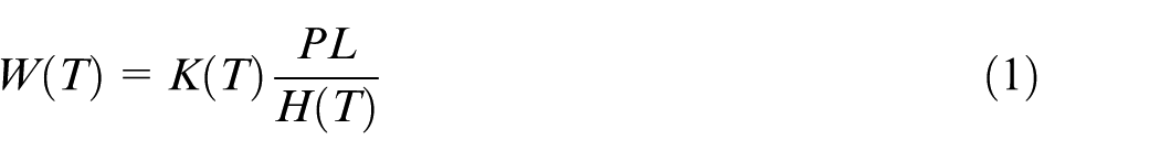
where W(T) is the wear depth of the die surface, L is the sliding length, P is the local pressure and T is the domain temperature. The hardness H(T) and the wear coefficient K(T) of the die material H13 were acquired from the literature 15


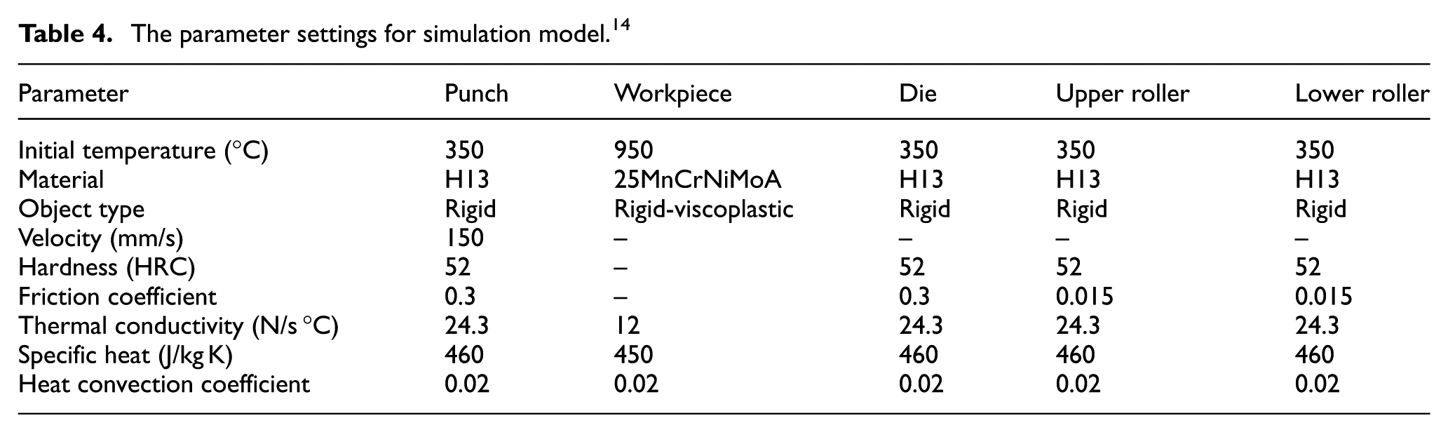
It is worth illustrating that we evaluated the wear depth by one simulation run due to the extremely time-consuming computations, which may simplify the calculations and maintain the overall tendency of the maximum wear depth in rollers without essentially accuracy loss. Given that no obvious springback was observed in trial production, the elastic recovery was not considered in this study. In addition, heat transfer was taken into account and the thermal parameters including the heat convection coefficient, the specific heat and the heat convection coefficient were considered and implemented in the FE model. The specific parameter settings for the FE simulations are shown in Table 4.
The parameter settings for simulation model. 14
Optimization procedures
In this work, a surrogate model assisted optimization approach is utilized to obtain the optimal design of the new bending die. The whole optimization process consists of three steps: designing of experiment (DOE), establishing the Kriging metamodel and executing the GA optimization. The Latin hypercube sampling (LHS) technique was used to perform the DOE design. 16 The Kriging model was established using Dace toolbox of MATLAB software. 17 And, the GA was introduced to the established Kriging model for optimization calculation. The flow chart of the optimization process is shown in Figure 5.
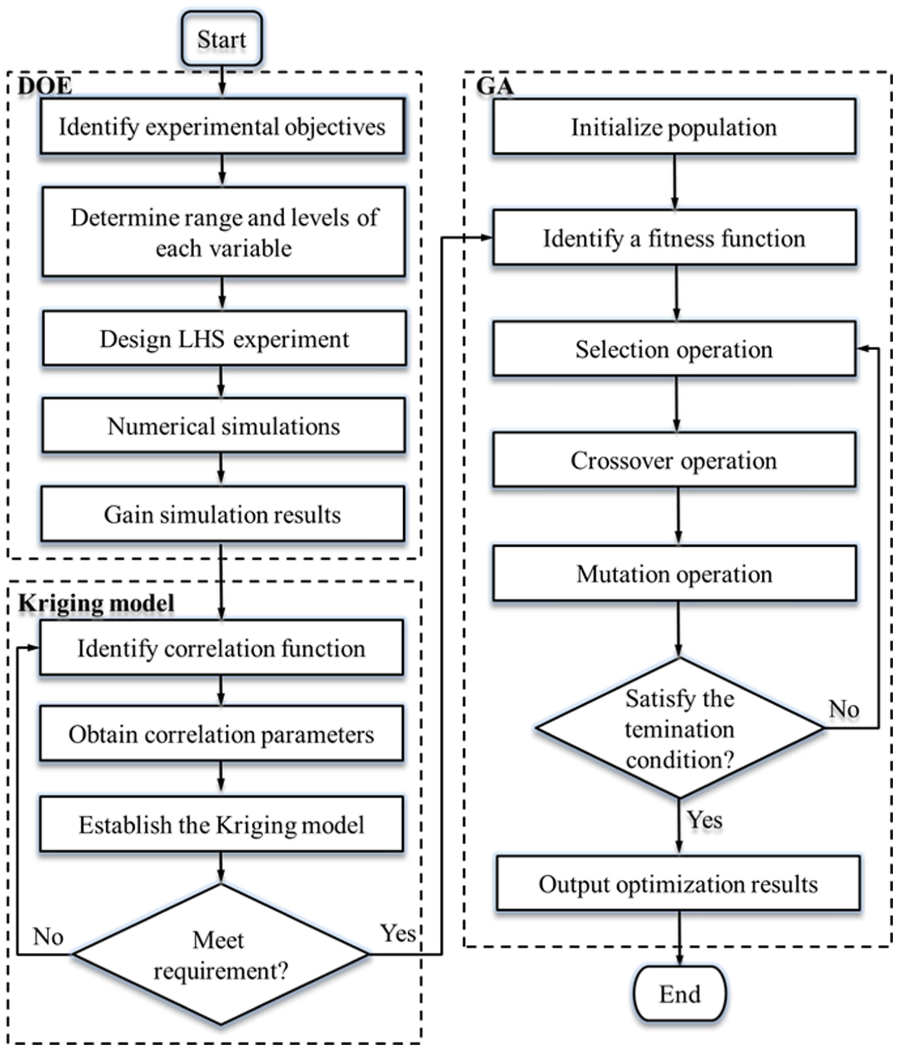
The flow chart of the optimization process.
Failure analysis and new die design
Failures in initial bending process
Excessive and unsteady bending load
Figure 6 exhibits the relationship between the bending load and the punch strokes during conventional (top in black) and newly proposed (bottom in red) bending processes using the established numerical model. It is clear that the load curve of the conventional die design increases sharply at the first forming steps and then reaches its maximum value of 220.56 kN, but decreasing gradually afterward. The maximum bending force during the initial bending process is about 1.60 times of that in the newly proposed process. The undue bending load mainly leads to the excessive energy consumption and wear in die fillets, which does not facilitate to improve the service life of the bending die. Furthermore, the wide range between the maximum and minimum load values in the forming history is pronounced, which indicates the bending process is rather unsteady and the working force fluctuates substantially. It could be further verified that the standard deviation of the bending load is 54.56 kN during the conventional bending, which is about 1.21 times of that in the newly proposed process. Therefore, the maximum bending force and the uniformity of bending load should be used as two important optimization indexes.
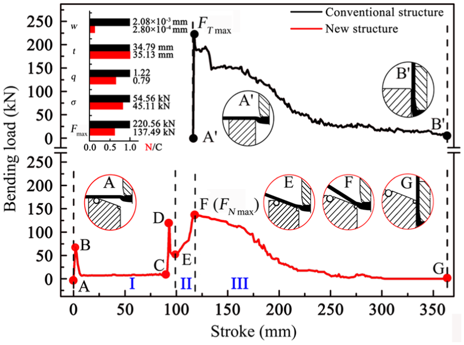
The load history of conventional and new bending processes.
Cracks and fracture at the arm root
The history of material damage, which may eventually affect the material mechanical properties, is considered as one of the most important factors inducing the crack propagation of forgings. As shown in Figure 2, the trial production and simulation results reveal that the arm root of the forged coupler yoke is the fracture risk zone during bending. According to the simulation results of the maximum damage history at arm root in conventional bending processes, the material damage increases rapidly at the initial stage and then reaches the maximum damage value of 1.22, which is about 1.54 times of that in the newly developed process. The rapid rise of the maximum damage value improves the tendency of the local stress concentration. Therefore, the maximum damage at arm root should be adopted as another optimization index.
Surface scratches and local thinning
As demonstrated in Figure 2, the local thinning (zone A in Figure 2) and scratches (zone B) occur during bending, which reveals that the stretched region undergoes a severe tensile stress and the exterior surface contacted with die fillet slides over it causing a thinning in zone A. Simulation results illustrate the fact that a small amount of metal at the arm root flows along the length of the yoke arm due to the characteristic that transverse metal flowing rarely occurs in the plate with a width of three times greater than its thickness during free bending. Along with the punch moving down into the cavity, an intense compressive stress squeezes the contacted metal and widens the bending region, which makes a further thinner bending region. Consequently, the inlet fillet radius and the clearance between punch and die should be optimized to prevent from surface scratches and local thinning. And, the local thinning should be considered as an optimization index.
Excessive die wear
As an important evaluation index, die wear poses a significant effect on die service life and cost. In this study, the maximum wear depth is investigated on the fillet of the die because of the relative motion between workpiece and die. Therefore, the maximum wear depth should be selected as an optimization index.
New die design and mechanism analysis
In order to overcome the above-mentioned defects, a novel multi-stage bending method was proposed and the corresponding die design was developed (as shown in Figure 3(b)). The conventional die structure with three modifications is introduced to the new die design and detailed comparisons and bending mechanism are discussed below.
A slanting angle was introduced to the initial horizontal working surface (as shown in Figure 3(b), angle “a”). The angle provided the conventional bending process, a sole U-shaped bending, with the characteristic of the sequential multi-stage bending which meant a V-shaped prebending followed by a U-shaped final bending. Consequently, there is a significant decrease in the maximum bending force and the extent of load fluctuation. As shown in Figure 6, the load–stroke curve of the new bending process (bottom in red) can be divided into three stages. The first V-shaped prebending stage (A to E) shows a slightly constant trend with two abrupt change points, B and D. The force rises rapidly from zero to point B at an initial small punch travel of about 10 mm. This mainly corresponds to the onset of the plastic deformation at the region between the upper roller and the arm root. After that the bending force falls and holds fairly constant until it reaches point C. The decrease in load is mainly caused by the lower deformation resistance of the free bending condition in this stage, while the constant period mainly results from the condition of the steady deformation. In addition, another abrupt change point D appears where the punch displacement is about 90 mm. The increase in load (C to D) indicates that the straightening process is performed by the slanting die surface and the contact pattern changes from the initial line contact with the upper roller to the gradually increasing surface contact with the slanting die, which corresponds to an increase bending load induced by the increasing friction. Afterward, the followed decrease in load (D to E) is caused by the decreasing deformation region at the arm root during the stage. With the deformation region pushed downward by the punch and finally contacting with the slanting surface (as shown in illustration E of Figure 6), the metal at the arm root is gradually deformed. The characteristic of the second transitional stage (E to F) is that an increase in load accompanies with a small angle of arms lifting up, as shown in illustration F. During this stage, the contact model is changed from the full surface contact with the slanting surface to the line contact with the lower roller. The bending load is progressively increased by the increasing moment and the decreasing lever arm, which results from the fulcrum moving from the upper roller to the lower roller during this stage. In addition, the load of the final U-shaped bending stage is gradually decreasing from the peak load (as the point F depicted) to zero at the punch stroke of about 368 mm (as shown in illustration G). The lower roller is operated as the sole fulcrum during this stage. Similarly, the decrease in load is mainly because of the approximately constant lever arm of force and the decreasing moment. According to the above-mentioned discussion, a distinguished decrease in the maximum bending force and the fluctuation extent in bending load are achieved by the newly proposed slanting die but the optimal design values such as the slanting angle and the maximum tool wear depth of rollers are worthy of further studying.
Rollers were used to take the place of the die entrance fillet radius in the newly proposed die design. It was preferable that a sufficient amount of lubricant was available on die fillets during operations to prevent dry friction and excessive wear. However, it is difficult to retain lubricants on the fillet surface for a long operating cycle in practical bending due to the fundamental problem of sliding contact between the hot workpiece and fillets’ surface. On the contrary, rollers can act as a desirable substitute for die fillets because the theoretical value of the rolling friction coefficient is 0.002–0.01518,19 and the practical value is estimated as 0.005–0.03,20,21 which is a pronounced decrease compared with that of dry sliding friction. Therefore, another expected advantage for decreased friction coefficient by rollers is the improvement on the surface quality of the bended coupler yokes.
The clearance between die and punch was slightly increased. The clearance is one of the vital critical structural parameters, which has an essential influence on the surface quality and shape accuracy for forgings. With the aims of preventing the springback and ensuring the straightness of yoke arms, the conventional bending die with negative clearance was employed in the trial production, which led to the stretch bending in the initial process but the trend of failures such as surface scratches, local thinning and excessive load was still evident. Therefore, the clearance should be increased in the newly developed bending die. Indeed, it was a trade-off between the high shape accuracy and the superior quality, specifically speaking, a defects-free bending forging. Accordingly, a proper increased clearance for the newly developed bending die should be investigated and determined.
Optimization design of new bending die
DOE
Selection of design variables
As discussed before and depicted in Figure 3(b), the slanting angle (a), the lower roller diameter (b), the clearance between the punch and die (c), the upper roller diameter (d) and the punch fillet radius (r) are considered as the design variables. The ranges of c and r are 31–35 mm and 5–50 mm, respectively, are selected from the conventional bending die design. And, the ranges of a, b and d are 5–35°, 30–100 mm and 30–100 mm, respectively, are preliminarily identified by the FE simulation results during the new model design. It attempts to assign each of the parameters to cover a wide reasonable range and then the optimum value for the studied objectives will not be omitted.
Determination of optimization objectives
Based on the above-mentioned analysis, the maximum bending force (Fmax), the bending load uniformity (represented by the standard deviation of the bending load, σ), the maximum wear depth in lower rollers (w) and the ratio value (q/t) of the maximum damage (q) to the responding minimum thickness (t) in the local thinning area were selected as optimization objectives. In addition, what is used to represent the minimum thickness value (t) in the local thinning area is that the length from the node with the maximum damage value on the exterior surface of the bended arm to the shortest node on the interior surface.
Sampling method
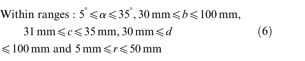
In the preliminary study, the fractional factorial design was used to select the main effect factor for each evaluation index. It was found that the most important effect for the Fmax, σ, w and q/t are b, b, c and r, respectively. However, due to the complex effects of the five parameters on the four evaluation indexes, the LHS was introduced in this study to give a full consideration of all five structural parameters. LHS technique is a uniform experimental sampling method, which is widely used for experimental designs with multiple factors and levels. As an effective sample reduction technology, it is thus suitable for simulation experiments. In this article, five factors and 30 sets of input data were randomly sampled using LHS 22 and the simulation of the newly proposed bending process was executed by DEFORM-3D. The DOE boundary conditions are discussed in section “Selection of design variables” and listed as follows: 5° ≤ α ≤ 35°, 30 mm ≤ b ≤ 100 mm, 31 mm ≤ c ≤ 35 mm, 30 mm ≤ d ≤ 100 mm and 5 mm ≤ r ≤ 50 mm. After calculation, the corresponding values such as Fmax, σ, w and q/t were achieved. Table 5 shows the results of all experimental schemes.
The results of simulation experiments.
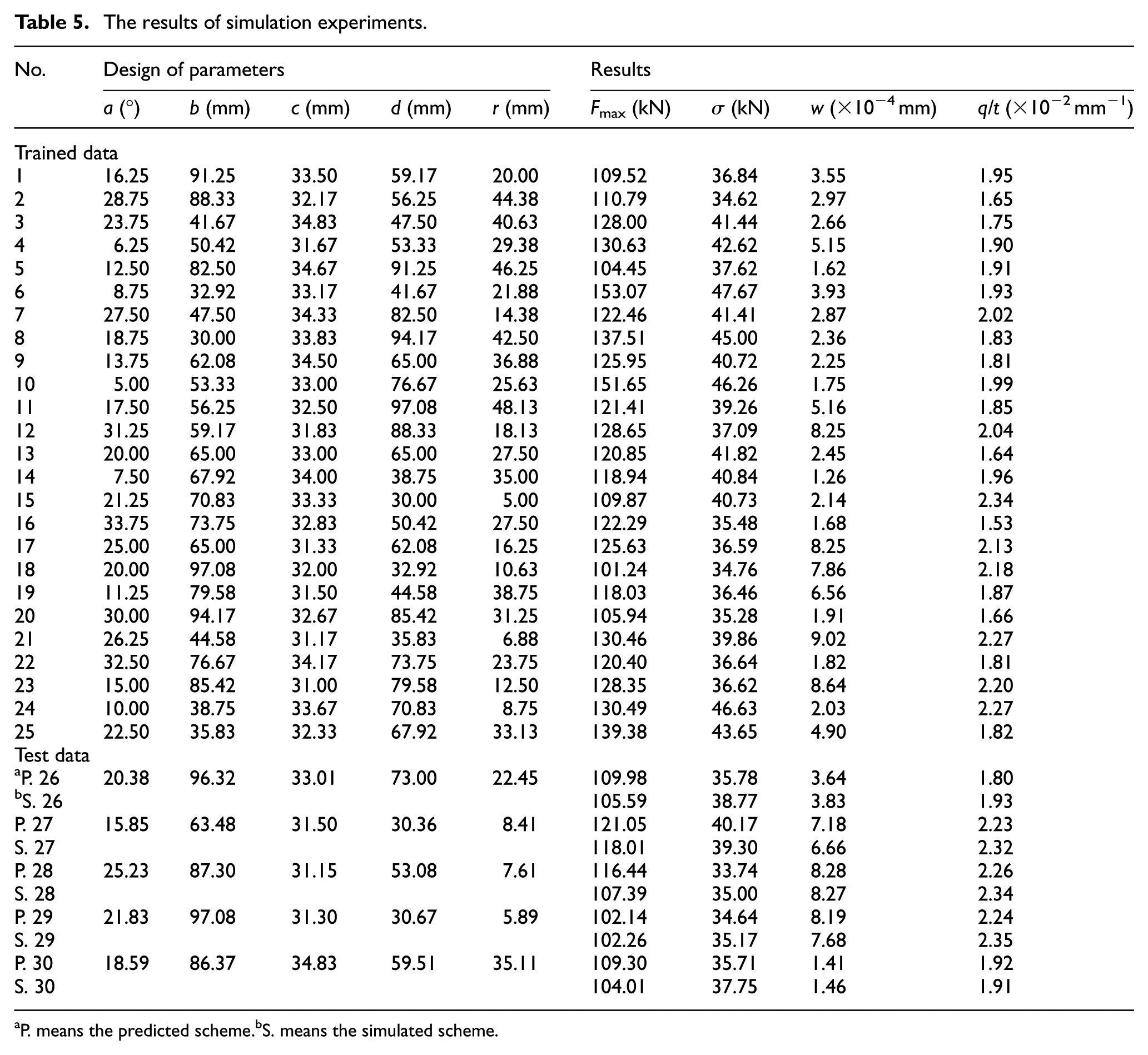
P. means the predicted scheme.bS. means the simulated scheme.
Establishing the Kriging metamodel
The Kriging model is an interpolation technology which can estimate experimental results by taking only a few related samples. Based on Table 5, nos 1–25 experimental sets were selected for establishing Kriging model using Dace toolbox of MATLAB software. For the Kriging model in this work, the local departures adopted the Gaussian correlation function and the parameters such as the θ value, the range and the mean squared error (MSE) were set as default by MATLAB. Furthermore, to test the accuracy of the established surrogate model, another five experimental sets, nos 26–30, were generated randomly within the ranges of design variables, and the simulation results are shown in Table 5. According to the calculation, it is clear that the average errors for Fmax, σ, w and q/t are 4.35%, 4.02%, 4.49% and 4.26%, respectively. The average errors between simulation and predicted values are all less than 5%, which verifies the precision of the established metamodel.
Execution of GA
GA is an adaptive random search algorithm which has advantages of concurrency and global convergence. In this study, parameters adopted in GA were set as follows. The mutation and crossover rate were set to 0.01 and 0.9. Uniform crossover was adopted, so that the parent chromosomes could contribute the gene level rather than the segment level. A total of 100 initial individuals were generated randomly within their ranges and the termination generations were set to 200. The optimization problem can be illustrated by the following equations


Generally, in engineering problems, it is difficult to achieve an optimal design point that can make all the objectives simultaneously be the best due to the complex relationship between input parameters and evaluation indexes. Therefore, an integrated goal IG was defined as equation (7) to assess the overall effects of structural parameters on the four optimization objectives

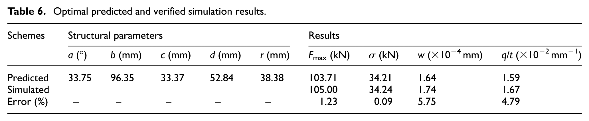
where w1, w2, w3 and w4 indicate weighting value of Fmax, σ, w and q/t. In this study, w1, w2, w3 and w4 were assigned the value of 0.3, 0.2, 0.2 and 0.3, respectively. The optimal die structural parameters were achieved by GA calculation, where a = 33.75°, b = 96.35 mm, c = 33.37 mm, d = 52.84 mm and r = 38.38 mm. According to the established Kriging surrogate model, the predicted values of Fmax, σ, w and q/t were 103.71 kN, 34.21 kN, 1.64 × 10⁻⁴ mm and 1.59 × 10⁻² mm−1, respectively. The verification experiments were carried out using the optimal die design parameters by DEFORM-3D software. As shown in Table 6, the errors between predicted and simulated results are 1.23%, 0.09%, 5.75% and 4.79%, respectively, which verifies the accuracy of the established Kriging metamodel.
Optimal predicted and verified simulation results.
Comparison between conventional and optimal die designs
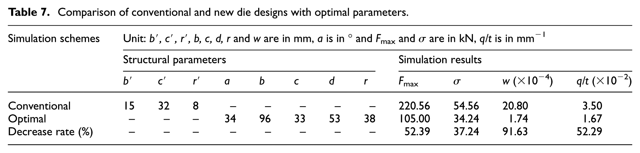
Figure 7 and Table 7 illustrate the comparison of evaluation results between conventional (indicated in black in Figure 7) and new optimal (highlighted in red) die designs. It is obvious that the bending quality and die service condition are significantly improved with the decrease in the maximum bending force, the extent of bending load non-uniformity, the maximum wear depth in lower rollers and the ratio value of the maximum damage to the responding minimum thickness in the local thinning area. And, the decrease percentages of Fmax, σ, w and q/t are about 52.39%, 37.24%, 91.63% and 52.29%, respectively.
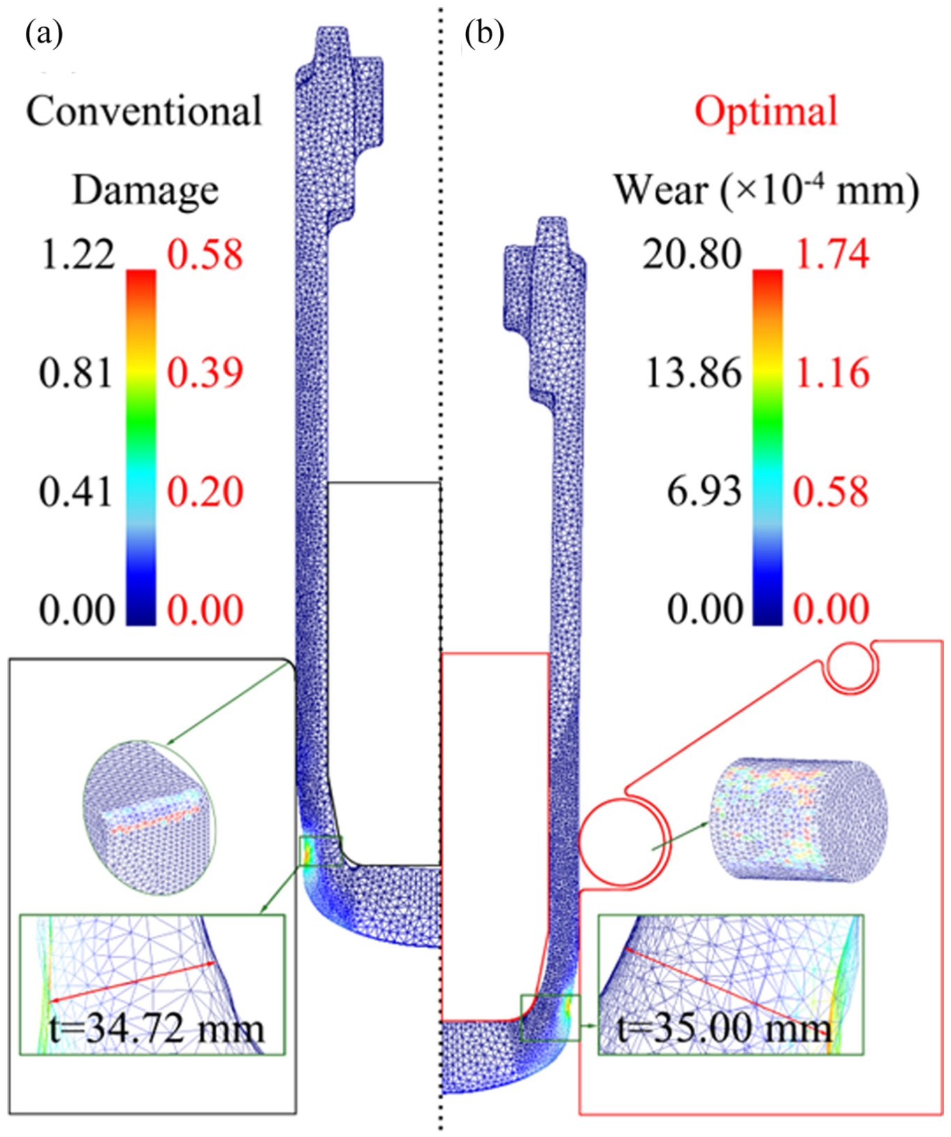
The comparison of optimization objectives in (a) conventional and (b) optimal dies.
Comparison of conventional and new die designs with optimal parameters.
Furthermore, a 500 ton press was employed to perform the bending operation and the trial product produced by the new optimal die design is displayed in Figure 8. The bending defects which appeared in the conventional bending process were not observed during the trial production. According to workshop records, 117 bending parts have been manufactured with the new die design in Dajiang Forging Ltd. and there are no early failures such as crack, fracture or local thinning occurred, which reveals the improvement of the new process design in failure control.
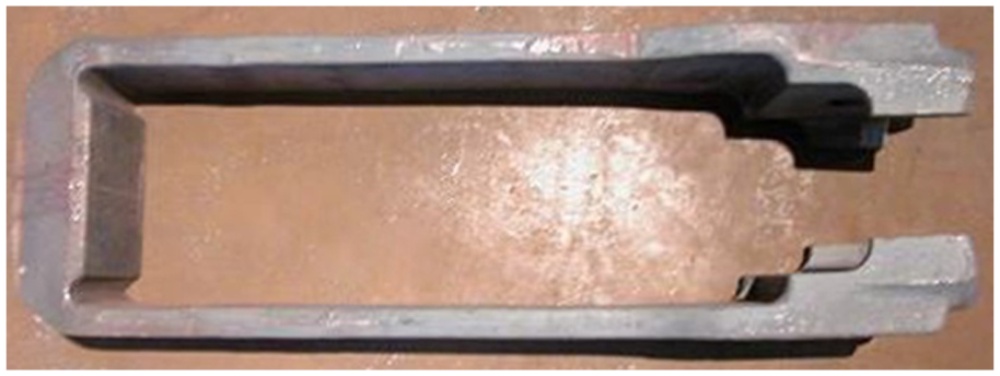
The trial product produced by the new optimal bending die.
Conclusion
A novel multi-stage bending process is proposed. The friction coefficient is significantly decreased using rollers taking the place of inlet fillets. By slightly increasing the clearance between the punch and die, the local thinning and excessive load are prevented. And, the maximum bending force and the extent of the bending load non-uniformity are decreased remarkably by introducing a slanting angle to the initial horizontal working surface.
The mechanism of the new multi-stage bending method is a V-shaped prebending followed by a U-shaped final bending. According to the contact patterns, the bending processing can be divided into three relatively steady stages and thus the bending quality has substantially improved.
Based on the Kriging surrogate model and GA optimization, the new optimal bending die design and the optimized objectives of Fmax, σ, w and q/t are achieved. Compared with the initial bending, the objective values are significantly decreased by 52.39%, 37.24%, 91.63% and 52.29%, respectively.
The bending quality is greatly improved, and the service life of bending die is effectively prolonged. In summary, the newly proposed multi-stage bending method is a feasible technique and may offer many advantages in the bending process of conventional large-scale forging with general presses. The microstructure evolution under the novel multi-stage bending mode and the corresponding changes in mechanical properties should be an interesting research topic, which deserves further and deeper investigation.
Footnotes
Acknowledgements
The authors would like to thank the Dajiang-Jiexin Forging participants to the project (in particular Mr J Zhou) for their cooperation.
Declaration of conflicting interests
The author(s) declared no potential conflicts of interest with respect to the research, authorship and/or publication of this article.
Funding
The author(s) disclosed receipt of the following financial support for the research, authorship and/or publication of this article: This work was financially supported by National Natural Science Foundation of China (51605392) and Fundamental Research Funds for the Central Universities of Southwest University (XDJK2017 D007).