
Abstract
The workpiece contour errors from previous process affect current process. In order to improve workpiece allowance distribution, this article presents a workpiece registration and localization adjustment method with contact inspection. According to the analysis of machining deviation, the rotational and translational registration matrixes from multi-tolerance surfaces to workpiece are obtained by surface characteristic and translational vectors. The workpiece localization (position and orientation) adjustment can be realized by transforming coordinate systems of 5-axis machine tool. Through adaptive and iterative registration and adjustment, the optimized workpiece localization for current process is obtained. The experimental results show that the method can improve allowance uniformity effectively.
Keywords
Introduction
Precise machining usually involves a series of processes. There may exist workpiece location error, distortion error, machine tool geometric error and other machining errors in previous process. These factors may lead to overcut or undercut (non-uniform allowance distribution) of some surfaces in current process, even if the shape of the workpiece meets the design requirements. This will result in the machining quality of the current process being seriously affected. In order to improve machining quality, many scholars put forward different methods from various fields. For example, Wang and Guo 1 proposed geometric error identification algorithm of numerical control (NC) machine tool using a laser tracker, and Davis et al. 2 presented an approach to control both the contour error and force using an adaptive robust controller. With the development of inspection technologies and instruments, on-machine probing system, contact scanning system, non-touch three-dimensional (3D) scanning system, coordinate measuring machine (CMM) and coordinate measuring arm (CMR) can be applied to inspect workpiece contour deviation between processes, and some other effective methods can be researched.
After inspection, how to improve allowance uniformity for this process is put forward. Some efforts have been made concerning workpiece localization algorithms. The solutions include adjusting workpiece localization, relocating workpiece by adaptive fixture, regenerating NC program, and so on. With the development of machine tool and NC control technology, the swivel, frames and inclined plane machining functions of 5-axis machine tool can be used to control rotary axes and angle the tool (transform workpiece coordinate system (WCS)).3,4 Comparing with other methods, workpiece localization adjustment can be realized easily by workpiece registration and WCS transformation.
The registration requires two inputs: theoretical and actual inspection data. There are different registration algorithms for non-contact (optical) and contact inspection. For non-contact inspection, the most widely used point set registration (PSR) algorithm is the iterative closest point (ICP) algorithm introduced by Besl. 5 In recent years, some scholars have developed improved ICP algorithm and applied them to point cloud registration.6,7 Ge and Thomas 8 proposed the nonlinear Gauss–Helmert least square (GH-LS) approach for 3D point cloud. Ma et al. 9 proposed an efficient rotation estimation algorithm for point clouds of structured scenes. Zhu et al. 10 presented a unified frame work for best-fitting of a complex rigid surface, and Sun et al. 11 developed a unified localization technique for sculptured surface. Tang et al. 12 presented a locating error analysis approach for workpiece with general fixture layouts and parameterized tolerances. Srinivasan et al. 13 developed automatic part localization in a computer numerical control (CNC) machine coordinate system by means of 3D scans. Kong et al. 14 completed theoretical and experimental evaluation of surface quality for optical free-form surfaces by free-form surface-matching algorithm. The registrations can satisfy single tolerance constraint for some specific surfaces. However, when the tolerance constraints are different, the PSR algorithm may lead to conflicting result. 15 These lead the PSR algorithms only to work with roughly pre-registered surfaces.16–19
For contact inspection, some researchers modeled the registration as a constrained least-squares optimization problem. An optimization model for symmetric workpiece was developed by Zhang et al. 15 Yan et al. 20 applied genetic algorithms (GAs) to solve the problem of stock surface registration. Wang et al. 21 improved the allowance distribution of blade by multivariate statistical process control. Mehrad et al. 22 realized the matching between point sets and design model through rough and fine localizations, which is based on similarities in curvatures and distances. A combination of the alternating optimization and successive linearization methods was proposed by Dai et al. 23 However, the constrained optimization is difficult to solve in view of the numerical stability, efficiency and accuracy. 19
Comparing with non-contact inspection, contact inspection data have more relationship information: theoretical and actual measured point pairs with definite detection directions, point sets, tolerances and corresponding surfaces. However, due to the influence of probe size and surface curvature, maybe there is no direct spatial relationship between the point pairs. The registration cannot directly be established by the measured points. Chatelain and Fortin 24 formulated the registration as a min–max problem, which means the constraint values are hard to appropriately assign.
In this article, based on the workpiece contact inspection data, an adaptive and iterative registration and localization adjustment method based on the rotational, translational registration matrixes and topology of machine tool is proposed. It can improve workpiece allowance uniformity that has multi-tolerance constraints surfaces.
The rest of the article is organized as follows. In section “The registration theory,” the registration theory of the proposed method is introduced. The calculation of rotational and translational registration matrixes from surface to workpiece is described in sections “The calculation of rotational registration matrix” and “The calculation of translational registration matrix.” How to realize the transformation of WCS for 5-axis machine tool is described in section “The calculation of WCS transformation parameters.” In section “Adaptive iterative workpiece localization adjustment process,” the adaptive and iterative adjustment process is given. To verify the validity, some experiment results are presented in section “Experiment.” Finally, some conclusions are drawn.
The registration theory
According to different surface machining tolerances and curvature continuities, the workpiece contour profile can be divided into cylindrical surface, plane and free-form surface in this article. For each surface, the over tolerance (OT) can be analyzed from the contact inspection data accurately and independently (Figure 1).
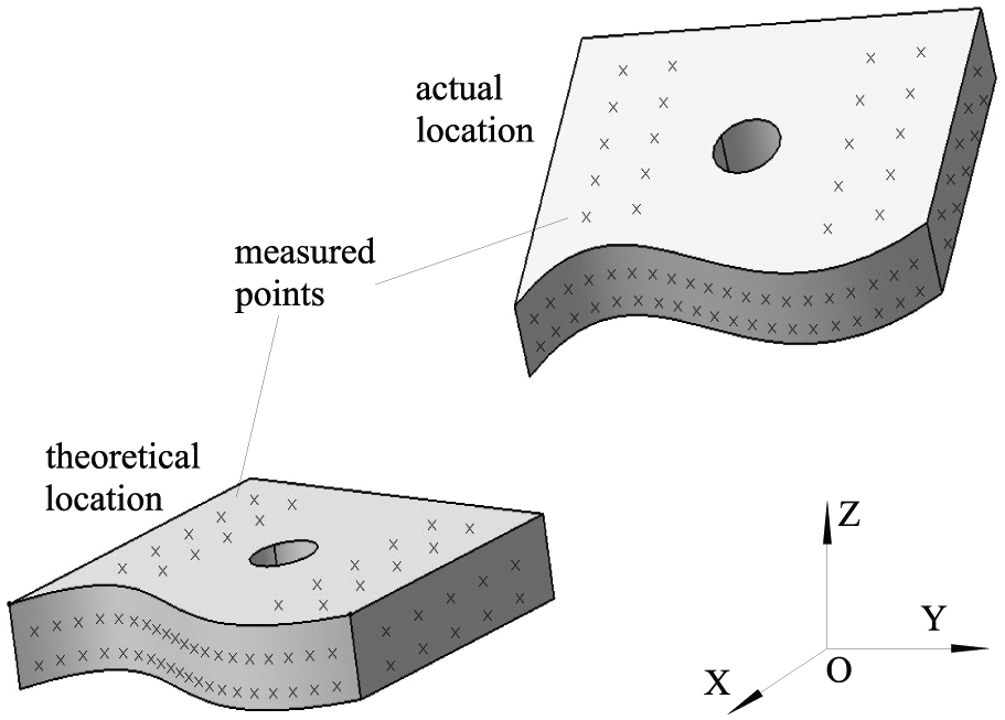
Relationship between the workpiece actual location and theoretical location.
Set WCS as the inspection coordinate system (ICS). Denote the theoretical mth measured point on the nth surface as Pn_m(xn_m, yn_m, zn_m), the actual point as P′n_m(x′n_m, y′n_m, z′n_m), where Pn_m and P′n_m are a pair of points, the detection direction as
If OT of any measured point is not 0, then it illustrates that the contour deviation was caused in the previous machining process.
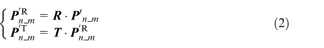
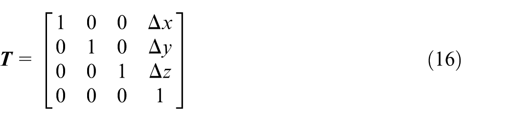
In order to simplify the registration, the homogeneous coordinates and transformation matrix (HTM) are used. The translation can be represented by HTM
where
The calculation of rotational registration matrix
The workpiece registration matrix is integrated from each surface. However, there is no unified registration algorithm for the different surface characteristic vector definition.
The surface characteristic vector
The characteristic vector represents surface orientation. In this article, the normal vector of plane, the axial vector of cylindrical surface and the integrated vector of free-form surface are defined.
1. The normal vector of plane
Define the nth theoretical plane equation as
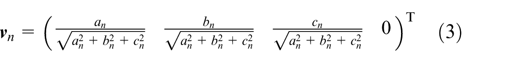
Substitute arbitrary three points into plane equation, an, bn and cn can be obtained.
For the nth actual plane, define the fitting plane equation according to the least-squares method, and the unit normal vector
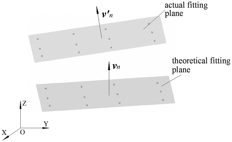
The normal vector and measured points of plane.
2. The axial vector of cylindrical surface
Define the unit axial vector of the nth theoretical cylindrical surface as
Then
In order to guarantee precision, the measured points should be distributed over the cylindrical surface (Figure 3).
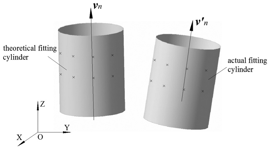
The axial vector and measured points of cylindrical surface.
3. The integrated vector of free-form surface
As shown in Figure 4, the vector
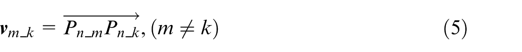
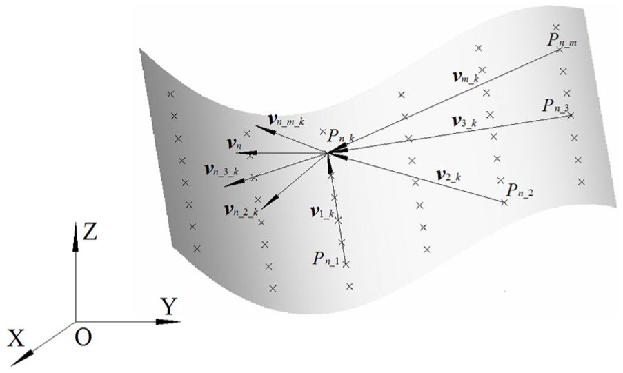
The integrated vector and measured points of free-form surface.
Then, the normal vector

The integrated unit vector
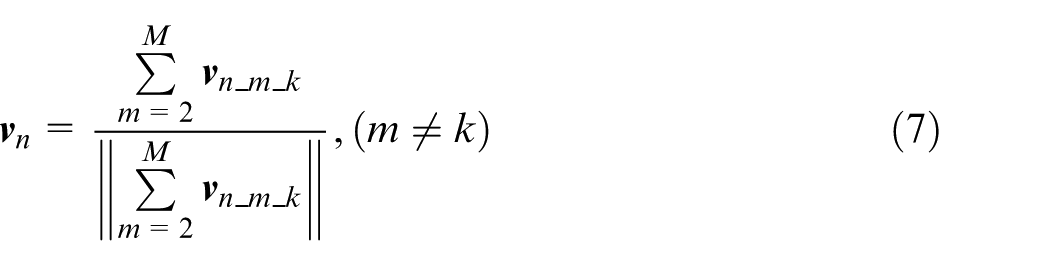
According to the same method and corresponding point pairs, the integrated vector
The surface rotational registration matrix
Define


The nth surface rotational registration matrix
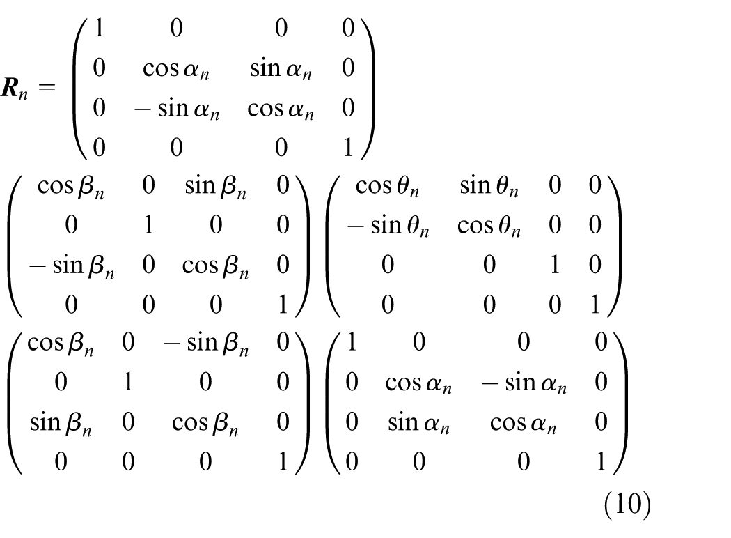
where
The rotation from actual characteristic vector to theoretical one.
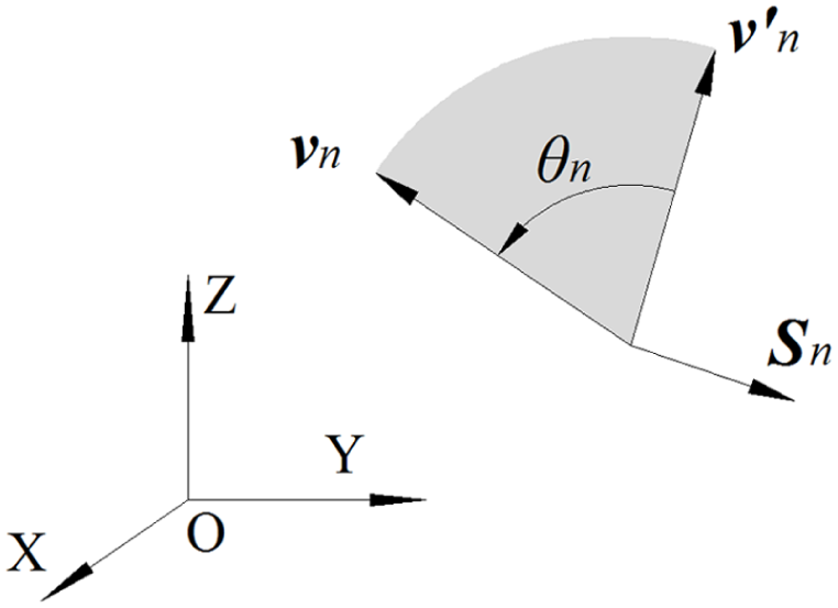
The workpiece rotational registration matrix
After obtaining

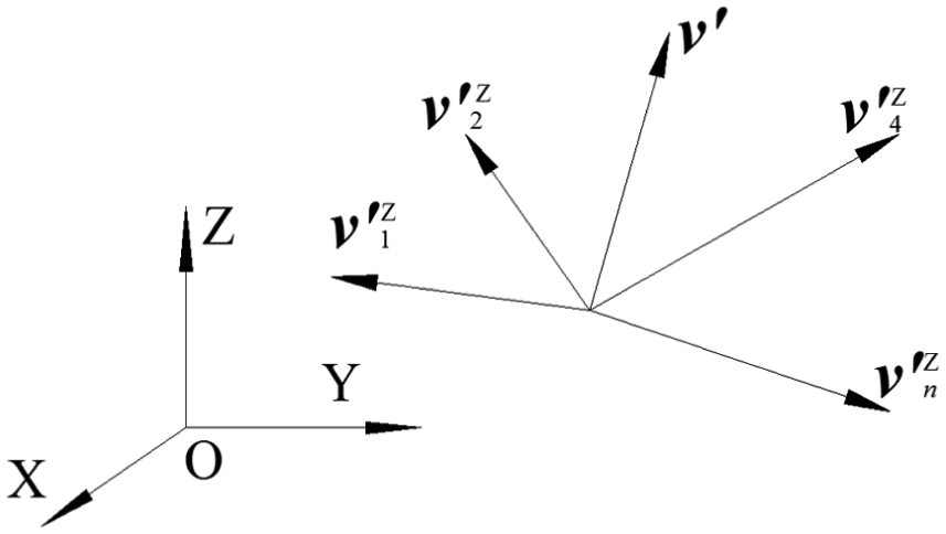
The actual transformed vectors based on Z axis vector.
Define the workpiece actual characteristic unit vector as
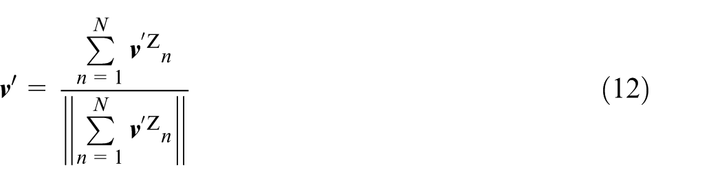
where N is the amount of inspection surfaces.
Through the transformation of actual characteristic vector, the workpiece theoretical characteristic vector is defined as Z axis vector. According to the similar algorithm, the matrix
According to the principle of registration theory, the coordinates of actual measured points
The calculation of translational registration matrix
After workpiece rotational registration, the coordinates of the actual measured points have been fine-tuned, and the parallelism of actual and theoretical direction of each measured surface has been improved. However, because the rotational registration is around the origin of WCS, it may deviate the workpiece from the theoretical position.
The surface translational registration vector
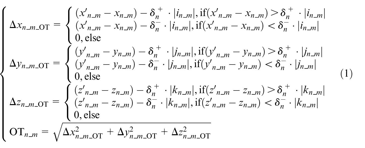
Before translational registration, it needs to caculate the OT of measured points by equation (1) after rotational registration according to the surface machining tolerances again. If OT of any measured point is not 0, the workpiece translational registration is necessary, and vice versa.
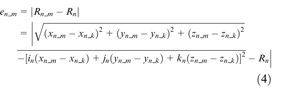
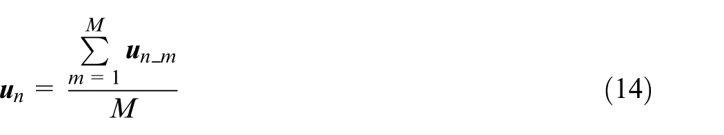
According to multi-tolerance conditions of different surfaces, the OT of an actual measured point
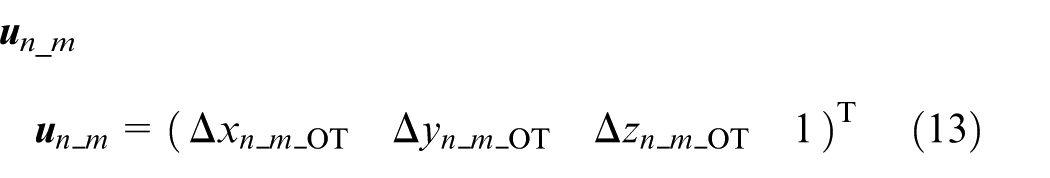
In order to satisfy the translational registration of nth surface, the surface translation vector
The workpiece translational registration matrix
In order to satisfy the workpiece translational requirement, the workpiece translation vector

where Δx, Δy and Δz are the workpiece registration distances in X, Y and Z directions, respectively. Then the workpiece translational registration matrix
The calculation of WCS transformation parameters
With swivel, frame or inclined plane machining functions of 5-axis machine tool, starting from the initial WCS, the localization of WCS for registration is defined by some specific feed axis movement parameters.1,3 They can be calculated by the registration matrixes and topology of machine tool.
The frame translation can be realized by the movement SX, SY and SZ of X, Y and Z axes. In addition, the orientation can be defined by the rotation of rotary axes. Taking 5-axis machine tool of XFYZBA topology (which has two rotary axes in the head) as an example, the orientation can be defined by the rotation SA and SB of A and B axes.
Taking the worktable as reference, the frame origin point and orientation can be described by integrated geometric model of 5-axis machine tools, registration matrix
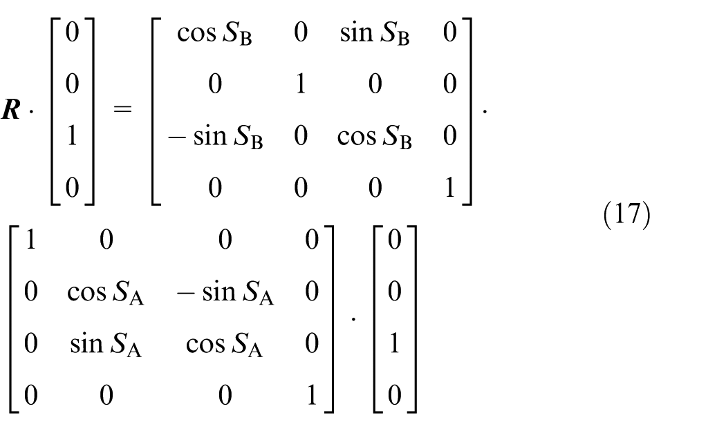
where (0, 0, LAB) are the A axis origin coordinates in the B axis coordinates system, (LX, LY, LZ) are the cutter location point coordinates in the A axis coordinates system.
So the WCS transformation parameters can be calculated by solving the equations (17) and (18).
Adaptive iterative workpiece localization adjustment process
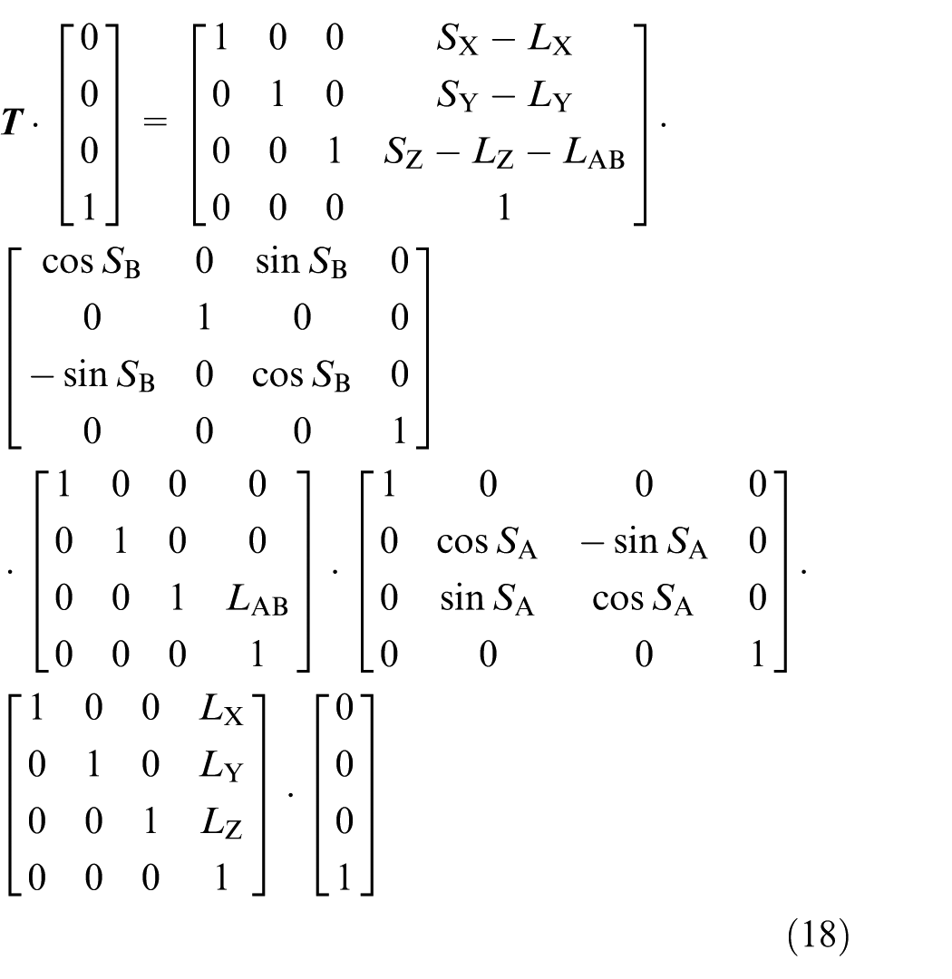
The workpiece may not fully meet the optimal location only by single adjustment. This article puts forward an adaptive and iterative workpiece localization adjustment process (Figure 7). The steps are as follows:
Set WCS as ICS and inspect the workpiece according to the contact inspection specification.
Calculate the machining deviation by inspection data and multi-tolerance conditions.
Determine whether any measured point is out of tolerance or the amount of deviated points is decreasing or not, if it is true go to step (4), else end the process.
Calculate the registration matrix and WCS transformation parameters, then go to step (1).
The flow chart of proposed workpiece localization process.
Experiment
Because the accuracy of aviation structural part is susceptible to the machining process complexity and error factors, the need for machining localization adjustment is more urgent. As representative of typical aviation structure part, an S shape test piece from ISO test conditions for machining centers was used to verify the proposed method. 28 It includes one plane, two cylindrical holes and two ruled surfaces, whose machining tolerances are ±0.05, ±0.25 and ±0.1 mm, respectively, and the WCS is defined by reference planes A, B and C, as shown in Figure 8. The amounts of measured points in each surface are 5, 10 and 22.
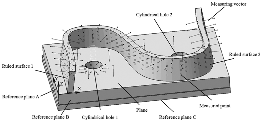
S shape test piece.
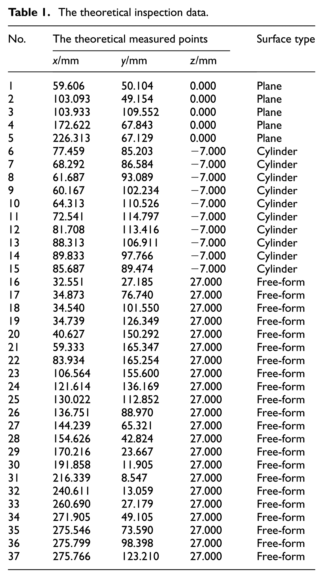
To verify the effectiveness of the proposed method, a series of milling experiments were conducted on a PARPAS BF-100TTM 5-axis machine tool of which kinetic structure is XFYZBA (machine structure parameters LAB, LX, LY, LZ are 0, 0, 0, –516.221, respectively), as shown in Figure 9. The theoretical inspection data are shown in Table 1. The actual initial measured point distributions are shown in Figure 10. The OT exists in each measured point.
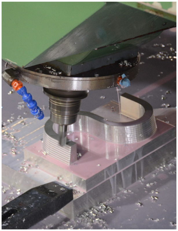
The scene of machining an S shape test piece.
The theoretical inspection data.
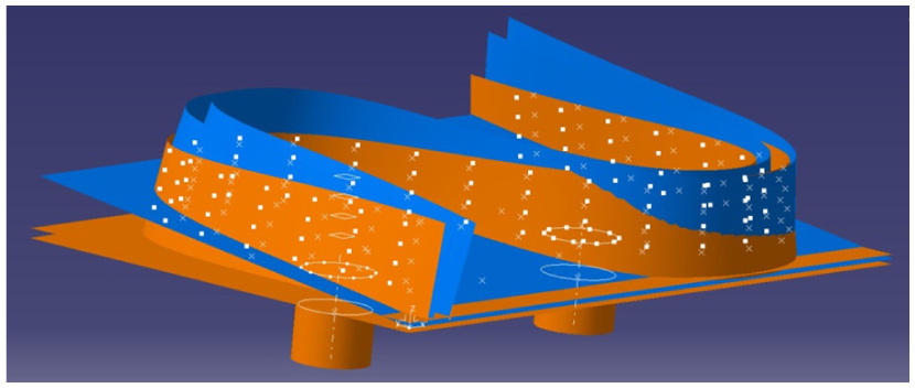
The actual initial measured points distribution.
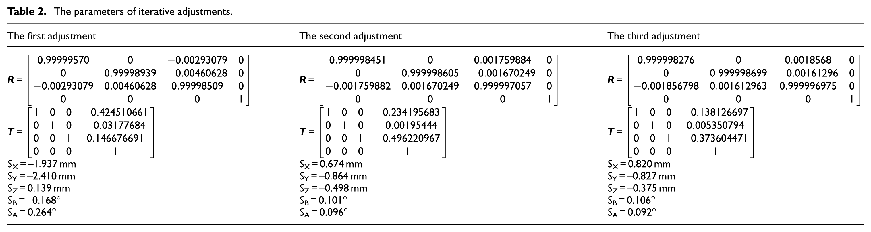
With the proposed registration and adjustment method, the average OT is gradually decreased from 1.510 to 0.816 mm (after the first adjustment), to 0.304 mm (after the second adjustment) and to 0 (after the third adjustment). Finally, none of the measured points is undercut or overcut. The machining precision of current process and allowance uniformity are guaranteed. The parameters of iterative adjustments are shown in Table 2 and Figure 11, and Figure 12 shows the OT after each adjustment.
The parameters of iterative adjustments.
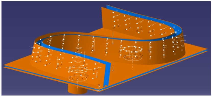
The actual measured points distribution after registration and adjustment.
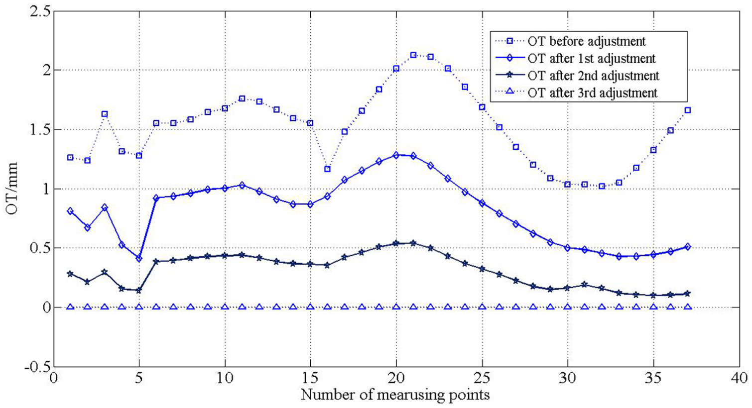
The OT after each adjustment.
Conclusion
In order to solve the problem about non-uniform allowance distribution in precise machining process, an adaptive iterative workpiece registration and localization adjustment method with contact inspection data is proposed. The method applies the contact inspection data to calculate rotational and translational registration matrices from surfaces under multi-tolerance conditions to workpiece. The localization can be realized by WCS transformation of which the parameters are calculated by the registration results and the topology of 5-axis machine tool. In order to improve the localization accuracy, an adaptive iterative adjustment process is given. Through a series of experiments, the results show that the proposed method can optimize workpiece localization and improve allowance uniformity effectively.
Footnotes
Appendix 1
Declaration of conflicting interests
The author(s) declared no potential conflicts of interest with respect to the research, authorship, and/or publication of this article.
Funding
The author(s) disclosed receipt of the following financial support for the research, authorship, and/or publication of this article: This work is supported by the Special Fund of High-end CNC Machine Tools and Basic Manufacturing Equipment (2015ZX04001002), China.