
Abstract
Reverse engineering is when a real part is analysed in detail in order to create a numerical or virtual model. Reverse engineering allows for multiple redesign possibilities, including changes in the material, the shape and the parameters of the part. Reverse engineering is mostly a manual activity for companies and is thus time consuming. Indeed, measurements must be done in scanned files in order to fit sketches on a mesh and to finally rebuild the computer-aided design/bill of material. This manual process is acceptable when reverse engineering is exceptional. But it is considered as a non-value task when reverse engineering is routine. This non-value task could be automated, at least partially. To make it possible, a capitalization of the company’s part catalogue is a necessary step to proceed. The use of this capitalization can then drive the reverse engineering tasks to enable faster redesign possibilities. The aim of this contribution is thus to propose a knowledge model to support reverse engineering activities in order to integrate the reversed parts quickly into the new product’s detailed design. An extended knowledge framework based on the core product model is proposed, and a use case is shown to validate the feasibility of the proposal of the reverse engineering methodology called PHENIX.
Introduction
Reverse engineering (RE) is an activity which consists of digitising a real part in order to create a numerical or virtual model of it.1,2 A number of domains are motivated to apply utilising RE, such as virtual prototyping, 2 metrology, product lifecycle extension, visual arts, museology, industrial conservation and competitive analysis. For example, in the industrial context, RE can be used at different steps of a product’s lifecycle, especially in the followings cases: (a) when the original design is not supported by sufficient or existing technical documents; (b) if the original supplier has disappeared or no longer manufactures the part; and (c) if the original part is damaged or broken and neither plans nor drawings are available. RE is most useful for legacy parts without computer-aided design (CAD) model representations.
From the scientific literature, RE is capable of converting a point cloud from digitising phases into an ‘accurate’ model, minimising the intervention of the user. 3 The automatic steps of the RE process are mainly focused on geometrical recognition. The geometry obtained is usually static (i.e. a set of triangles, free form surfaces, or geometrical features in a manifold static model) and barely reusable.
In this article, RE is considered as an activity whose objective is to obtain a parametric three-dimensional (3D) model from a part and hence to allow for redesigning possibilities, including changes in the material, the shape and the parameters of that part. RE is a manual, time-consuming activity for companies. Measurements must be deduced by scanning files and then fitting sketches onto mesh in order to deduce the CAD/bill of material (BOM), including both original and new requirements. This manual process is acceptable when RE is exceptional, but considered as a non-value task (a waste of time) when RE is routine. RE activity could be partially automated in order to reduce the modelling process time. The capitalization of a company’s part catalogue is the best way to proceed. Using this capitalization drives the RE tasks and enables more redesign possibilities as well as their more rapid realisation.
The aim of this contribution is split into two aspects: (a) to propose a knowledge model to support RE activity in order to quickly integrate RE parts in the detail design activity (see Figure 1) and (b) to propose a new RE methodology reusing existing features to produce multi-CAD representations.
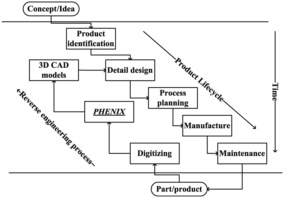
Positioning of the PHENIX solution in a product’s lifecycle.
The Product History–based reverse ENgineering: towards an Integrated eXpert approach (PHENIX) – no.ANR-08-COSI-011 project was created to elaborate this knowledge model. The rich CAD parameters obtained by PHENIX are a result of this knowledge; their use now makes redesign possible.
The core product model (CPM) from the National Institute of Standards and Technology (NIST) is utilised and extended to model the knowledge used to support this RE process.
The article is organised as follows. A literature survey about RE processes is presented next, followed by an explanation and discussion of the positioning of the PHENIX approach. The knowledge-based framework for RE is then proposed, and the CPM extension is presented in detail. This work ends with an implementation of the proposed knowledge framework in a demonstrator called PHENIX system on an industrial case.
Literature survey
The RE process
Among the set of current approaches, one is to improve the RE process by reducing user interactions in order to decrease the time needed to complete the process. 3 A full, accurate and automatic recognition of a 3D point cloud is still a central problem in RE. Recent efficient Information Technology (IT) systems such as GeomagicTM propose powerful algorithms to complete the RE operation. However, such software tools still require a high-level interaction with the user, including a large amount of inputs. RE software approaches are mainly focused on the segmentation and feature recognition functions. The segmentation of a meshed 3D point cloud consists of dividing the 3D point cloud of a given object into a set of n point clouds representing the n features that compose the object.
Three segmentation techniques are commonly used.4,5 First, the region-based technique utilises spatial coherence to organise the mesh into meaningful groups. The best techniques are based on region-group approximation and allow the recognition of simple forms such as planes and cylinders, and spherical and conical surfaces. Second, the edge-based technique isolates any discontinuities in the 3D point cloud. Break areas, such as steps, and discontinuities of normal and curvature orientations are recognised. The third type of technique is a hybrid approach that combines region and edge detection. 6 All of these techniques lead to surface detection of non-uniform rational basis splines (NURBS), but not to the extraction of parametric solid shapes.
Feature recognition7,8 is usually defined as the ability to automatically or interactively identify and group topological entities from a solid model. A feature has a functional meaning, indicating forms such as cylindrical holes, slots, pockets and fillets. Feature recognition methods search the boundary of a solid according to a pattern of faces and edges (i.e. extracting features and their parameters from the point cloud). Feature recognition is very advantageous because it allows solid modelling, which improves the quality of the rebuilt CAD model and offers redesign possibilities.
For example, one of the most famous applications is ‘Reverse Engineering FeAture Based’ (REFAB), 9 a geometric feature-based RE system. REFAB interactively creates the CAD model of a part with a significant number of specialised manufacturing features such as holes and pockets. This IT development allows the user to fit features such as cylinders and planes onto a point cloud. The segmentation, the fitting and the constraints are performed from the point cloud, and the features are used as references. In the same way, Sunil and Pande 10 extract the sheet metal features in a point cloud, and Urbanic et al. 11 extract milling features. Xu et al. 12 extract STEP-NC features from meshes. Their library of features consists of a set of specific manufacturing process, and their feature recognition from scripts is performed on a point cloud.
These related works are sufficient to enable redesign in a specific manufacturing process case, but not for any other expertise fields such as design and functional analysis.
Another approach in the survey is to improve the RE process itself. The major idea is to suggest engineering methods in order to extract original design intents.
The Virtual Parts Engineering Research Initiative project (VPERI) 13 was created by the US Army Research Office to provide the vision, strategy and engineering software to help solve RE problems. VPERI project experts explain that knowledge about the geometric shape and size is necessary but not sufficient to reproduce the part. Re-engineering and redesign need functional specifications. A design interface is used to allow the addition of knowledge in the form of algebraic equations. These represent the engineering knowledge of the component according to its functional specification, the physical laws that govern its behaviour, any spatial arrangements and so on. This interface provides mechanisms that allow designers to ensure that the functional requirements are fulfilled and helps designers to explore alternatives by assisting them in making changes. Knowledge arises from the analysis and is simply expressed and transcribed into variables that are interpreted by the VPERI software. In the same way, the Multiple Engineering Resources aGent Environment (MERGE) system developed by Musuvathy et al. 14 is a collaborative platform.
Bernard et al. 15 propose an approach for the redesign of old mechanisms and try to answer the question of ‘how to make the life of technical information of collections, archives and heritage sites longer?’. In this approach, the authors assume that knowledge has to be capitalised from the functional block diagram of the functional analysis method (APTETM). Two types of knowledge are distinguished: functional and mechanical characteristics (internal flow design only: functional and structural) and the external data (socio-technical context environment, etc.). In the mechanical engineering domain, as an assumption, only the first type of knowledge is considered. In a classical and direct design operation, a CAD model contains expert knowledge provided by the designer (i.e. parameters, relations and attributes). This knowledge is domain related and concerns, for instance, a product’s mechanical functions or its manufacturing process. In an RE context, several details of the product are known. These details enable to assume the ‘product history’ and to consider it in the reverse process.
According to the state of the art, the usual RE process could be divided into the following steps: (a) digitising, filtering and extracting the 3D mesh of a mechanical part; (b) the segmentation process required to detect geometric entities; and (c) determining a set of geometric operations such as feature recognition. Several works such as VPERI improve this usual process by adding engineering-based methods (annotations of point cloud and drawings on interactive solutions) (see Figure 2).
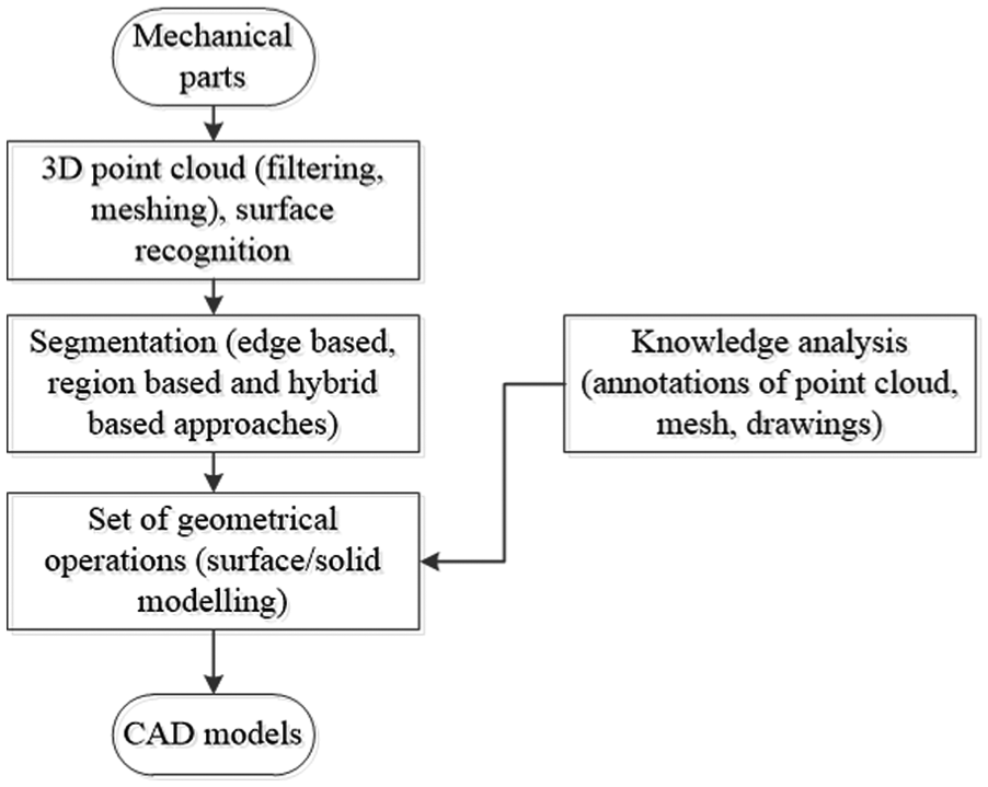
Usual RE process.
All of these references provide solutions of RE, but do not provide the ability to reuse knowledge semi-automatically.
The objective of the PHENIX project is to build a parametric CAD model from a point cloud in a recurrent context. It appears that two approaches from the state of the art could be reused and adapted to the PHENIX context. First, the feature-based technique shown in REFAB 9 brings answers to the recurrent context aspect. The features previously saved in a database can be fit into the point cloud. This feature-based technique is well adapted to support recurrent RE tasks. Second, the solutions based on improving RE itself are also interesting for this contribution. Indeed, the aim is to support parametric CAD modelling using a knowledge-based approach. 16 A knowledge framework helps the expert to structure his expert information during a capitalisation phase and to fit the existing features (resulting from capitalisation) during the reusing phase.
The PHENIX methodology has merged these two approaches to provide a knowledge-based RE framework and a semi-automatic fitting of known features into the point cloud. PHENIX is thus a new RE process which proposes to use knowledge as soon as possible in order to obtain automatic parametric CAD models (see Figure 3).
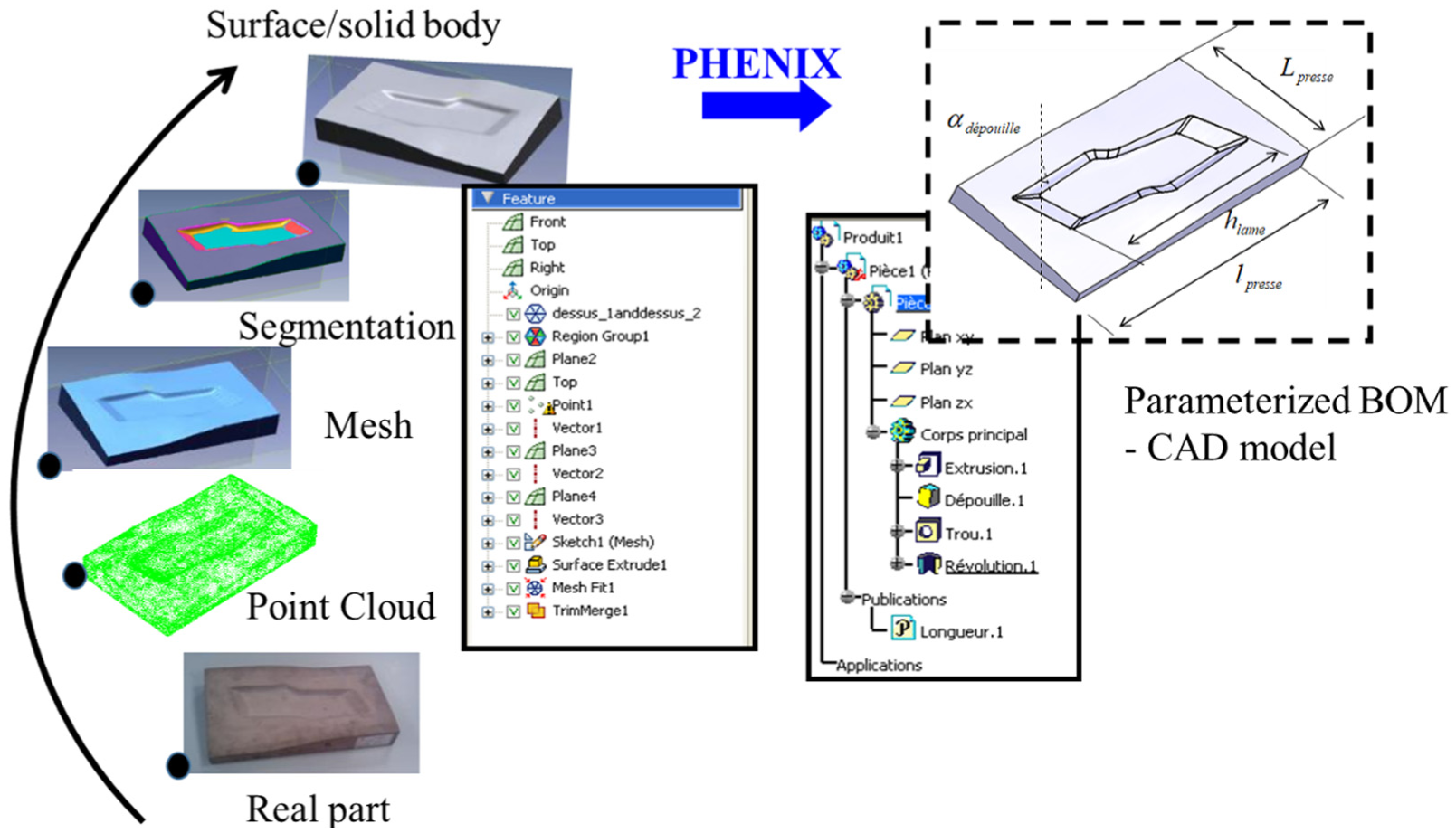
PHENIX approach compared to those in the literature.
Positioning of the PHENIX methodology in the literature survey
During the RE process, the original design intentions are assumed by the expert. The specific forms on the part are due to the original functional specifications or due to the original manufacturing process. Thus, not just one CAD but several parametric models could be obtained, depending on the modelling assumptions used by the expert when he or she constructs the CAD model. Several parametric CAD models can then coexist, and the relations between these models have to be maintained and managed.
This multi-representation implies thinking about how to manage the different models using a product data management (PDM) system for two reasons:
To structure and track the RE process;
To manage the links between the different generated CAD models (i.e. to manage engineering changes).
The PHENIX research methodology is based on
A feature-based knowledge database to drive the RE process;
A data model that supports the RE process and allows the management of the multiple resulting CAD representations.
The main concept of the PHENIX approach is to offer a ‘knowledge-based framework’ for RE. One way to achieve this is to use a product data model to support the knowledge base during the RE process. This approach implies exploring the state of the art about product modelling in order to identify the best product data models to support the RE process. The following subsection is dedicated to this point.
Product modelling
The identified works present a huge variety of product models.17,18 The function behaviour structure (FBS) summarises the three main classes of product knowledge as follows:
Functional description (function) or the possible functions that the product must ensure throughout its lifecycle;
Behaviour description (behaviour) or how the product has to work in order to ensure those functions;
Structural description (structure) which describes the physical representation of the product (geometrics, parameters, etc.).
The Methods and tools Oriented to Knowledge-based Acquisition model (MOKA) 19 was developed in the framework of the European Strategic Program on Research in Information Technology (ESPRIT) project. This model represents the product in five complementary views as follows:
Structure view is the main view to which the other views are attached;
Representation view, which is the geometrical description of the product;
Functional view, which groups together the function, the principle solution and the technical solution;
Behaviour view, which includes the behaviour, state and transition descriptions;
Technical view that describes the technologies, the manufacturing processes and the material used for the manufacturing of the product.
The Product, Process, Organisation model (PPO) 20 was proposed in the project ‘Integration, Product, Process, Organisation for the improvement engineering Performances’ (IPPOP). The objective of this project was to develop an open collaborative system to support and share information between actors throughout the whole lifecycle of a design project by the integration of views such as product, process and organisation. This model is mainly based on a view called ‘Modelled Entity’. Each bit of information on the product is considered as a modelling entity which could be a component, an interface, a function or a behaviour.
Although not really considered as a product model, the STandard for the Exchange of Product model data standard (STEP) is also considered.19,21 Indeed, Express-G modelling, mainly APs 203, 209 and 214, allows the mechanical/manufacturing, and electronic/electrical fields have to be taken into account.
The CPM, 22 proposed by the NIST inspired by STEP, is an easy-to-use product model that is extendible to represent the information linked to the management of a product’s lifecycle. The CPM is independent of any development process and enables the full engineering context to be captured. The CPM is based on the Unified Modelling Language (UML) to represent a large range of information used in a product lifecycle management (PLM) system.
The CPM can be extended for our specific purpose. Previous extensions already exist, such as the ‘Open Assembly Model’ (OAM) that enables the management of assemblies, parts, tolerances and so on. The OAM extension is used to distinguish features associated with parts or assemblies to specify different types of constraints (geometrical or positioning constraints) that can be different with respect to the system level.
CPM models can be grouped into four classes according to the types of knowledge they cover:
Abstract classes group generic objects, thereby allowing the classification of product information by inheritance relations. These are mainly the ‘CoreProductModel’ class, the ‘CommonCore Object’ class, split into ‘Core entity’ for the physical object and ‘CoreProperty’ for the properties, and the ‘CommonCoreRelationship’ class to describe the types of relations.
Object classes, which are instantiating classes in concrete models. They inherit from the ‘Common CoreObject’ class and its inheritance classes such as feature and form.
Relationship classes, which inherit from the ‘CoreRelationship’ class. These integrate relationships between a product’s objects.
Utility classes contain specific attributes such as complementary information and the objects’ properties.
The CPM provides a multi-view representation of the product through the notion of artefact. The class ‘artefact’ is the main class of the CPM model. It represents an entity in a product, which could be a component, a part, a sub-assembly or an assembly. All of these entities could be represented or connected by relations in the ‘artefact’ class (subArtefact/subArtefactOf). The ‘Feature’ class is a part of the physical shape of an artefact. The ‘specification’ class allows for a product description that is close to the customer and the engineering needs. A need (requirement need) is an element of an artefact specification which determines a specific aspect of the function or the geometry of the product.
The CPM model provides benefits for knowledge modelling dedicated to the RE context thanks to the following aspects:
The CPM is a generic model and is conceptually rich. It covers the overall product lifecycle and is not dedicated to any specific engineering expertise. It permits a multi-expertise representation of the product through the CPM and OAM models.
Its hierarchical and modular structure allows the extension and implementation of the model. This property is obtained by its information categorization according to the types of class and the inheritance relation which allow information to be dedicated gradually (with granularity) to an expertise domain.
The concepts in the CPM are consistent with the majority of the PLM/CAD systems used in the industry. This property allows to achieve interoperability capacities between the model (and its extensions) and other commercial software.
Synthesis: why choose the CPM extension?
The aim of the proposed data model is to support the RE process. This process requires integration between the CAD tools and the PDM systems. Therefore, this contribution focuses on using the CPM extended data model, especially because it allows to
Manage the different levels of modelling, ranging from the geometrical definition of parts to the data of their lifecycle (versions and multi-representations);
Extend the model for specific applications. This extension has to allow the data distribution which could be used for other applications (such as geometrical modelling, finite element method (FEM) and dimensioning);
Support in making parallel the multi-view RE process and data based on the knowledge base (i.e. to associate several multi-representations for the same object).
The CPM from the NIST has been chosen for this work. A specific extension has been developed in order to first, support the reverse process; and second, to manage the multi-representations in the knowledge database. This extension has been implemented and tested in this contribution.
Proposition: knowledge-based framework for RE
As stated earlier, the usual RE process can be divided into three steps. The first step consists of digitising, filtering and building the 3D mesh of a mechanical part. The second step is the segmentation process to detect geometric entities. The third step is a set of geometric operations such as feature recognition and fitting. The resulting rebuilt model is generally ‘static’ and is barely reusable. From this point of view, it is very difficult to obtain a rebuilt model that looks like a CAD model (i.e. a set of tree-structured manufacturing and functional features with constraints, parameters, rules and relationships).
The RE process manages three categories of data, as presented in Table 1.
Types of knowledge.
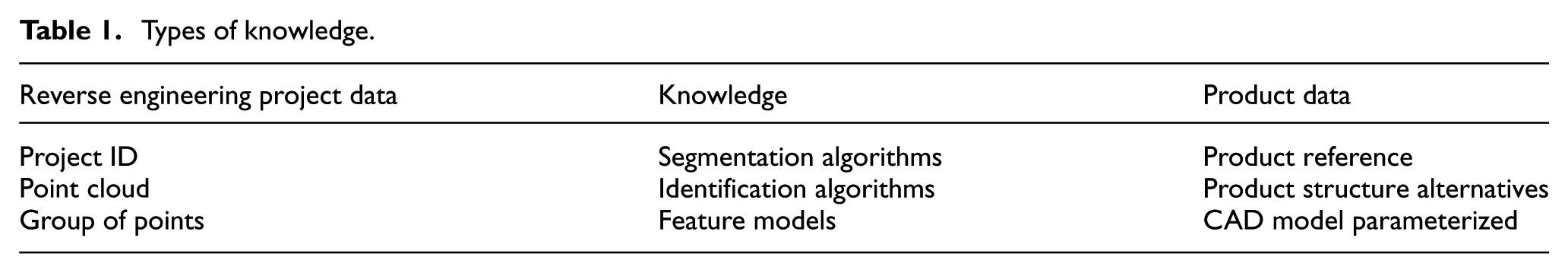
Descriptive data of the RE project, such as the ID, the results of the scanning operation (mesh and scanning) and the segmentation result (group of points);
Knowledge used in the RE algorithms, stored in a database. This concerns the algorithms used for segmentation and identification, the feature models and the geometrical shapes with their linked parameters;
Data required for product representation: the product reference, the design BOM, the geometrical functions and the corresponding CAD models.
The PHENIX methodology – an RE process proposal
To be able to manage the multi-CAD representations during the RE process, an association must be kept between the point cloud and the generated parametric geometry. The proposed workflow that enables managing this association is described in Figure 4.
Proposed workflow in PHENIX.
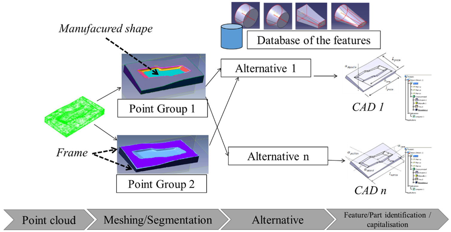
The scanning phases are considered already done, and a full point cloud is considered the inputs of the PHENIX methodology. To start the CAD(s) reconstruction, the user has to specify the adopted point of view from which to perform RE. The point of view is linked to the RE context (c.f. Table 2). A ‘point of view’ is called an ‘alternative’ in the PHENIX methodology. These are modelling assumptions that the user can have during the CAD generating process. For example, in Figure 4, the CAD modelling could be organised to drive the shape in the middle according to the sides of the frame while also organised to drive the shape in the middle according to the centre of the frame. The alternative definitions are freely defined by the user and can be organised as desired. Alternatives are created if there are different modelling routes, for example, with manufacturing or functional views. The CAD generation is done according to the selected or created alternative. The features already in the database are filtered according to the alternative and then proposed to the user. Using different segmentation algorithms (manual splitting/growing of regions), the user is assisted along the best-fit operations. This process consists of checking segmentation, selecting point groups, selecting features from a database and performing the best-fit operations.
Metrics of the PHENIX system.
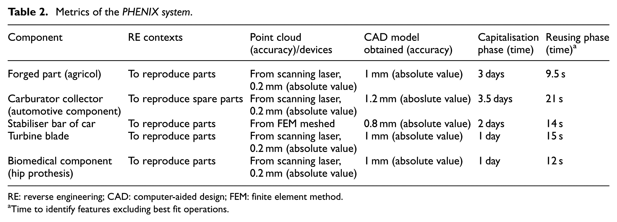
RE: reverse engineering; CAD: computer-aided design; FEM: finite element method.
Time to identify features excluding best fit operations.
Features are thus selected from the knowledge base and associated to specific point groups. One parametric feature can be associated to one or more point groups.
The feature definitions, identifications and alternatives are built using the following rules:
‘Alternatives are generated when more than one feature is associated to one point group. If two features are associated to one point group, then two alternatives are considered’.
All the alternatives describe the same part to be managed in a PDM system.
The PHENIX methodology requires an important initial capitalisation task. Indeed, the feature database is initially empty. To fill it, it is necessary to create all the required features and to define their parameters. For this, a sketcher programme based on the skin and skeleton method 23 helps user to draw the skeleton through its sections, its path and its behavioural law (for multi-sections) with geometrical parameters, and at the end, to determine the skin, such as the extrusion/removal material. This capitalisation phase is therefore a time-consuming task and is comparable to the boundary representation (B-REP) modelling and constructive solid geometry (CSG) modelling of classical modellers (see the ‘Discussion’ section for some details and estimates). The next focus of this contribution is to propose the knowledge framework and to expose the reuse capacity of the PHENIX methodology in routine RE activities.
The extended model is proposed from extensions of CPM through inheritance relationships in order to integrate the different types of knowledge. The next subsection presents this extension framework.
CPM – extension framework for knowledge modelling
Extension from the CommonCoreRelationship and CommonCoreObject classes is proposed as a means to address two management aspects: (a) for management of the RE project, the CommonCoreObject is adequate via the ‘Artefact’ and ‘Feature’ classes to manage the RE process mainly in terms of feature reconstruction; and (b) the RE knowledge framework extension via the ‘CommonCoreRelationship’ class is needed to manage the alternatives.
The class ‘constraint’ enables to express the rules required to drive the obtained CAD model.
Figure 5 represents an extract of a CPM core in which the links of both management aspects of the extension are mentioned.
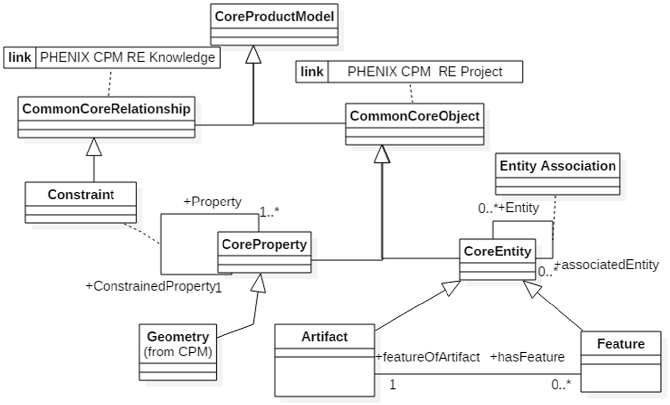
Core of the CPM model used for the extension.
CPM extension to manage an RE project framework
The ‘RE project’ class defines a project’s data such as the name and the person in charge of the project. This class is associated to the class ‘Artefact’ which is considered to describe the product reference. The point cloud data and the group of points are stored in the ‘PointCloud’ and ‘PointGroup’ classes, respectively, including links to the data files (STL, ASCII, etc.).
Figure 6 presents the extended model of the RE project.
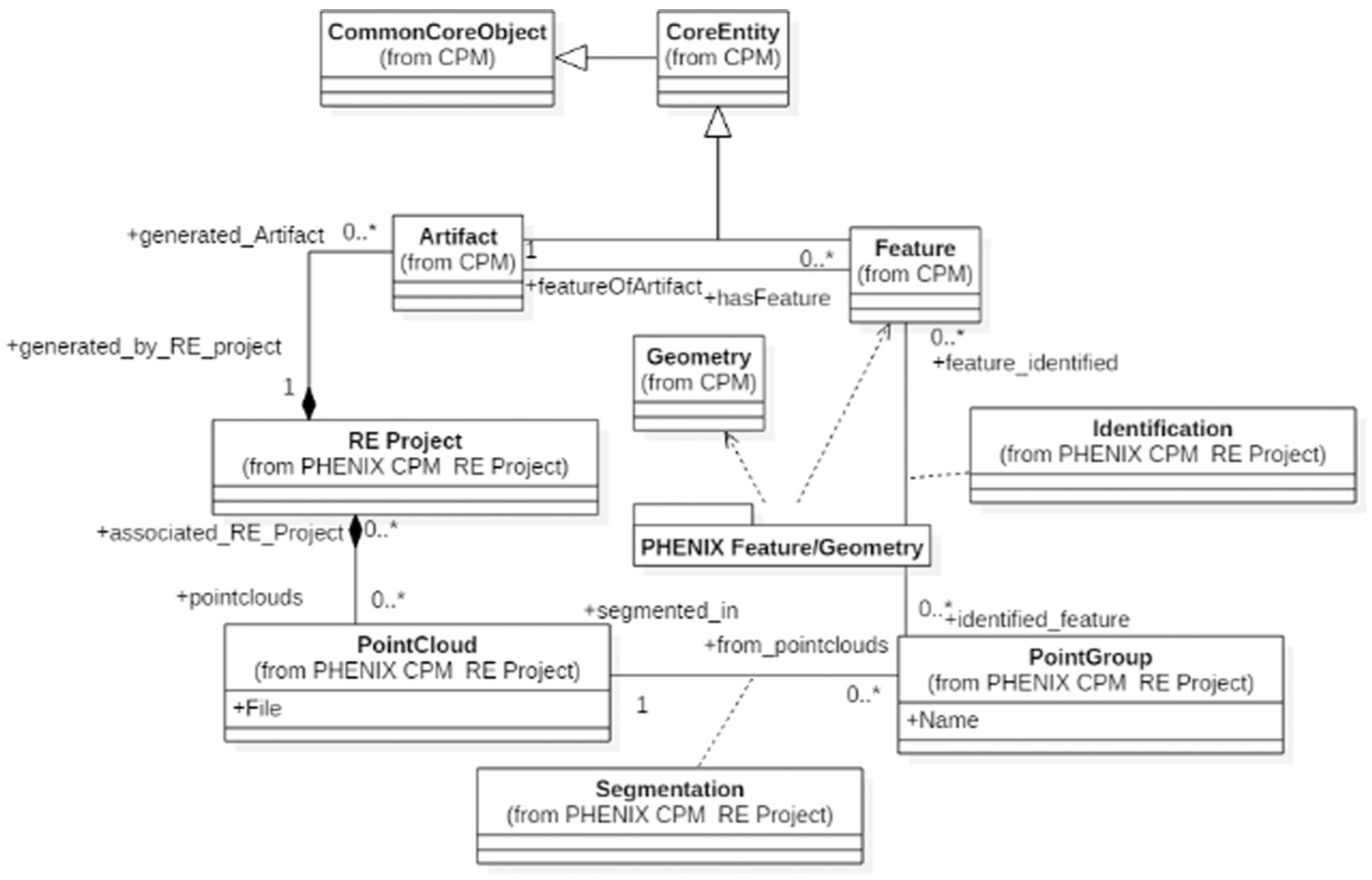
CPM extension: RE project framework.
The representation of the results of the RE process is also managed. The diagram class is thus composed of a ‘Segmentation’ class to maintain the information on the algorithms used, and the ‘identification’ class to associate a feature in the point groups. This identification could be manual or automatic using matching algorithms. The ‘Feature’ and ‘Geometry’ classes are reused from the CPM but linked by a ‘PHENIX feature/geometry’ package which allows the associated CAD shapes to be described. The associated shapes are modelled using the concepts of skin and skeleton method introduced by Skander et al. 23 and Durupt et al. 24 (see Figure 7).
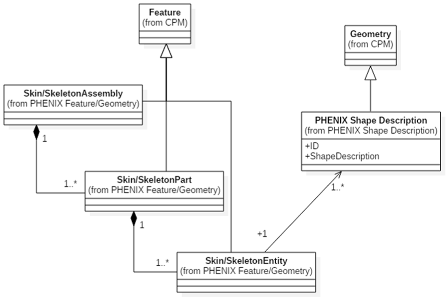
CPM extension: feature/geometry, and skin and skeleton concept.
CPM extension to manage RE knowledge
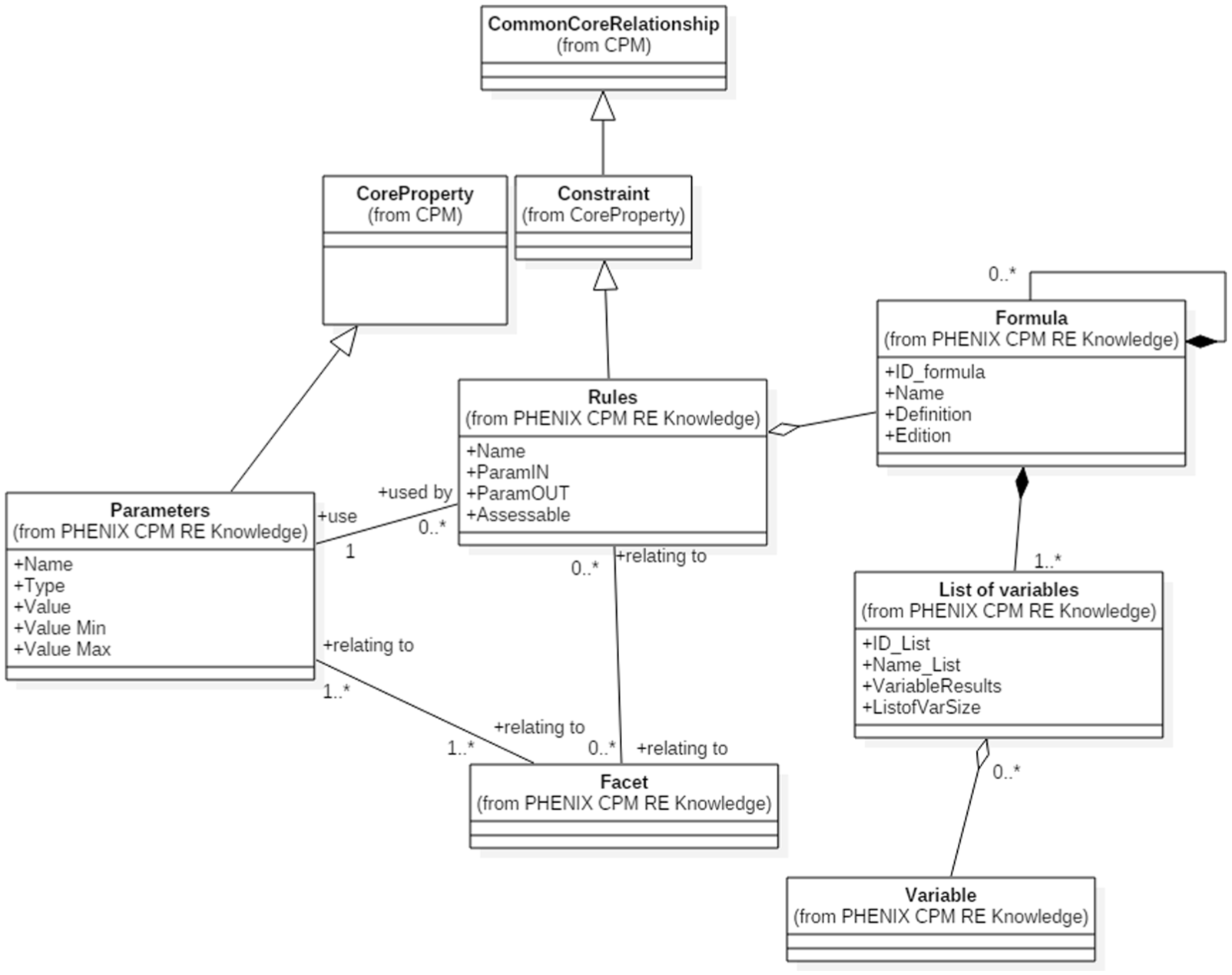
Knowledge expertise integration is done through the classes ‘Parameter’ and ‘Rules’ (c.f. Figure 8). These classes are integrated by means of a specialisation of the ‘CoreEntity’ and ‘Constraint’ classes. The expertise is represented by the class ‘facet’. A facet allows considering the alternatives, as mentioned above.
CPM extension: RE knowledge framework.
The ‘Rules’ class is used to represent the relationships between the parameters of a CAD model dedicated to an expert representation or to describe the transformation rules of the skin and skeleton model to a dedicated expertise representation of the product.
A rule is defined as a generic formula which is applied to a list of variables. The application of a rule consists of replacing the variables of the generic formula by valued parameters.
A rule or a parameter could be associated to a facet dedicated to an expertise and then to a ‘CommonCoreRelationship’ class to obtain the skin and skeleton shape.
This extended model had been instantiated and tested in a real industrial context. The next section explains and shows some interfaces of the PHENIX system with this extended CPM framework.
The skin and skeleton concept (Figure 7) facilitates the dimensioning, the parameterisation and constraint addition using semantics on the geometrical feature model. This concept is integrated in the extended CPM via the ‘Feature’ class which is linked to the ‘Artefact’ class. Three kinds of features are added to the model:
Entities, represented by the ‘Skin/SkeletonEntity’ class, allowing a basic feature to be drawn;
Part, represented by the ‘Skin/SkeletonPart’ class, which allows the feature representing the part to be drawn;
Assemblies of parts, represented by the ‘Skin/SkeletonAssembly’. The knowledge framework is planned but not yet implemented.
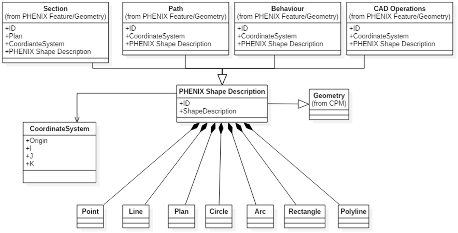
The shape description is proposed according to the extended model shown in Figure 9. The ‘PHENIX Shape Description’ class is the central class to define all geometrical shapes and their associated coordinate systems.
CPM extension: shape description.
PHENIX system– extended framework for RE projects
The extended RE CPM framework is implemented in a PHENIX system. This section uses the case of an automotive stabiliser bar (see Figure 10) to illustrate the operation of this system. This use case comes from an RE problem encountered by a company that designs and produces stabiliser bars from FEM-optimised mesh models.
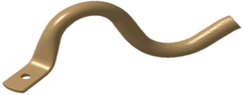
Automotive stabiliser bar – FEA meshed model.
The Original Equipement Manufacturer (OEM [the car manufacturer]) provides an optimised finite element analysis (FEA) meshed model. The provider has to make a parameterised CAD model with dedicated parameters, such as the diameters of the sections, the width of the bar and the axle spread. Next, the provider uploads the 3D CAD model onto the OEM’s PLM system and then waits for manufacturing orders to produce a batch of specific bars. Hence, the provider is confronted with RE problems (going from the initial 3D mesh to the parametric CAD model). It is their routine activity and is done every month. The FEA meshed model is the only input data available to produce the design. The RE is thus necessary to obtain the required parameterised CAD model.
The RE PHENIX process starts with segmentation techniques (region grouping and manual splitting). Figure 11 shows the main interface of the PHENIX system, where it is possible to segment mesh (only vertices are shown in the interface) from a split plane or region-group segmentation. The aim is to split the meshed model into areas in order to fit a ‘Skin and Skeleton Entity’ into the model. Manual segmentation to split the beginning of the bar, accomplished by plane handling, is shown in Figure 11.
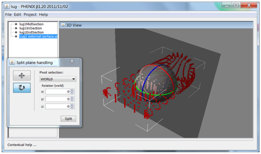
Manual segmentation in PHENIX system– split plan handling.
The capitalisation step has already been done. According to the instantiation example explained earlier, the skin and skeleton entity of the beginning of the part is already in the database. In the interface shown below, ‘Category’ represents the facet; in this case, FEA parameterisation is considered. In the field ‘Skeleton’, the user chooses the entity; here, the beginning of the part. To end, the user selects the identification mode in the field ‘Algorithm’; here, the mode is manual by least-squares approximation. The manual algorithm is based on the parameter tags where the user in the 3D interface selects the main cloud, the final section, the initial section and the mid-section of the cloud split of the points. The 3D entity is the next fit and the parameters are valued. The list of parameters and values is shown in Figure 12. A CAD model dedicated to an expertise facet is thus made, entity by entity.
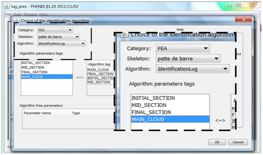
Skin and skeleton feature identification from the database.
According to the same work, the parameters are listed and valued. The model is dynamic; every parameter is editable, and the user can change their values. Global redesign can now be possible.
According to the algorithm tag, the feature is fitted into the point cloud area (Figure 13). Scoring results are shown in a window ‘Entity skeleton editor’. The fitting score could be done to a scale of 0.001 mm. In this case, the exterior diameter is changed by the user to 21 mm, which is considered in Figure 14.
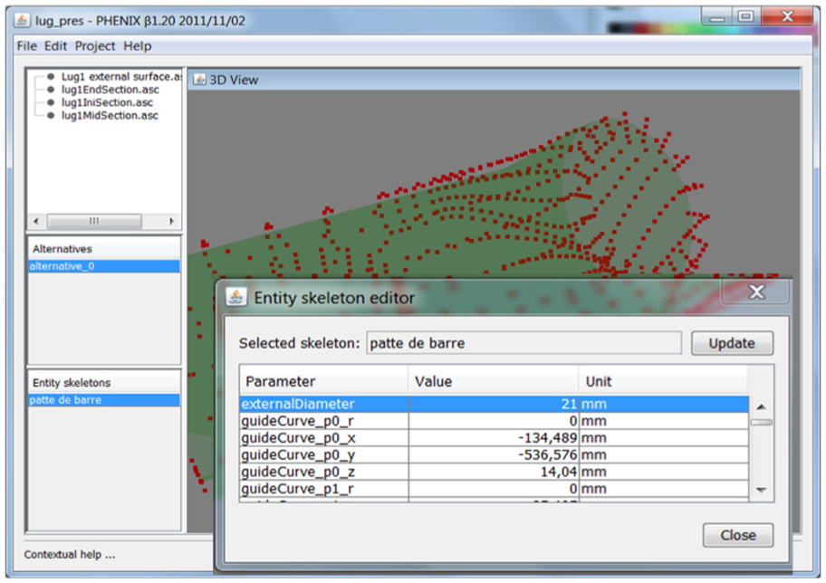
Feature identification with parameterisation.
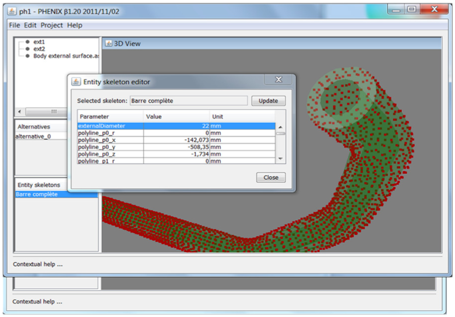
Global redesign possibilities – the part is structured as a parameterised CAD model.
A CAD model is obtained by the sequential fitting operation of skin and skeleton entities. The database of PHENIX system also contains the skin and skeleton of a part, and thus, it is possible to fit it into a point cloud of a part. The interface below shows the fitting scoring (Figure 14). In the same way, all parameters valued are editable and lead the topology, thereby enabling redesign. Users may change and lead the topology by changing parameters as shown in Figure 14. ‘External Diameter’ is editable and leads to the CAD model development.
To end, CPM framework explorer is provided to the user in order to have an evolving overview of the objects, such as the facet, the skin and skeleton, and the rules (Figure 15).
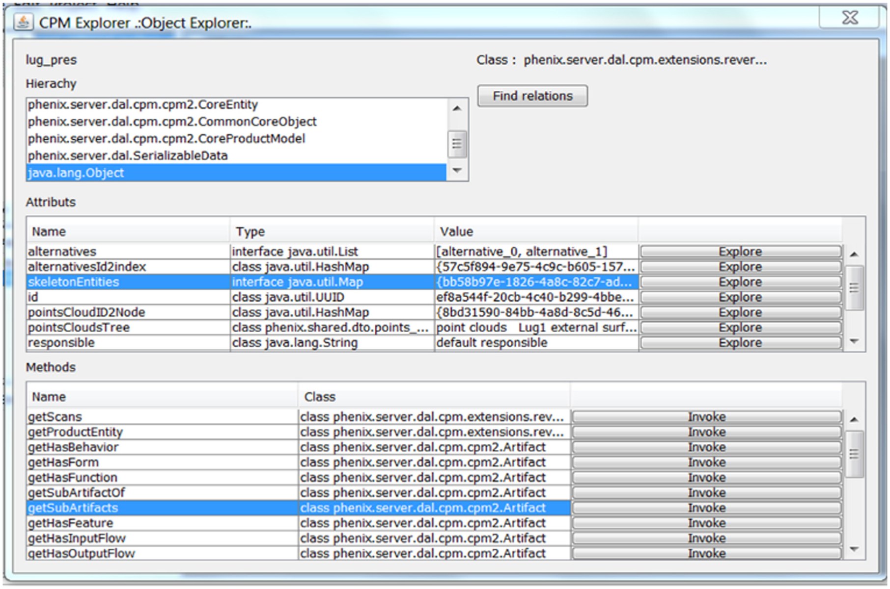
RE-extended CPM explorer.
Discussion
This contribution proposes a knowledge model to support RE activities in order to quickly integrate RE parts in the detailed design phase. A knowledge framework based on a CPM extension is proposed. The CPM extension allows the RE project and the RE knowledge to be managed. It covers shape, feature and geometry descriptions and the integration of expertise, thus allowing redesign possibilities. The novel aspect is both to propose a knowledge framework allowing to obtain relevant information for RE activity and to propose a detailed workflow of the capitalisation and reuse of parameterised features according to the modelling alternatives.
The knowledge framework was developed and then tested with an automotive stabiliser bar provider (part of the ground link components). A capitalisation step was necessary to fill the database with the required features. The skin and skeleton approach assists users to draw features, rules and parameters. It is a time-consuming task, but once done, it can be utilised multiple times. Two days of capitalisation was necessary to complete the database, with the provider assisted by the research team. The provider has RE cases at least once a month and needed between 5 and 10 h to obtain a CAD model according to the level of complexity. This means that the company spent between 50 and 120 h/year to do RE. In the case of stabiliser bars, by using PHENIX, the time to obtain the CAD model now only takes 1–2 h, including fitting shapes and redesigning operations. The new RE time can thus be estimated between 12 and 24 h/year. This time reduction is possible because PHENIX supports routine RE. The car stabiliser bar case study is composed of 4–8 features and is considered through two facets (FEA and manufacturing alternatives).
The PHENIX system is not used for metrology (inspection) but for redesign because the parameters are editable and users can change their value. The PHENIX system has been tested in other industrial settings, such as forged automotive parts, biomedical components and machinery spare parts (see Table 2).
In these cases, the point cloud was obtained with a laser scan arm. The accuracy (absolute value) is 0.2 mm after the meshing phase. The distance (absolute value) between the generated CAD and the mesh is close to 1 mm. This level of accuracy is acceptable because the CAD shape can be easily changed by the driving parameter.
Some technical improvements in terms of software implementation (GUI, etc.) can be further developed, including the following:
Quality of the point cloud was not considered. Information about this should be added as an indicator of noise. The user could then adapt the new value of the parameters;
Best-fit score on feature fitting could be made visible. The user could then better assess new parameter values;
Feature modelling could be changed and become more efficient than the skin and skeleton approach, as it imposes the manner of the geometric modelling.
Some conceptual improvements could be made to the usage of the PHENIX approach; indeed, three cases should be addressed:
If the initial capitalisation step is not done, the feature database will be empty and therefore has to be filled. The first thing to do is then to model all the necessary features. The time needed is estimated to be equal to that of modelling with standard RE software, although this needs further testing;
If the initial capitalisation step only partially covers the needed parts, some features will be missing to cover the entire point cloud. A just-in-time capitalisation step is therefore necessary to finish the CAD model. Testing of some parts should also be addressed in the PHENIX system;
If the capitalisation step is already done and all the necessary features and parts are modelled, the CAD is completely obtained by fitting features on the points group. The fitting execution time can be reduced by considering other matching algorithms, such as graph-based reasoning.
Concerning the reusing step, to recall, PHENIX consists of fitting features into a point cloud. The CAD models are built by a single feature or feature by feature. The joint between features is not yet taken into account. All of the generated CAD models consist of features including holes or interferences. It should be possible to consider the precedence of the features and for the user to control the correct fitting and positioning online (during the modelling).
The PHENIX approach and its implementation have been presented to a cluster of companies specialised in automotive, aeronautical and biomedical components (Table 2). It appears that an ideal of PHENIX system would automatize the capitalisation step (to bypass the skin and skeleton in reusing the native CAD modeller) and keep the user’s ID confidential, and it would only focus on proposing modelling and fitting of CAD parts. For these potential partners, the feature-by-feature implementation seems less relevant. The alternatives are important but they would have to be considered as a versioning of CAD models.
The knowledge framework based on extended CPM is universal but its implementation (reusing phase) is unique for each company. An implementation pattern could be brought in to help industry players to install PHENIX. Hence, a deep study on the acceptance and efficiency of GUI has to be done and a proposal of a feature taxonomy studied in order to help users to class the features. Connectors between CAD modellers and PHENIX methodology need to be proposed to merge PHENIX in native CAD environments.
Some other methodological aspects still need to be taken into account, such as the assemblies of components and heterogeneous data integration. Indeed, RE is not only dedicated to one part but also to whole systems (assemblies of parts). Also, in the industrial context, the starting point is not only a point cloud but can also include other files such as images, photos and drawings. These types of heterogeneous data should be evaluated and integrated, a process that will require a more advanced knowledge framework for RE.
Footnotes
Acknowledgements
The PHENIX project (Product History based reverse ENgineering : towards an Integrated eXpert approach – no.ANR-08-COSI-011) was created to work on this knowledge model for RE activities. The CAD and CAD parameters obtained by PHENIX represent the expertise information. Redesign is thus possible through these parameters. The CPM model from NIST was used and extended to support the RE process.
Declaration of conflicting interests
The author(s) declared no potential conflicts of interest with respect to the research, authorship and/or publication of this article.
Funding
The author(s) received no financial support for the research, authorship and/or publication of this article.