
Abstract
321 and 410 stainless steels were brazed using 400 W pulsed Nd:YAG laser source with AMS 4777 filler metal for various joint clearances. Optical microscopy and scanning electron microscopy were used to study the microstructure of all specimens. Mechanical properties (microhardness and tensile test) of all specimens were evaluated. The wetting, spreading, and flowing of AMS 4777 filler metal on substrates during this process were modeled using finite volume model. The equations of conservation of mass, conservation of momentum, and conservation of energy were solved in FLUENT software for calculating volume fraction and liquid fraction. AMS 4777 filler metal shows excellent wettability on the 321 and 410 stainless steels. The filler metal and specimens mainly consist of nickel solid solution (Ni), chromium boride (CrB), and nickel boride (Ni3B). The average microhardness for specimens in seam is 492 HV. The tensile strength of specimens changes from 200 up to 480 MPa due to various joint clearances. The higher tensile strength of 321 stainless steel specimens in comparison with 410 stainless steel specimens is due to less wetting angle and more spreading width of filler metal. The simulated results show that this model can be used for predicting geometry of joints at various joint clearances.
Keywords
Introduction
321 and 410 stainless steels are austenitic and martensitic steels which are used in high temperature applications such as aerospace components. Heat-affected zone cracks have been observed during welding of 410 SS due to high hardenability of this steel. Also, 321 SS is highly susceptible to the intergranular cracks in the heat-affected zone of the weld. Therefore, repairing of these components with welding process is difficult.1–3
Brazing process can be used as one of the alternative methods to repair the parts. Commercially available brazing filler metals used for joining stainless steels are copper, silver, nickel, cobalt, platinum, palladium, and gold-based alloys. Nickel-based filler metals exhibit good corrosion resistance, oxidation resistance to temperature up to 982 °C–1093 °C, and high strength at elevated temperatures. AMS 4777 is one of the most widely used nickel-based filler metals.4,5 Boron and silicon in this filler metal, as the melting point depressant elements, form intermetallic compounds which are extremely hard and brittle. These intermetallic compounds are detrimental to the mechanical properties of the brazed joints. 6 Therefore, time at brazing temperature and quantity of filler metal should be controlled carefully. 7
The joint can be heated in many ways, which are commonly categorized by the actual method of heating. There are six commonly used methods: (1) torch brazing, (2) furnace brazing, (3) induction brazing, (4) dip brazing, (5) resistance brazing, and (6) infrared brazing. Lesser known heating methods include (1) microwave brazing, (2) weld brazing, and (3) laser brazing. 5 Singh et al. 8 proposed microwave material processing as one of the novel methods of material processing which can satisfy the present requirements and can yield a better product at reduced costs and processing time. Srinath et al. 9 used microwave energy for joining of austenitic stainless steel (SS-316).
Laser brazing is a new technique successfully used in brazing of various materials.10–12 Its major advantage over other brazing procedures is that the joint area can be heated precisely without heating the entire workpiece to the liquidus of the brazing filler metal. This limits the flow of the braze filler metal to the area heated by the laser beam and precludes any flow due to capillary action. Rapid thermal cycle in this process can greatly forbid from the growth of brittle interfacial reaction layer between the base metal and AMS 4777 filler metal. 13
Khorram et al. 12 investigated laser brazing of austenitic stainless steel and martensitic stainless steel with BAg-8 filler metal. They concluded that the sound joints can be obtained by BAg-8 filler metal. Laser brazing of alumina and steel was performed by Rohde et al. 14 Frank and Ungers 15 developed a system for coaxial control of laser brazing process between aluminum and steel. Li et al. 16 laser brazed Mg alloy to mild steel and Mg alloy to stainless steel using AZ31 filler metal. They studied microstructure and mechanical properties of joints in both cases. Janssen et al. 17 suggested a fatigue crack path model to illustrate the differences in fatigue behavior of laser brazed joints made with dual phase and transformation-induced plasticity steels. Dharmendra et al. 18 laser brazed zinc-coated steel (DP600) to aluminum alloy (AA6016T4) using zinc-based filler metal. They found that heat input between 60 and 110 J/mm results in higher mechanical resistances of the joints. Mathieu et al. 19 investigated laser brazing of steel to aluminum with filler wire of 88% Al and 12% Si. Li et al. 20 studied the effect of laser welding–brazing parameters on the bead geometry and joint strength of Mg alloy and Zn-coated steel. They found optimized process parameters for maximum joint strength. Laser brazing of aluminum alloy to steel with ER4043 filler metal was carried out by Sun et al. 21 They concluded that the wetting of filler metal on the bevel surface of the steel can be improved by zinc coating. Hirsch et al. 22 studied the brazeability of five commercially automotive zinc-coated steels. They found that electro-galvanized steel exhibits the best brazeability among the investigated materials. Kim et al. 23 brazed a tungsten carbide cutting edge onto a stainless steel shank using silver filler and investigated the machining properties of the fabricated tools. They observed an abnormal wave pattern on the cutting surface when using the brazed tool due to woven structure of the workpiece. Agba et al. 24 investigated the effects of autobrazer parameter variations on the quality of return bend joints. They concluded that the repeatability of the brazing process and the production of high-quality joints can be guaranteed.
Numerical simulation of laser brazing process can help in comprehensive understanding of this process. The wetting behavior of the silver-based filler metal on various substrates in the laser brazing process was investigated by Khorram and Ghoreishi. 25 In this model, the contact angle exhibited maximum percentage of error about 8%. The laser welding-brazing process of cylinder shell was simulated by Yixia et al. 26 In their analysis, they did not consider solidification and melting. Chen et al. 27 developed a model for simulating the spreading of CuSi3 filler metal. They concluded that dominant driving force for flowing of filler metal is surface tension. Park and Na 28 studied the thermomechanical behavior in 304 stainless steel studs to 5052 aluminum plates laser brazed joints. The numerical results showed that stress peaks exist along the joining interfaces due to mismatch in thermal and mechanical properties of materials. Mohanty et al. 29 simulated keyhole mode laser welding. This model could predict the weld bead profile encompassing a wide range of materials under different operating conditions. Otto et al. 30 developed a model which can simulate various laser materials processing such as welding, cutting, and drilling.
There are no reports about laser brazing of 321 SS and 410 SS with AMS 4777 filler metal. In this research, repair brazing of 321 SS to itself, and separately, 410 SS to itself with AMS 4777 (a nickel-based filler metal) is investigated. The evolution of microstructure and mechanical properties of specimens are carried out. Filler metal spreading on 321 SS and 410 SS substrates are studied for various joint clearances. For clear understanding of laser brazing process of 321 SS and 410 SS substrates with nickel-based filler metal, a two-dimensional (2D) model is constructed by GAMBIT software and FLUENT software. The multiphase flow, solidification and melting, and heat transfer are considered in this model.
Experimental procedures
Materials
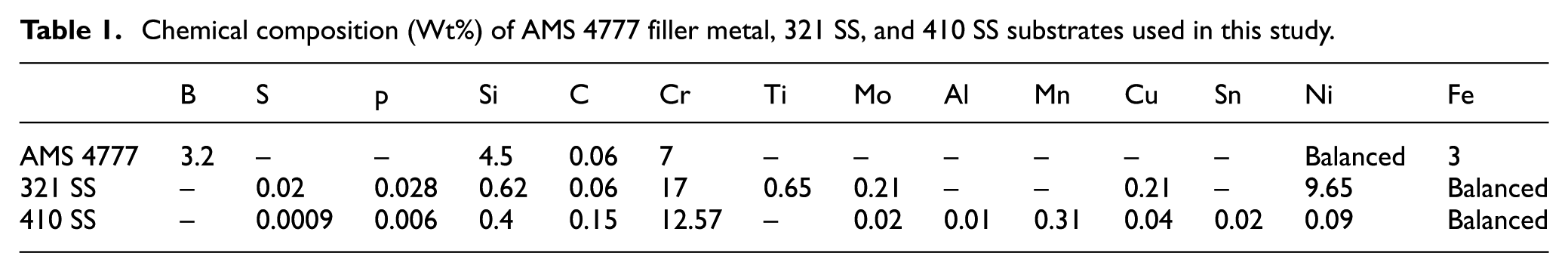
321 SS and 410 SS, as sheets with thickness of 1 mm, were used as the substrate. The substrates were cut with dimensions of 120 mm long × 25 mm wide. AMS 4777 filler metal with a diameter of 2 mm was used to join the substrates. Solidus and liquidus temperatures of filler metal were 971 °C and 999 °C, respectively. The chemical compositions of AMS 4777 filler metal and the substrates are given in Table 1.
Chemical composition (Wt%) of AMS 4777 filler metal, 321 SS, and 410 SS substrates used in this study.
Experimental setup
The laser beam of a pulsed wave 400 W Nd:YAG was used to perform laser brazing process. The wavelength of the laser was 1.06 μm. The laser beam was focused using lens with a focal length of 75 mm to gain a spot diameter of 0.25 mm. The laser equipment had a pulse duration, pulse frequency, and pulse energy ranging from 0.2 to 20 ms, 1 to 1000 Hz, and 0 to 40 J, respectively.
The edge and the surface of substrates were degreased with acetone prior to brazing. After cleaning, the substrates were placed in a fixture in a butt configuration and then the filler wire was put and fixed at brazing seam before doing the experiments. Two ground plates with thickness of 3 mm were placed on the substrates and clamped in their positions to prevent the distortion of specimens during laser brazing process. The setup of laser brazing process equipment is shown in Figure 1.
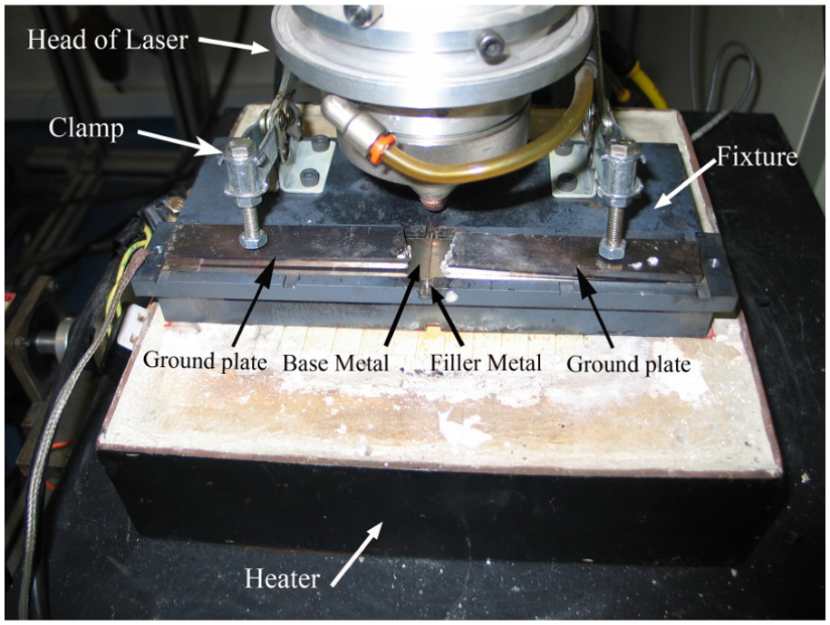
Setup of laser brazing process equipment.
In the beginning of laser brazing process, the laser beam had a distance from the filler metal. The laser beam moved, and the heat was absorbed by the filler metal. Then filler metal melted and the phase changed from solid to liquid with absorbance of the equivalent latent heat. At the end of process, the laser beam exited from the specimen. The experiments were performed three times at various joint clearances (0.05 mm, 0.08 mm, 0.15 mm, 0.4 mm) using the following parameters: laser power: 205.2 W, pulse width: 1.7 ms, pulse frequency: 100 Hz, traveling speed: 1.3 mm/s, shielding gas type: argon, gas flow rate: 30 L/min, and preheating: 350 °C, which were adjusted as the best setting parameters according to previous investigation. 10
Characterization techniques
After laser brazing, the specimens were cut transverse to the direction of the laser track. Standard metallographic procedures were used to study the microstructures in the transverse cross sections. The cross sections were etched with Kalling’s reagent (1.5 g CuCl2 + 33 mL HCl + 33 mL H2O + 33 mL ethanol). Microstructural observation of the filler metal and the specimens was conducted using an Olympus CX21 Optical Microscope (OM) and a Tescan Vega-3 LMU scanning electron microscopy (SEM). Energy-dispersive X-ray spectroscopy (EDS) was used to determine composition analysis in some cases. Measurement of laser brazing geometrical dimensions consisting of spreading and wetting angle was conducted using Clemex image analyzer software. Philips X’Pert-MPD X-ray diffraction (XRD) with a vertical T-T goniometer (190 mm radius) was used to analyze the phases present in the filler metal. It should be mentioned that X-ray source and scanning rate were a Cu-Kα and 1° min−1, respectively. Diffractogram was recorded for 2θ angles ranging from 10° to 135°.
A differential thermal analysis (DTA) machine (Rheometric Scientific STA 409 PC Luxx) was used to measure the physical properties of AMS 4777 filler metal such as specific heat capacity and latent heat. Vickers hardness tests were carried out on the cross sections of laser brazed joints as per ASTM E384 standard under a load of 1000 g for 10 s. Microhardness tests were repeated at least three times for each sample. In order to study the joint strength of the specimens as per ASTM E8M standard, tensile tests were carried out by universal testing machine with a cross-head speed of 1 mm/min.
Mathematical models
The wetting behavior of AMS 4777 filler metal droplet on 321 SS and 410 SS substrates were simulated for various joint clearances. A 2D transient model was used for simulating laser brazing process, in Cartesian coordinate system. The workpiece geometry, the mesh, and the boundary conditions were created in GAMBIT 31 for subsequent computational fluid dynamics (CFD) calculation in FLUENT software. 32 The simulation model is shown in Figure 2. The dimensions of the 2D domain were taken as 6 mm × 3 mm for decreasing the calculation time. In our setup, double precision of the software was used to analyze because the dimensions of domain was small. Also, only half of the workpiece was considered in simulation due to symmetry of joint about the centerline. The mesh around the joint line was maintained dense to calculate the joint geometry accurately. In order to reduce the calculation time, a coarse mesh was used for other regions of the model. Besides, the numerical domain consisted of solid phase (filler metal and substrate) and gas phase (air).
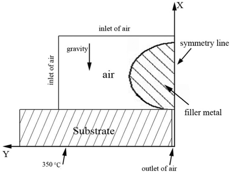
Simulation model.
Material properties
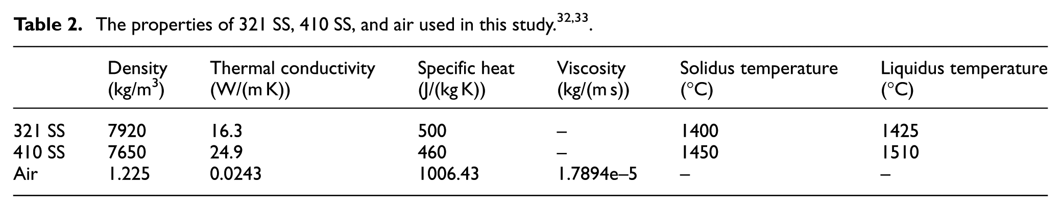
The properties of the substrates (321 SS and 410 SS), air, and filler metal (AMS 4777) used in the present calculations are given in Tables 2 and 3. A piecewise polynomial profile between the solid filler metal and liquid filler metal was considered due to discontinuities in properties. Physical properties of AMS 4777 filler metal consisting of specific heat capacity and latent heat were determined by DTA. The heating rate of filler metal was 10 °C/min. The DTA curve of AMS 4777 filler metal is presented in Figure 3. The endothermic peak in 979 °C–1007 °C corresponds to the melting of AMS 4777.
The properties of AMS 4777 filler metal in this study. 34
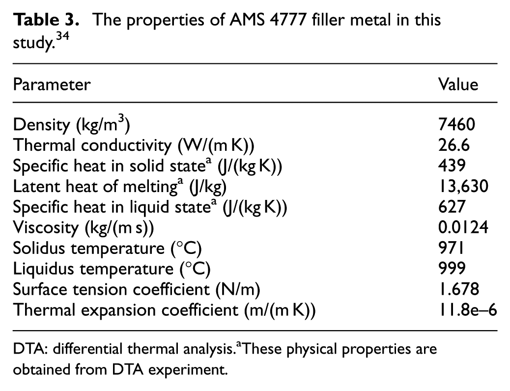
DTA: differential thermal analysis. a These physical properties are obtained from DTA experiment.
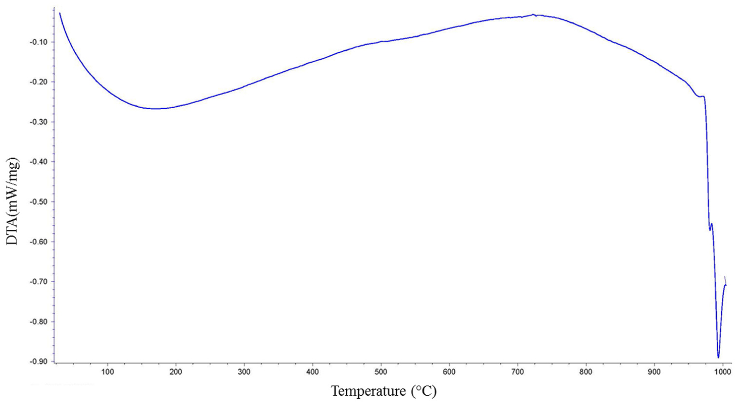
DTA curve of AMS 4777 filler metal.
Governing equations and boundary conditions
The equations of mass conservation, momentum conservation, energy conservation, and volume fraction 32 were used for simulating laser brazing process. These equations are explicitly as

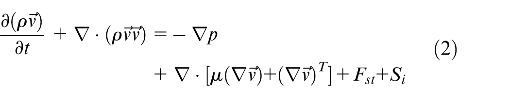
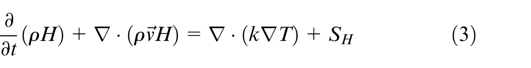
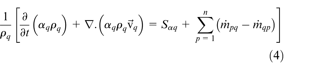
where H, T,
The following boundary conditions in this research took into consideration:
1. Filler metal edge
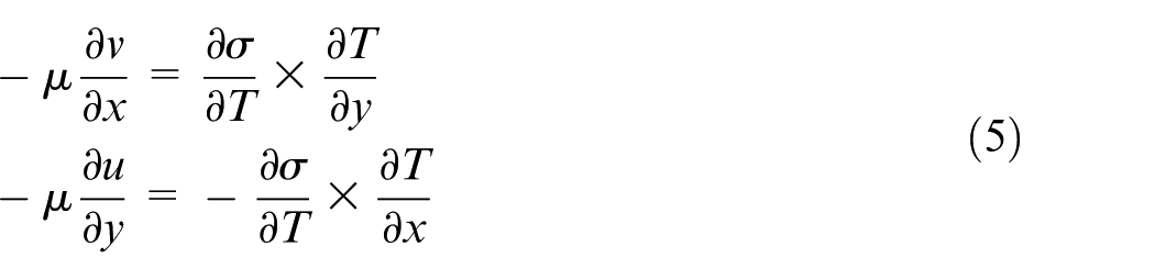
where u and v are the velocity along the positive x and y axes, respectively, and determined from Marangoni effect. σ is the surface tension 25
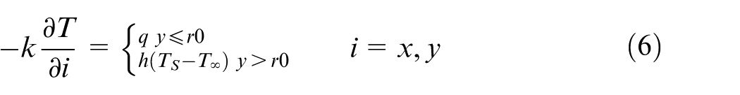
where k is thermal conductivity,
2. Solid region
Bottom wall
The temperature at this boundary was fixed at T = 350 °C.
All other walls
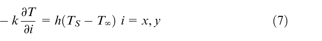
3. Symmetric line
4. Inlet and outlet of air
The pressure and the temperature were set as P = 105 psi and T = 27 °C, respectively.
5. Interface between solid region and filler metal

Heat source model
The laser beam was simulated in our model as a surface heat source with Gaussian distribution 35 using a user-defined function. This heat source can be defined as
Here, P is the total laser beam power, η is the absorptivity, and c is the laser beam radius.
Results and discussion
Wettability and joints geometry
Cross-sectional images of brazed butt joints for 321 SS and 410 SS at various joint clearances are presented in Figures 4 and 5, respectively. The filler metal exhibits excellent spreading and wetting on 321 SS and 410 SS substrates and completely penetrates into the joint gaps. Therefore, sound joints can be obtained by laser brazing process and the quality of joints is acceptable.
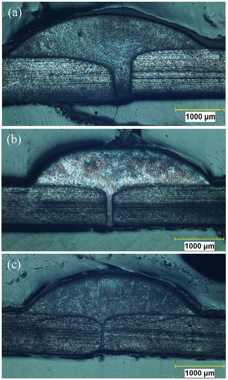
Macroscopic cross-sectional images for 321 SS laser brazed specimens: (a) 0.4 mm joint clearance, (b) 0.08 mm joint clearance, and (c) 0.05 mm joint clearance.
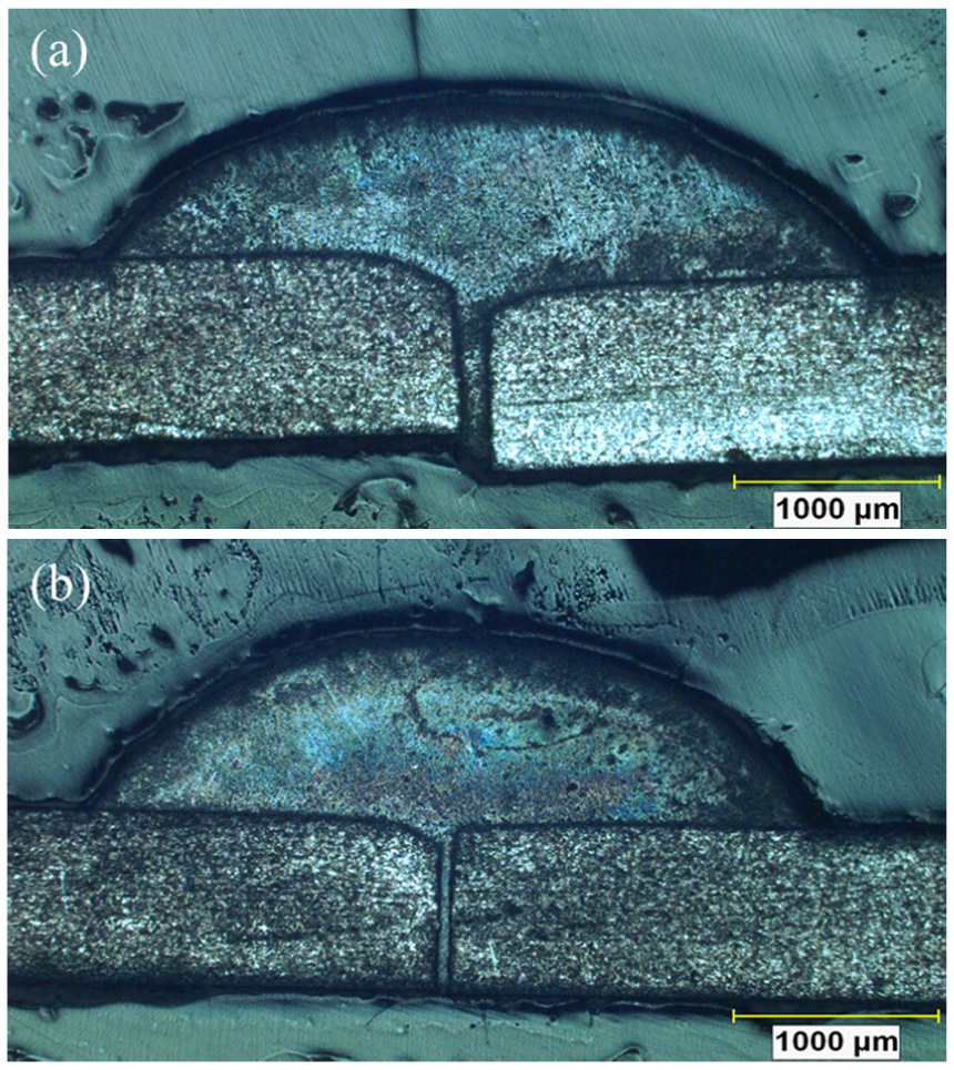
Macroscopic cross-sectional images for 410 SS laser brazed specimens: (a) 0.15 mm joint clearance and (b) 0.05 mm joint clearance.
The effect of joint clearance on wetting angle and spreading width of filler metal is shown in Figures 6 and 7, respectively. The spreading width increases from 3710 to 4150 µm and contact angle decreases from 50° to 35° for 321 SS laser brazed samples when joint clearance increases from 0.05 to 0.4 mm (Figure 6). On the other hand, the spreading width increases from 3700 to 4100 µm and contact angle decreases from 51° to 36° for 410 SS laser brazed samples as the joint clearance rises from 0.05 to 0.4 mm (Figure 7). The spreading width and wetting angle of AMS 4777 filler metal on 321 SS substrate are approximately similar to that for 410 SS substrate.
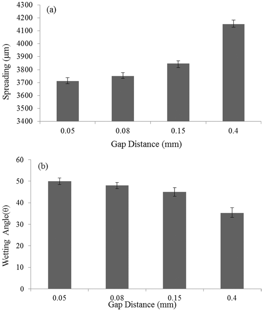
(a) Spreading width and (b) wetting angle of AMS 4777 on 321 SS substrate versus joint clearance. The error bars are deviation of the mean value.
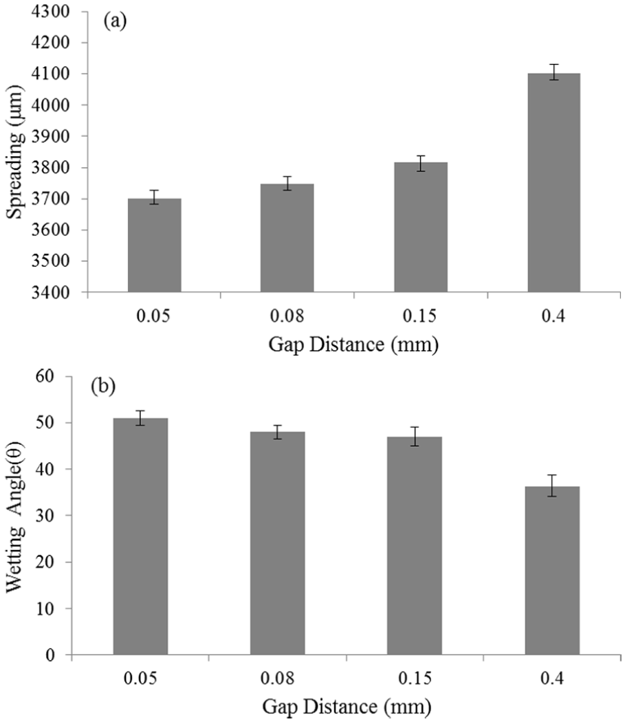
(a) Spreading width and (b) wetting angle of AMS 4777 on 410 SS substrate versus joint clearance. The error bars are deviation of the mean value.
Microstructural evolution
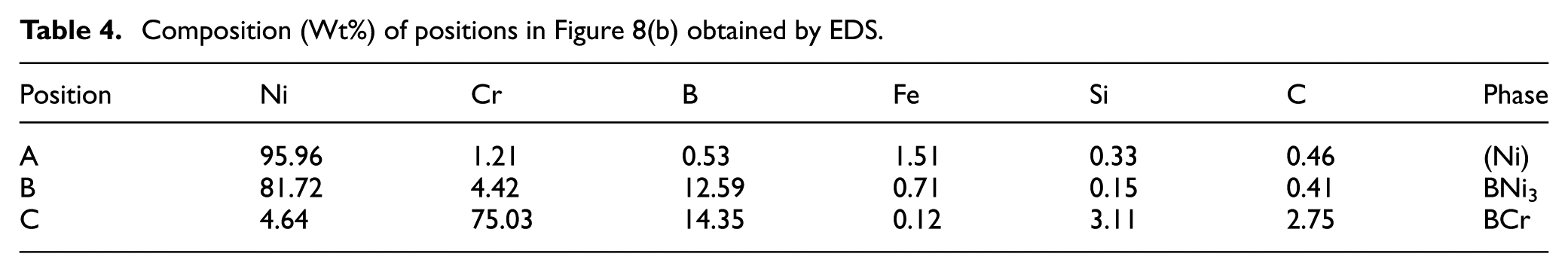
Figure 8 shows the SEM images of AMS 4777 filler metal. The filler metal consists of nickel solid solution (Ni), chromium boride (CrB), and nickel boride (Ni3B) according to the results obtained from XRD and EDS analysis (Figure 9 and Table 4).
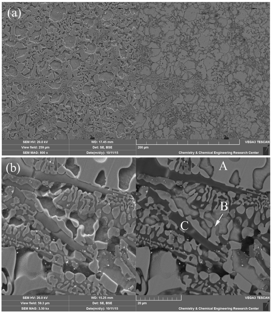
The SEM image of AMS 4777 filler metal: (a) overview and (b) high-magnification and EDS analysis.
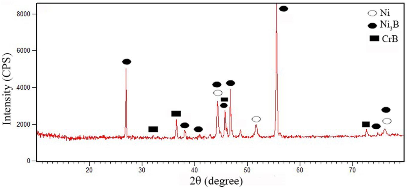
XRD patterns for AMS 4777 filler metal.
Composition (Wt%) of positions in Figure 8(b) obtained by EDS.
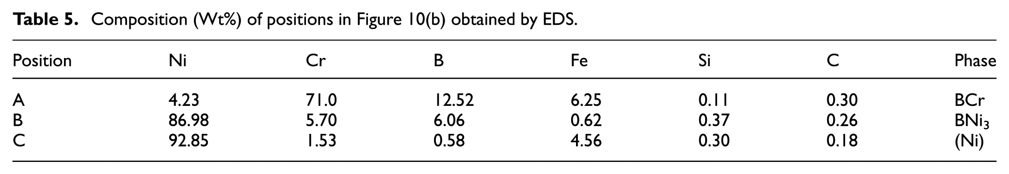
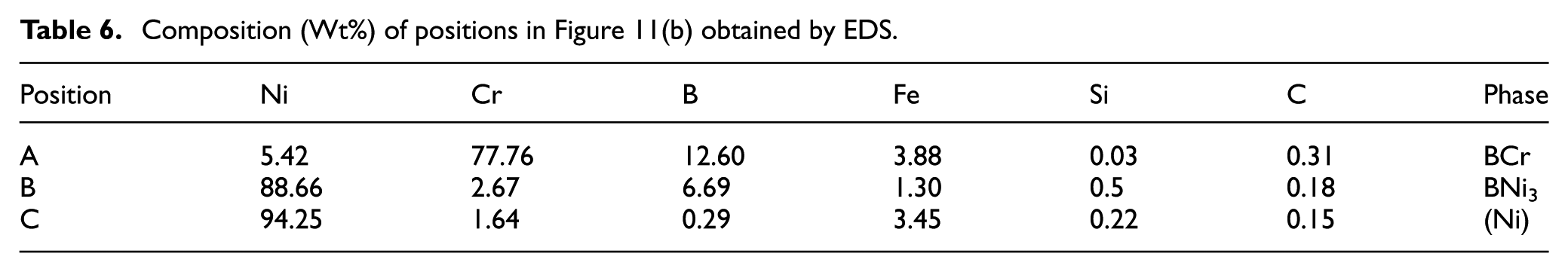
The SEM images (Figures 10 and 11) and EDS analysis of 321 SS/AMS 4777 filler metal and 410 SS/AMS 4777 filler metal (Tables 5 and 6) illustrate that the brazed joints comprise three phases: Cr-rich boride (zone A), Ni-rich boride (zone B), and Nickel solid solution (zone C).
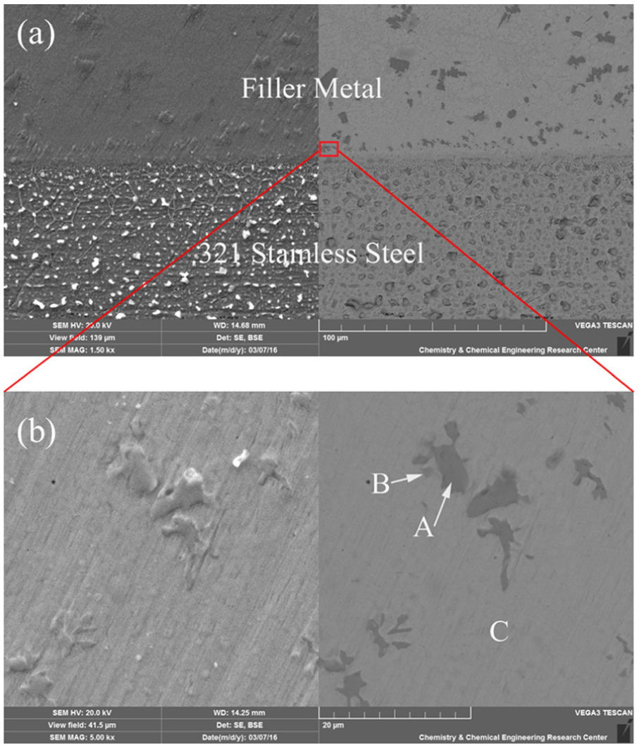
(a) Typical cross-sectional SEM image of 321 SS/filler metal interface and (b) part of (a) at higher magnification and EDS analysis.
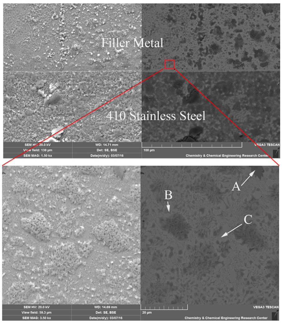
(a) Typical cross-sectional SEM image of 410 SS/filler metal interface and (b) part of (a) at higher magnification and EDS analysis.
Composition (Wt%) of positions in Figure 10(b) obtained by EDS.
Composition (Wt%) of positions in Figure 11(b) obtained by EDS.
Three ternary eutectic reactions of E1, E2, and E3 are observed in ternary alloy phase diagram of B-Cr-Ni. 36 The composition of the filler metal is close to E2. The transition reaction E2 can be expressed as

The dendritic (Ni) phase precipitates at solid/liquid interface at start of the filler metal crystallization. The temperature dropping leads to the eutectic reaction and formation of the eutectic structure (BCr, BNi3, and the nickel rich). It is in accordance with the experimental observation (Tables 5 and 6).
Rapid thermal cycle in the process causes non-equilibrium crystallization of filler metal. Therefore, the MPD elements which exist in the filler metal cannot diffuse to the base metal sufficiently and eutectic phases are observed in the seam (Figures 10(b) and 11(b)). Other researchers13,37 have reported similar eutectic microstructure in the brazing seam. The application of laser brazing process cannot completely avoid the formation of eutectic phases which are very hard and brittle. However, laser brazing is an effective way to prevent the growth of intermetallics at the substrate/filler metal interface.
Kirkendall voids, which are created by nonsymmetrical interdiffusion between the filler metal and substrates, have been reported by other researchers. 13 These defects are dependent on temperature and time. The interdiffusion between filler metal and substrates is minimized in laser brazing due to rapid thermal cycle. Hence, these porosities were not observed in this study.
Mechanical properties
Joint clearance is a critical factor affecting the brazing process because brazing depends on the principle of capillary attraction for distribution of the molten filler metal. High joint strength is obtained when minimum joint clearance is used. The joint clearance must be compatible with the brazing process, the base metal, and the filler metal.
The average tensile strength versus joint clearance for 321 SS and 410 SS laser brazed specimens is shown in Figure 12. The higher tensile strength of 321 SS specimens in comparison with 410 SS specimens is due to less wetting angle and more spreading width of filler metal. Increasing joint clearance from 0.05 to 0.4 mm causes decrease in the tensile strength from 480 to 210 MPa and from 460 to 200 MPa for 321 SS and 410 SS laser brazed substrates, respectively. 321 SS and 410 SS laser brazed specimens at 0.05 mm joint clearance demonstrate the maximum joint strength of 480 and 460 MPa, respectively.
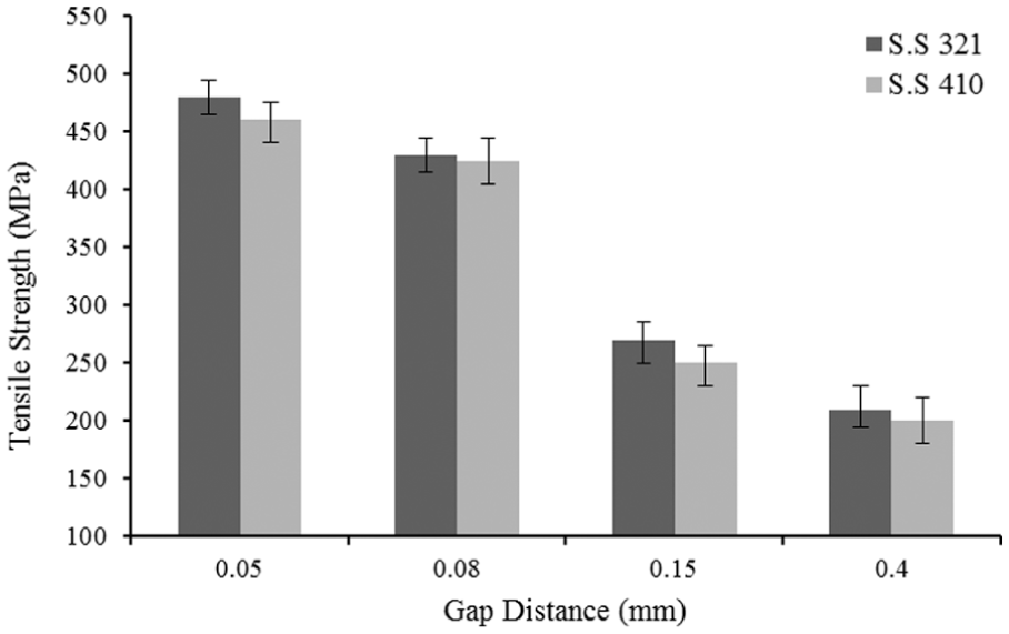
Average tensile strength versus joint clearance. The error bars are deviation of the mean value.
Other researchers have reported similar joint strength value using infrared brazing 13 and induction brazing. 38 The good joint strength of laser brazed specimens is due to less intermetallic agglomeration in the brazing seam. These brittle phases can destroy joint strength of specimens. Therefore, laser brazing process can be used successfully for joining 321 SS and 410 SS substrates with AMS 4777 filler metal.
Figure 13 shows Vickers microhardness profile of laser brazed joints for 321 SS and 410 SS substrates at 0.15 mm joint clearance. All specimens exhibit approximately similar values of microhardness, so only the microhardness value for one specimen is presented. The average microhardness of 321 SS and 410 SS substrates over a distance of 75 µm adjacent to the interfaces is 170 and 164 HV, respectively. This indicates that laser brazing has little effect on the substrates. Microhardness values rise rapidly and reach a peak of around 491 HV for 321 SS substrate and 493 HV for 410 SS substrate with increasing distance from the base metal to the laser brazed joint. Boron and silicon in BNi-2 filler metal have the possibility of forming extremely hard eutectic phases with nickel and chromium. In the laser brazed area, the less hard and brittle phases are formed. 6 So, the hardness of the laser brazed area (492 HV) is lower than the hardness of the filler metal (550 HV) due to less intermetallic compounds volume.
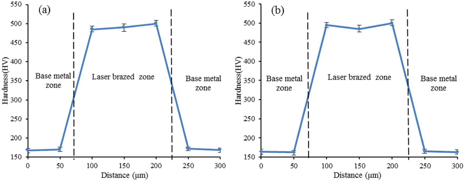
Microhardness profile of laser brazed sample at 0.15 mm joint clearance: (a) 321 SS and (b) 410 SS. The error bars are deviation of the mean value.
Simulation results of wetting behavior of AMS 4777 filler metal
Figures 14 and 15 show simulation results of wetting behavior of the filler metal droplet on 321 SS and 410 SS substrates for various joint clearances, respectively. The droplet wets the substrates and simultaneously penetrates into the joint gap with the lapse of time. The filler metal fills the joint gap with completion of brazing process. As seen in these figures, the filler metal fills completely the joint gap at all brazing clearances.
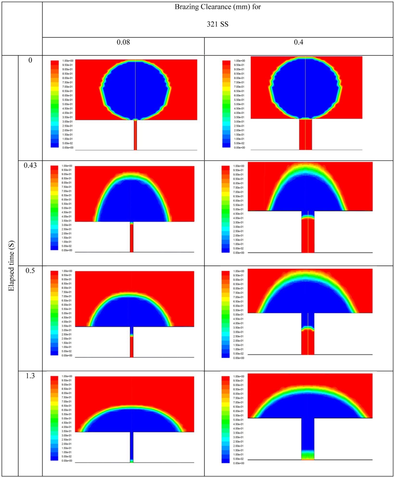
Wetting behavior of AMS 4777 filler metal droplet on 321 SS for various joint clearances.
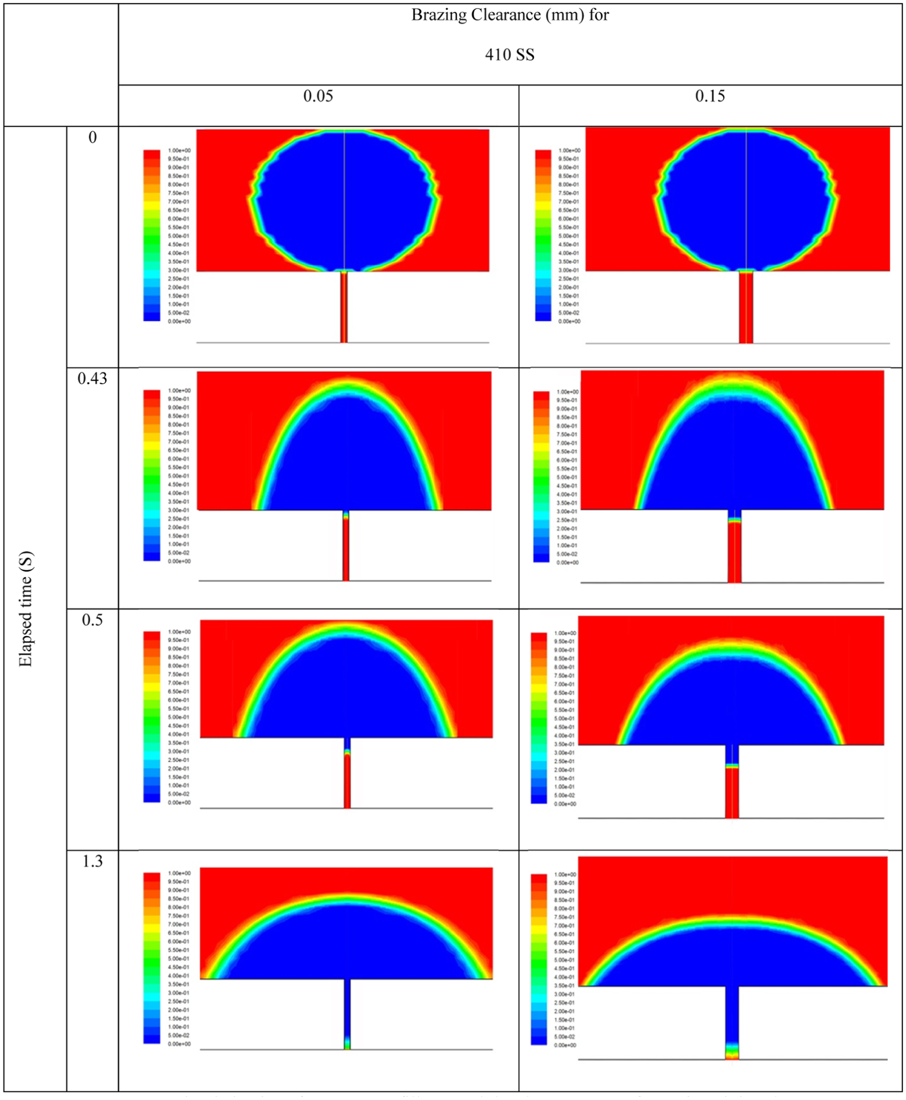
Wetting behavior of AMS 4777 filler metal droplet on 410 SS for various joint clearances.
Validation of simulation results
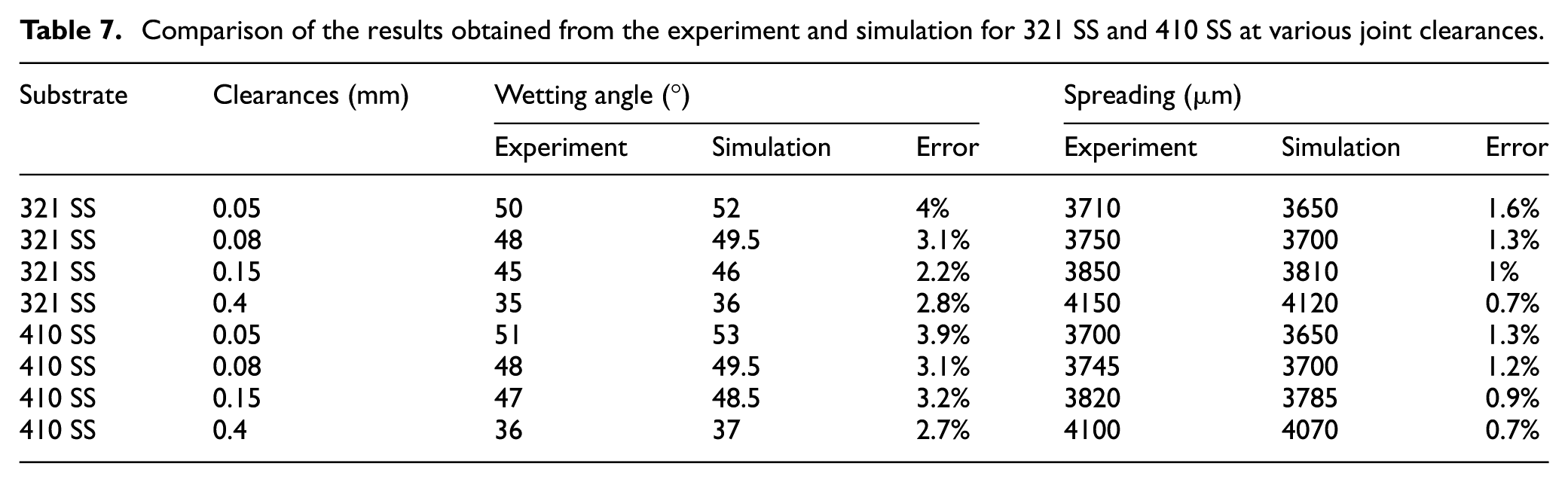
To verify the simulation results of wetting behavior of AMS 4777 filler metal on 321 SS and 410 SS substrates, the comparison of experimental and simulated joint cross section was performed for various joint clearances (Figure 16 and Table 7). As seen, the model can predict nearly accurate wetting behavior of AMS 4777 filler metal on 321 SS and 410 SS substrates at any joint clearances. The calculation results show less spreading and more wetting angle than experimental observation due to ignoring the reaction between filler metal and substrates in the model. The average error in prediction of spreading width and wetting angle is less than 1.6% and 4%, respectively. As seen, the major error depends on wetting angle.
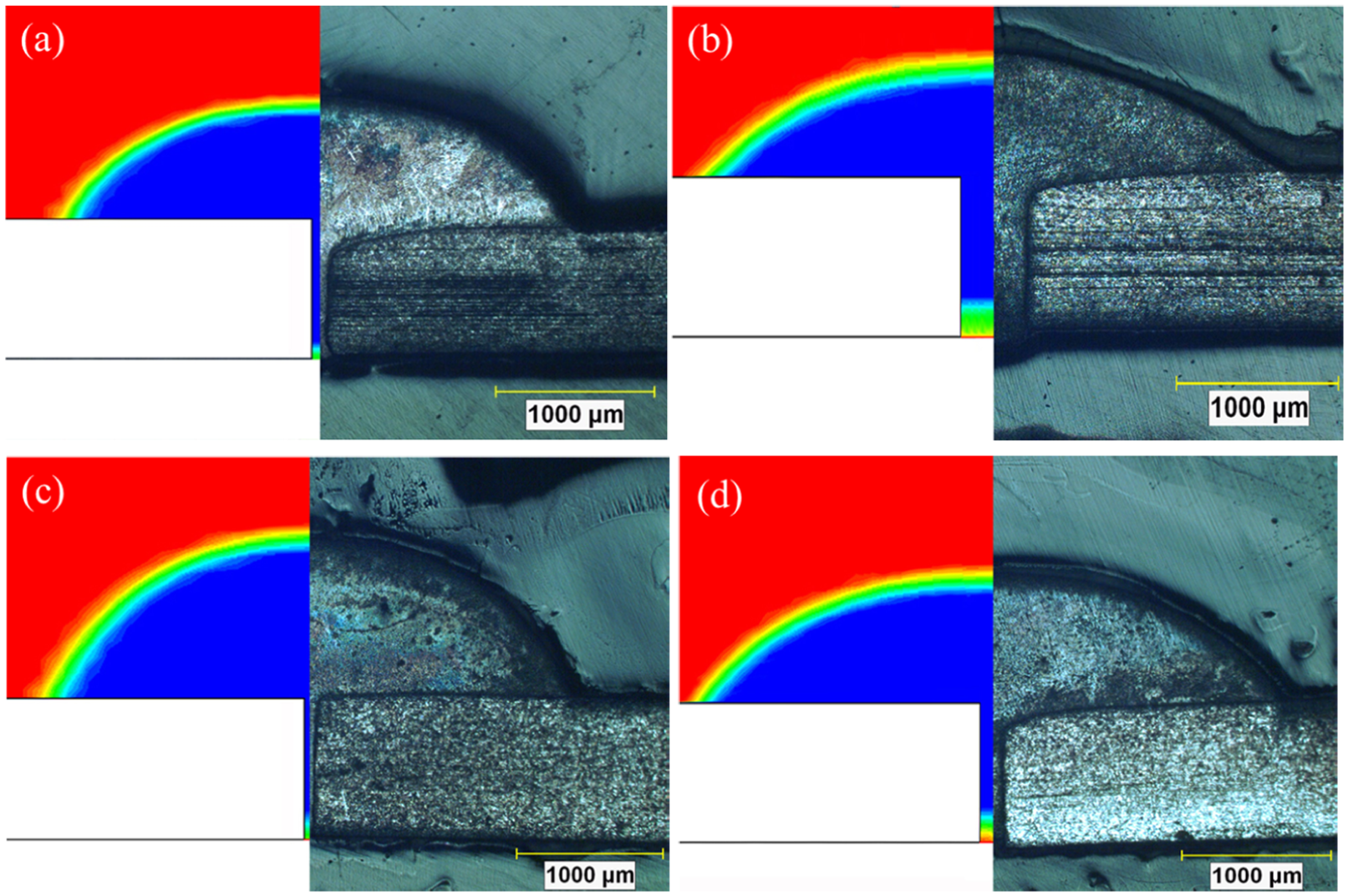
Comparison of the results obtained from the experiment and simulation (a) for 321 SS at 0.08 mm joint clearance, (b) for 321 SS at 0.4 mm joint clearance, (c) for 410 SS at 0.05 mm joint clearance, and (d) for 410 SS at 0.15 mm joint clearance.
Comparison of the results obtained from the experiment and simulation for 321 SS and 410 SS at various joint clearances.
Conclusion
In this study, laser brazing of 321 and 410 stainless steels with AMS 4777 filler metal was performed experimentally and by simulations. This process was performed under a 205.2 W power, 1.7 ms pulse width, 100 Hz pulse frequency, 350 °C preheating, and 1.3 mm/s traveling speed at various joint clearances. A 2D transient model was developed for simulating laser brazing of 321 SS and 410 SS with AMS 4777 filler metal. In this model, the equations of mass conservation, momentum conservation, and energy conservation were solved in FLUENT software for calculating volume fraction and liquid fraction. Important conclusions are summarized below:
The AMS 4777 filler metal shows excellent wettability on SS 321 and 410 SS substrates.
The microstructure of filler metal and laser brazed specimens mainly comprises nickel solid solution (Ni), nickel boride (BNi3), and chromium boride (BCr).
The application of laser brazing process cannot completely avoid the formation of eutectic phases which are very hard and brittle. However, laser brazing is an effective way to prevent the growth of intermetallics at the substrate/filler metal interface.
The average tensile strength value decreases as the joint clearance increases from 0.05 to 0.4 mm. 321 SS and 410 SS laser brazed specimens at 0.05 mm joint clearance demonstrate the maximum joint strength of 480 and 460 MPa, respectively. The high tensile strength of laser brazed specimens is due to less growth of intermetallics at the substrate/filler metal interface.
There is a good agreement between the numerical and experimental results. The results show that this model can predict nearly accurate wetting behavior of AMS 4777 filler metal on 321 SS and 410 SS substrates at any joint clearances. The average error in prediction of spreading width and wetting angle is less than 1.6% and 4%, respectively.
The numerical and experimental results show that the filler metal fills completely the joint gap at all brazing clearances.
Footnotes
Declaration of conflicting interests
The author(s) declared no potential conflicts of interest with respect to the research, authorship, and/or publication of this article.
Funding
The author(s) received no financial support for the research, authorship, and/or publication of this article.