
Abstract
Nowadays, the functionality of products often requires that parts are manufactured with a very small error. The squareness of metrology equipment is an important qualification for the functionality. Traditional methods of measuring squareness of ultra-precision motion stage have many limitations, especially the errors caused by inaccuracy of standard specimens, such as bare L-square and optical pentaprism. And generally, the accuracy of squareness measurement is lower than the accuracy of interior angles of standard specimens. Based on the error separation, this article presents a novel method of squareness measurement with a polygon artifact on the ultra-precision metrology machine. The angles bounded with the guideways and the edges of polygon artifact are measured, and the squareness distraction is achieved by the principle that the sum of internal angles of a convex polygon artifact is (n − 2)π. A squareness metrical experiment is carried out on the profilometer using an optical square brick with the squareness of interior angles at about 0.3° and 2.4″. The results show that the squareness between the X axis and Y axis of the profilometer is approximate, and the accuracy of the squareness is not affected by the value of interior angles. The accurate measurement is much higher than the accuracy of the interior angles of brick. Based on this method and the traditional method, the three terms of squareness are calibrated and improved from 19.71″, 21.37″ and 16.54″ to 3.28″, 7.83″ and 5.88″, respectively.
Introduction
The functionality of products often requires that parts are manufactured with a very small geometric error. High-precision manufacturing with sub-micron error not only needs reliable and flexible production machines 1 but also highly accurate metrology equipment. Among geometric errors, the squareness is significant. The squareness is difficult to analyze and greatly affect the precision of geometric error model, 2 and the squareness accounts for more than 30% of all geometric errors especially on ultra-precision motion stage. 3 The geometric error of motion axis can be measured by laser interferometer for general precision motion stage. 4 But the interferometer cannot be used to measure the squareness of the ultra-precision profilometer, 5 such as the Renishwa XL-80 interferometer. Therefore, some other methods need to be considered.
The commonly used methods for squareness measurement can be divided into three categories. The first method is known as parametric modeling, such as integrated geometric error model6–8 and product of exponential model.9–11 The model can forecast and compensate the geometric errors on the condition that the basic geometric errors are measured, identified and compensated. 12 The basic geometric errors are obtained by the 9-line method, 13 13-line method 14 and step-diagonal measurement method 15 with the interferometer. At the same time, the measurement devices are developed at home and abroad based on this method, such as 3D probe-ball,16,17 ball bar 18 and R-test. 19 The method uses matrices to transform an array of every degrees of freedom (DOFs) at the point of measurement to those at the point of interest. In the case, the level of accuracy of the errors becomes highly dependent on the level of accuracy of the kinematic model as well as the level of the every DOF errors. Because this method belongs to the comprehensive error measurement, the measurement is carried out with the special devices, and the key factors of measurement are the calibration of the devices and the error modeling; obviously, the accuracy of the measurement is lower than the single measurement of squareness.
The second method uses standard specimens. This is most likely the most common, accurate and convenient method. However, it can be expensive and even inaccurate as the measuring range becomes larger because a specimen that exceeds commercially available dimensions should be custom-made and the cost is linked to the level of accuracy required. The principle of this method is given by GB/T 17421.1-1998 General Test Machine. 20 Wang and Sun 21 and Wang 22 measure the squareness of the guideways with the L2 and dial gauges. The squareness of coordinate measuring machine (CMM) was measured by interferometer and the pentagonal prism. 23
The third method is based on the error separation. The basic idea and benefit of this method is that even low-quality specimens can be employed in the measurement because their errors are separated from the error of interest. For this reason, the error-separation method is the most cost-effective method for large-range measuring. Also, the level of achievable accuracy can reach the level of system repeatability if the process is executed well. The error-separation method is known for measuring the straightness of guideways, but is rarely used for measuring the squareness. This method is also known as the reversal method or error-separation technique in the literature. Hocken and Borchardt 24 use this method to measure the squareness; Lieberman 25 first introduced the concept of rotating a specimen in an earlier e-beam lithography system calibration; Ruijl 26 applied an error-separation technique for the straightness calibration of a mirror, and Hume’s angular measuring method 27 is used for squareness measurement. In this article, the methods of Ruijil and Evans et al. 28 are improved and applied for measuring the squareness between the X and Y axes of the profilometer, and the error analysis and simulation are verifying the accuracy and validity of the method.
The error measurement and compensation of computer numerical control (CNC) machine and CMM is the theme of CIRP (International Institute for Production Engineering Research) in 2008. The conferences regard that the error is measured effectively as the important study fields within the foreseeable 10 years. Therefore, the method to improve measurement accuracy is of great practical significance to ultra-precision motion stage.
Principle
In order get the squareness between two axes on a machine, an optical polygon is used. First, the triangular artifact is used to measure the squareness between the X and the Y axes as shown in Figure 1.
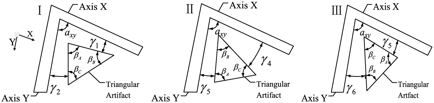
Three positions of the triangular artifact to establish the angle axy between the X and Y axes.
For position I, the angle axy is bounded with axis X and axis Y. The angles βA, γ1 and γ2 satisfy the following relationship

The artifact goes to position II and III after continuously being rotated at an angle, and the following equations can be obtained


The three interior angles meet the following requirement

Summation of equations (1)–(3) and substitution of equation (4) yields
Second, the quadrangular artifact is used to measure the squareness between the X and the Y axes as shown in Figure 2. In position I, the angle axy is bounded with the X and Y axes. The angles βA, γ1 and γ2 satisfy the following relationship

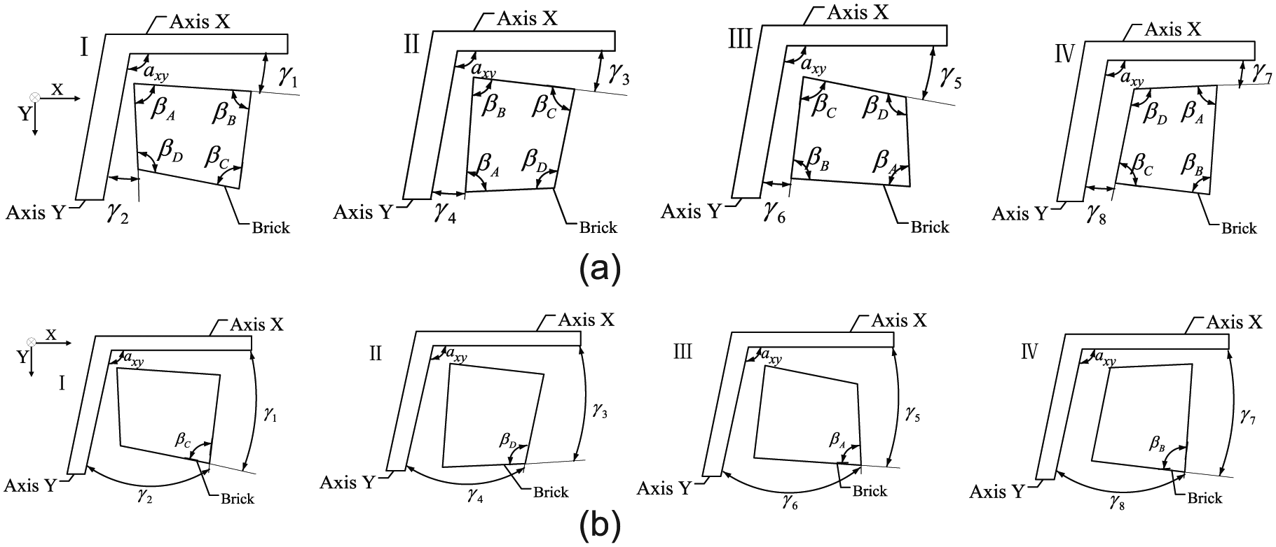
Four positions of the artifact to establish the angle axy between the X and Y axes: (a) first strategy for measuring the angle γi (i = 1–8) with quadrangular artifact. (b) Second strategy for measuring the angle γi (i = 1–8) with quadrangular artifact.
The artifact goes to positions II, III and IV after continuously rotating at an angle of approximately 90°, and the following equations can be obtained


The angles of the artifact meet the following requirement

Summation of equations (6) and (9) and substitution of equation (10) yields
Finally, the optical polygon artifact is used to measure the squareness between the X and the Y axes as shown in Figure 3.
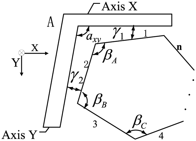
Measuring the angle axy between the X and Y axes with an optical polygon.
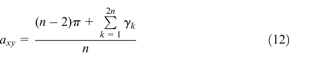
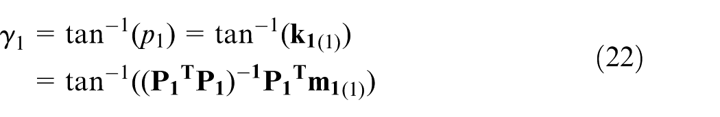
For a polygon at different positions, the relationships among angles βi (i = A, B, C, D) and two angles γi are same as a triangular artifact or a quadrangular artifact. Based on the fact that the sum of the internal angles of a polygon is (n − 2)π degrees, the angle axy between the X and Y axes can be obtained as
The squareness is calculated as

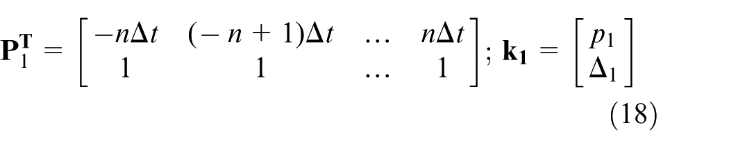
From formula (11), it can be seen that the angles γi (i = 1–8)between the faces and the guideways are measured before getting the squareness axy of X and Y axes. In order to get γi (i = 1–8), the displacement sensors and the corresponding displacement sensors jig are used. For position I, the measurement angle of γ1 and γ2 is shown in Figure 4. Brick angle βA is bounded with brick of peripheral face D and face A, so γ1 is determined by measuring the brick face A. Specifically, for brick face A at any point (x, y) with x = [−n, −n + 1, …, n] and y = [−n, −n + 1, …, n], it is satisfied that

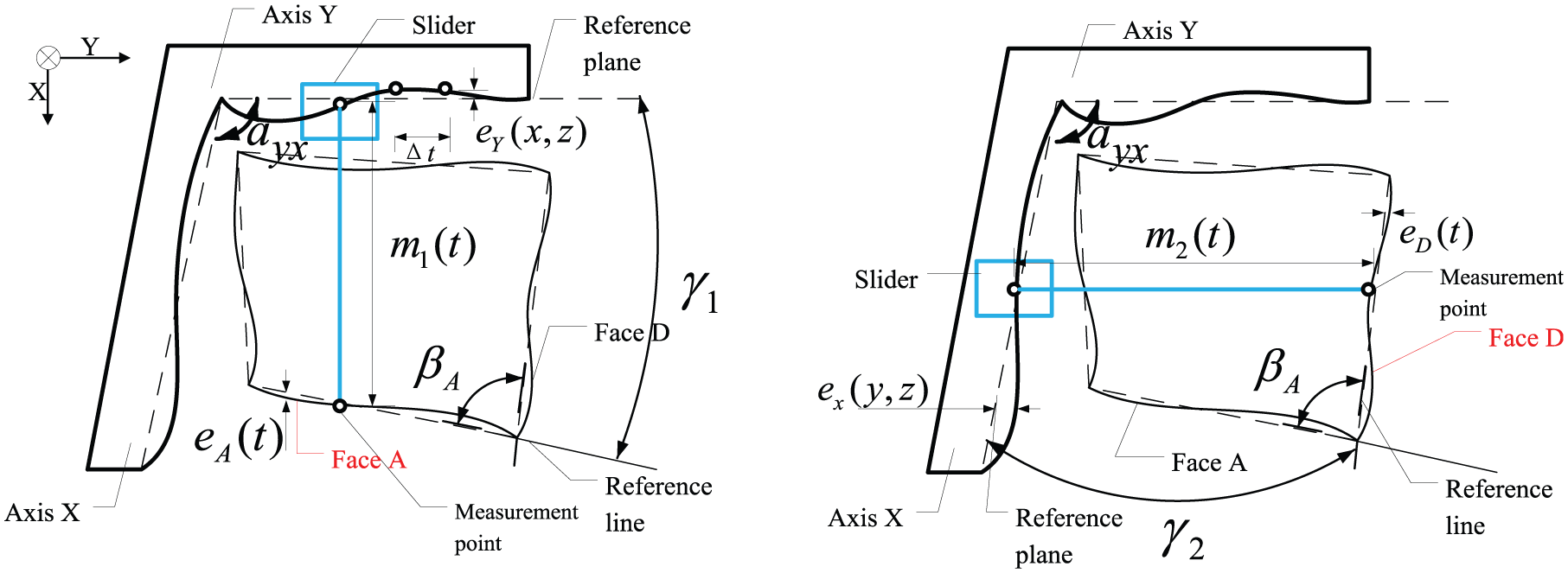
Schematic diagram of the measurement principle in the position I (measuring of brick face A to determine the angle γ1 and face D to determine the angle γ2 for the measurement of the angle axy).
where the straightness deviations of brick face A are denoted by eA(ti); eY(ti)is the flatness deviations; m1(ti)is the distance between the face C and the guideway and measured by the displacement sensor; ti is a step distance value which is the independent variable in the whole measurement process; the wedge between the reference line of the brick face and the reference plane is defined with the parameters p1 and v1. v1 is the unknown variable that makes formula (14) be right and the value of v1 needs not to be calculated. The angel γ1 is determined by p1 according to

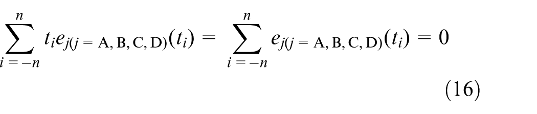
The definition of the reference lines and planes is made less sensitive to random measurement errors by a least squares definition. 29 Furthermore, the solution can be obtained from a linear operation according to a simple matrix equation. A useful least squares definition is
Therefore, all the points along the face D reference line measured every Δt are expressed by matrix as

where
Multiplying matrix equation (17) with

The matrix

Then, formula (19) can be written as

The angle γ1 can be calculated by the first element p1 in column matrix
The other γi are obtained as same as the γ1. At the same time, the symbol of every angle γi needs to be considered. According to the definition given in Figure 1, the sign of two adjacent γi is different. Finally, the angle axy is obtained from formula (11).
Experiment
Experiment equipment
The experiment setup is shown in Figure 5. The two sensors are the STIL CL2, and the controller of the sensors was the Prima STIL Initial. The measuring range is 400 µm; maximum linearity error is 0.023 µm. The X and Y axes straightness of the profilometer is 0.1 μm/250 mm.
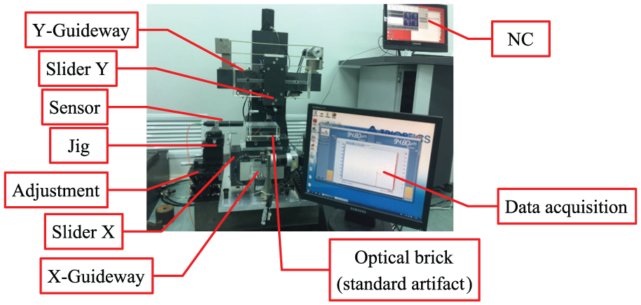
Experiment setup for the X and Y axes squareness.
The optical brick
In order to measure the squareness between the X and Y axes, a brick with four faces is used based on the error separation, and one with two faces is used based on the standard specimens. Figure 6 shows the definitions of the four angles of the brick and six faces. The original accuracy of the brick was not very well as listed in Table 1. The accuracy of four faces of brick and the values of the four angles are shown in Figure 7 and Table 1, respectively, and the face accuracy is measured by digital wave-front laser interferometer phase shift Zygo GPI-XP/D; the angle is obtained by the German TRIOPTICS precision goniometer PrismMaster MOT. The values of the angles of the brick are improved by modifying the face shape with the computer-controlled optical surfacing (CCOS) and magnetorheological finishing (MRF). Therefore, the squareness errors of angles of brick are improved to arcsecond level and to be a standard specimen. But the improvement of the accuracy of the brick is costly through the process of the modification.
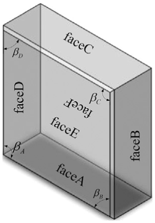
Definition of angles and faces.
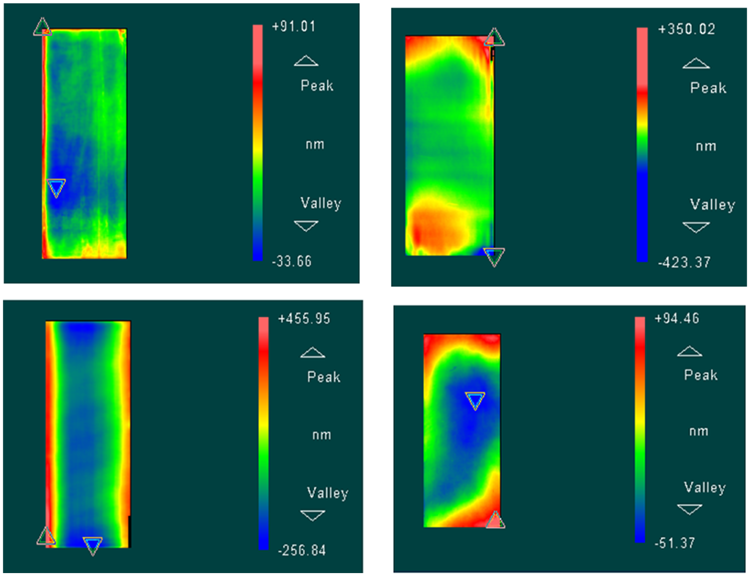
Original accuracy of the four faces of brick (face A, face B, face C and face D, from left to right).
Values of the four angles of the brick.
Experiment data and results
The squareness between the X and Y axes based on the error separation
In order to decrease the random errors of the experiment in the experimental process, the sampling frequency is set to 2000 Hz and the sampling time is set to 10 s at each measuring point, and then, the 20,000 sampling datum is averaged as the value of the point. As the range of the brick is 145 mm and the Δt is 10 mm, the number of the measuring point is 13 on every face of the brick. From formula (18), the number of the point is odd. One of the experimental data is shown in Figure 8.
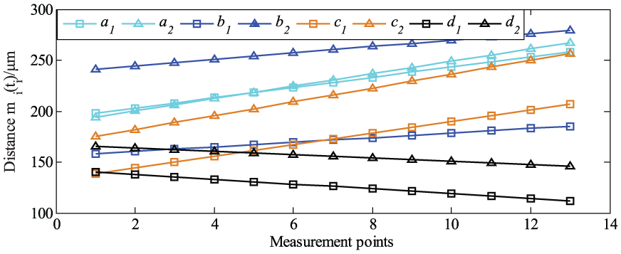
One of the five groups of experimental data.
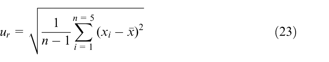
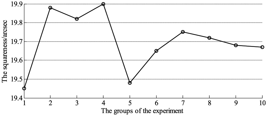
The five groups of experimental data determine the angles γi, and the results of angles γi calculated by program are listed in Table 2. The squareness between X and Y axes is calculated by formula (6) and shown in Figure 9. Hence, the squareness between X and the Y axes is 19.71 arcsec, and the repeated measurement accuracy ur is determined by formula (23) and reaches 0.22 arcsec
Three groups of experimental results of angles γi.
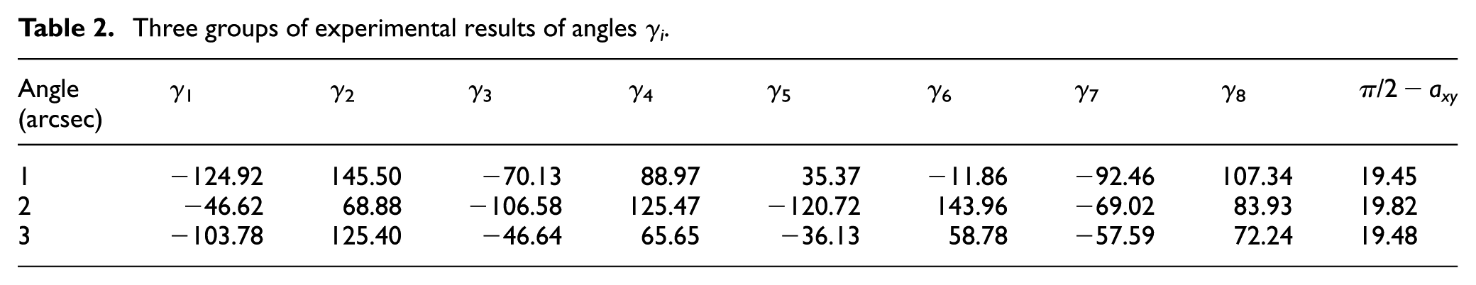
Results of squareness (π/2 − axy) based on the separation.
The alteration of the four brick angles’ effect on the measurement
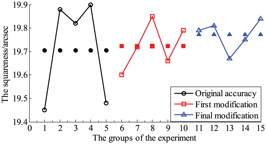
The experiment that the accuracy is not affected by the accuracy of the brick is carried out. Table 1 shows the alteration of the four brick angels. The squareness between X and Y axes is measured under the three kinds of accuracy of brick listed in Table 1. The results of the squareness with the alteration of the four brick angles are shown in Figure 10. The results of the three measurements are 19.72, 19.77 and 19.71 arcsec; therefore, the accuracy of the measurement based on the error separation is not limited by the accuracy of the brick.
Results of the squareness with the alteration of the four brick angles.
The squareness between the X and Y axes based on the standard specimen
The principle of this method is given by GB/T 17421.1-1998 General Test Machine as shown in Figure 10. The four angles of brick have high accuracy after modifying as listed in Table 1, so the brick can play the standard specimen part to measure the squareness between the X and Y axes. The experiment equipment is the same as the method of error separation. Figure 10 is one of group of the straightness of X and Y axes. The experimental data are dealt with the least squares fit and filter as shown in Figure 11, and the straightness error is obtained. Finally, the squareness is calculated according to the relationship between the guideways and the angle of brick. Figure 12 shows the different results between the method of error separation and the method of standard specimen.
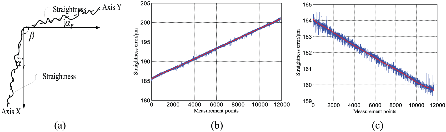
One of the groups of the straightness of X and Y axes: (a) principle of standard specimen, (b) straightness of X axis with tilt and (c) straightness of Y axis with tilt.
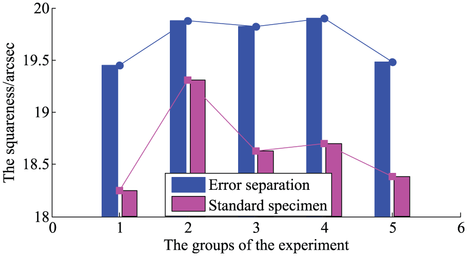
Difference of the squareness results between the two methods.
From Figure 12, it can be seen that the squareness result of standard specimen is 1.06 arcsec less than that of error separation. The result of standard specimen can basically prove that the squareness of the error separation is right, but cannot figure out which one is the higher precision.
The angle of the brick is obtained by the German TRIOPTICS precision goniometer PrismMaster MOT and the error of the equipment is 0.5 arcsec actually. The accuracy of measurement result based on the standard specimen is ensured with the error at least 0.5 arcsec. Although the method of standard specimen can measure the squareness of the profilometer, the accuracy is not very high and the brick needs costly work to be a standard specimen from section “The optical brick.” According to error analysis, the measurement error based on error separation is 0.06 arcsec. The result shows that error of the method based on error separation is much smaller under normal conditions than the standard specimen.
The calibration of the profilometer squareness
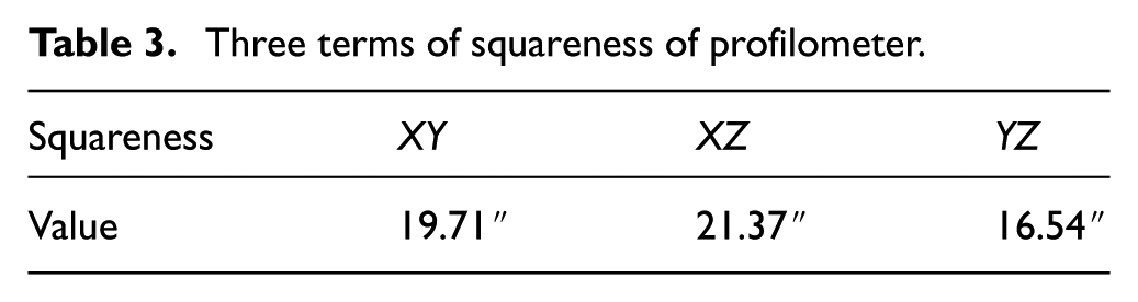
The three terms of squareness are obtained by the same method based on error separation and the results are listed in Table 3.
Three terms of squareness of profilometer.
The order of calibrating the squareness of the profilometer is calibrating the XY squareness first, calibrating the XZ squareness second and the YZ squareness finally. The order of the calibration is so important that the three results of calibration will not affect each other. The results of calibration are listed in Table 4.
Three terms of squareness of profilometer after calibration.
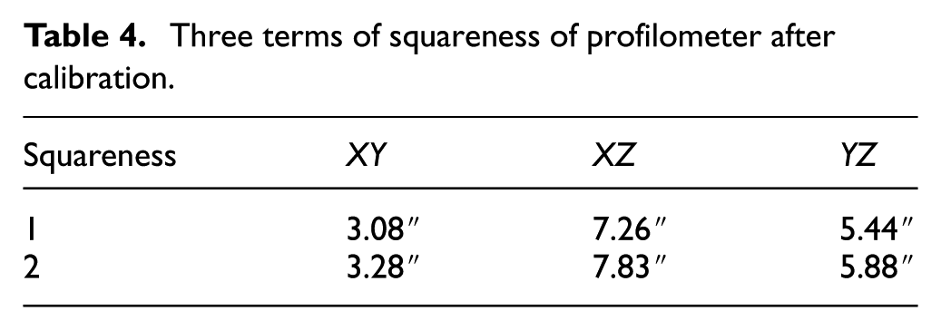
In Table 4, the first value is measured based on standard specimen and the second value is based on the error separation. The results are measured with the method based on the error separation, but in the process of calibration, the method based on standard specimen is used to calibrate the squareness since the squareness is obtained more easily but lower accurately than the error-separation method. As shown in Figure 13, the angle error (0.4654 μm/144.5 mm) between the X axis and the brick is 0.66″ and the other (1.7229 μm/146.6 mm) between the Y axis and the brick is 2.42″. So, the squareness between X and Y axes is 3.08″ based on standard specimen after calibration. As listed in Table 4, the XY squareness is 3.28″ on the error separation and there are 0.20″ error between the two methods. From the results shown in Figure 12, the error is natural.
Straightness of X and Y axes with tilt: (a) straightness of X axis with tilt (error: 0.4654 μm/144.5 mm or 0.66″) and (b) straightness of Y axis with tilt (error: 1.7229 μm/146.6 mm or 2.42″).
The sensor used in measuring the XZ and YZ squareness is different from measuring the XY squareness as shown in Figure 14. The sensor of MarH is used because the measuring range of Z axis is 50 mm.
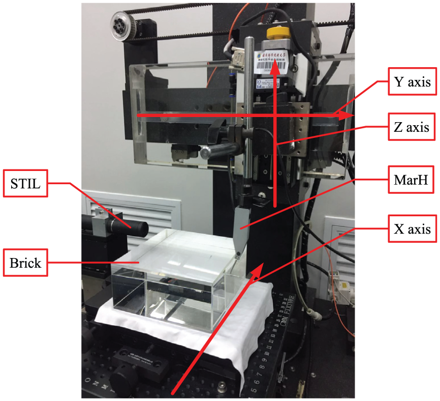
YZ squareness measurement with a sensor of STIL and another of MarH.
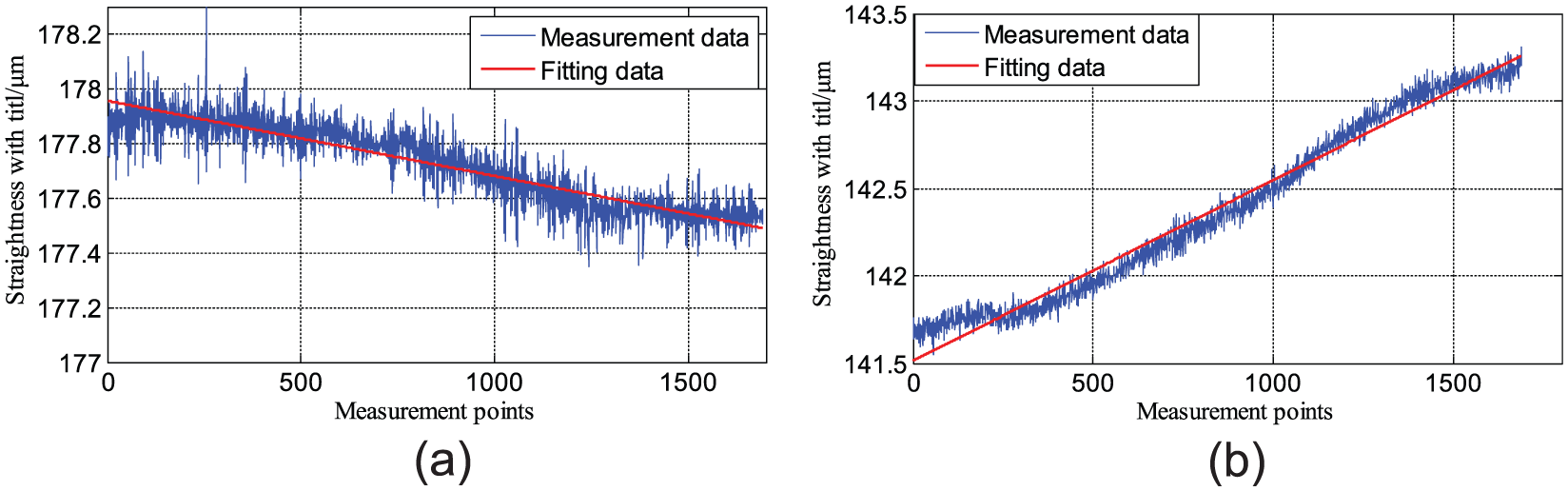
As shown in Figure 15(a), the red line named “average data” is the straightness with tilt of Z axis, and the line is obtained from Dongmin et al.; 30 therefore, the angle error (1.28 μm/48.72 mm) between the Z axis and the brick is 5.42″, and the other (0.0118 μm/146.6 mm) between the Y and the brick is 0.02″. So, the squareness between the Z and Y axes is 5.44″ based on standard specimen after calibration. But, however, the YZ squareness is 5.88″ with the method based on error separation.
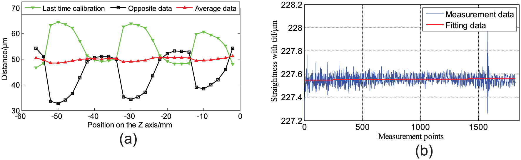
Straightness of Y and Z axes with tilt: (a) straightness of Z axis with tilt (error: 1.28 μm/48.72 mm or 5.42″) and (b) straightness of Y axis with tilt (error: 0.0118 μm/146.6 mm or 0.02″).
As shown in Figure 16, the process of calibration is obtained, and the result shows that the tilt of straightness of Z axis is decreased. Similarly, the XZ squareness is obtained with the result of 7.26″ based on the standard specimen and 7.83″ based on the error separation.
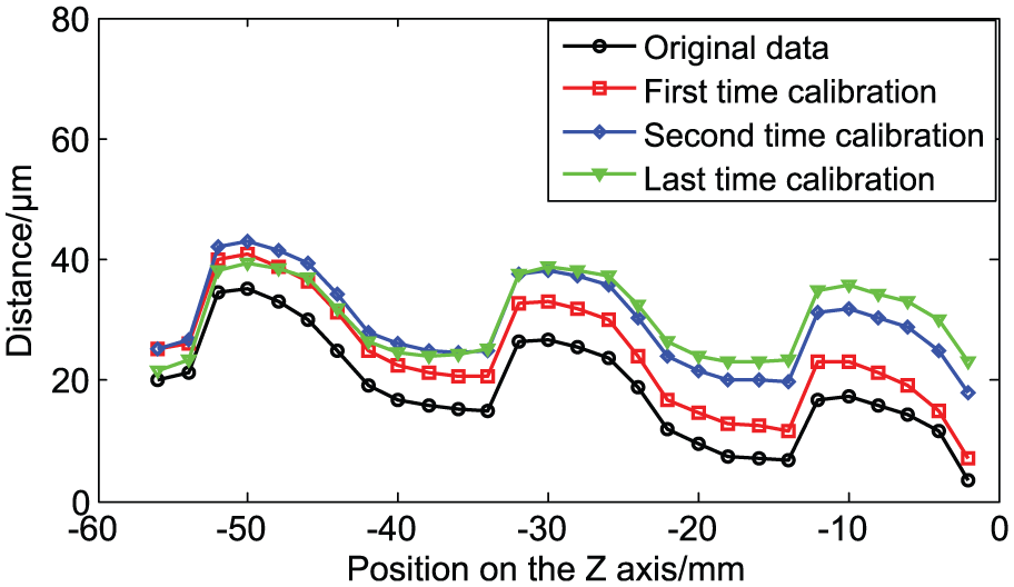
Process of calibration of straightness of Z axis.
Conclusion
The method of squareness measurement based on the error separation is studied and analyzed in detail. And the squareness of the ultra-precision machine is measured and calibrated. The conclusions can be drawn as follows:
The squareness between the X and Y axes of the profilometer is measured with the interior angles at about 0.3° and 2.4″. The results show that the squareness between the X and Y axes of the profilometer is approximate, and the accuracy of the squareness is not affected by the value of interior angles.
Compared with the traditional method, the accuracy of the measurement is not affected by the accuracy of the standard specimen. The accurate measurement is much higher than the accuracy of the interior angles of brick.
Based on this method and the traditional method, the three terms of squareness are calibrated and improved from 19.71″, 21.37″ and 16.54″ to 3.28″, 7.83″ and 5.88″, respectively.
Footnotes
Declaration of conflicting interests
The author(s) declared no potential conflicts of interest with respect to the research, authorship and/or publication of this article.
Funding
The author(s) disclosed receipt of the following financial support for the research, authorship, and/or publication of this article: This research has been supported by the New Century Excellent Talents Scheme (NCET-12-0144) and the National Natural Science Fund (No. 51005259).