
Abstract
Recent developments in small hard components, such as those used in medical devices, have led to more stringent requirements of the machining process. Many high-precision technologies have been developed to machine such components. The tool clamp is an important part of a machine tool, and collet chuck tool clamp systems are widely used for small spindles. However, use of small precision tool clamps with commercial spindle chucks is limited by the inherent complexity of the operating mechanism. To address this, we describe a shape-memory alloy tool clamp that has a simple structure and can provide sufficient tool-clamping force. We describe the deformation of the tool clamp analytically, where a surface load is placed on an arbitrary location on the tool clamp via a shape-memory alloy ring. We used a superposition method to predict the deflection of the tool clamp, which could be done quickly because we did not require iterative calculations. The simulation results are compared with experimental measurements of the deflection.
Introduction
Small precision parts, such as those used in medical implants and mobile devices, have seen much recent development. The market for high-precision miniature machine tools has grown to meet the demand for components used in high-tech industries. As machine tools have become smaller, many key components have been developed.1–4 The tapered collet chuck is widely used for small-scale machine tools. However, the complexity of the device results in accumulated errors and hence poor clamping accuracy, and the rotational speed is limited by the inertia of the additional parts. 5
Tool-clamping devices that use shape-memory alloy (SMA) rings can address these shortcomings. 6 SMAs have been applied to various clamping mechanisms, such as fractured bone, 7 tube couplings, 8 microelectromechanical (MEMS) devices, 9 and clamping devices. 10 These applications exploit the characteristic that the shape is restored at room temperature. An SMA tool clamp exploits the restoring forces between the SMA ring and the tool clamp, which result in a deformation of the SMA ring and hence a deflection of the tool clamp. The dimensions of the interference fit between the SMA ring and clamp are critical and because this mechanism requires micron-scale tolerance, it is not straightforward to clamp and unclamp the tool successfully. The tool clamp is particularly prone to failure, so careful design is required, typically involving several iterations. To reduce the workload associated with this process, it is important to consider the initial reference dimensions and specifically to predict the deformation of the tool clamp. Formulating an equation describing the deformation of the SMA ring and tool clamp makes it possible to investigate whether clamping will occur.
Lee et al. 5 formulated a deflection equation that uses an iterative method when the SMA ring is placed in a specific location. However, the calculation of the equation is time-consuming, and there are limits to where the ring can be located. In particular, a large number of iterations under similar conditions are needed to optimize design parameters. By shortening the computation time for one simulation, the total time can be dramatically reduced. Therefore, there is need for a more efficient method that does not use repetitive calculations. This article presents a superposition method that can be used to predict the deflection of a tool clamp directly. This approach allows for a reduction of time in the design phase by eliminating iterative calculations. Thus, even if the ring is located at an arbitrary position, this simulation method can calculate the deformation curve in a single iteration. The SMA tool clamp simulation data were verified by comparison with experimental measurements of a fabricated SMA tool clamp. The next sections describe the configuration of the SMA tool-clamping device and provide a set of equations to predict the deflection of the tool clamp. The maximum calculated deflection is then compared with the experimental results.
Configuration of the SMA clamp
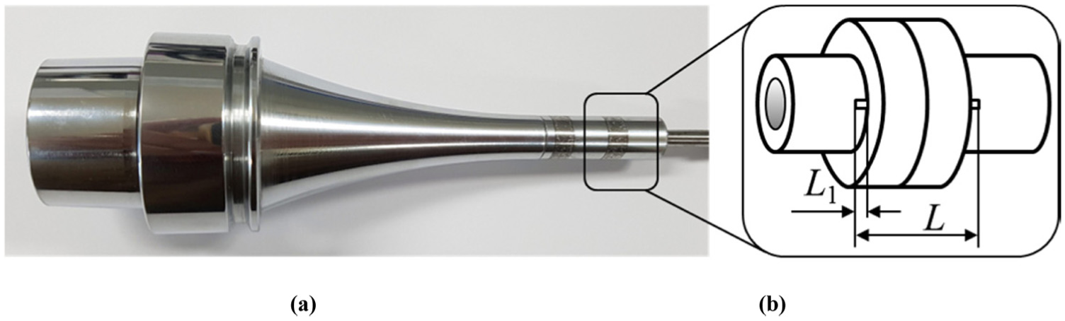
The SMA clamping device was composed of an SMA ring and a tool clamp (Figure 1). The SMA ring had an interference fit with the outside of the tool clamp. The internal diameter of the SMA ring and the external diameter of the tool clamp were determined considering the fit tolerance of the tool shank.
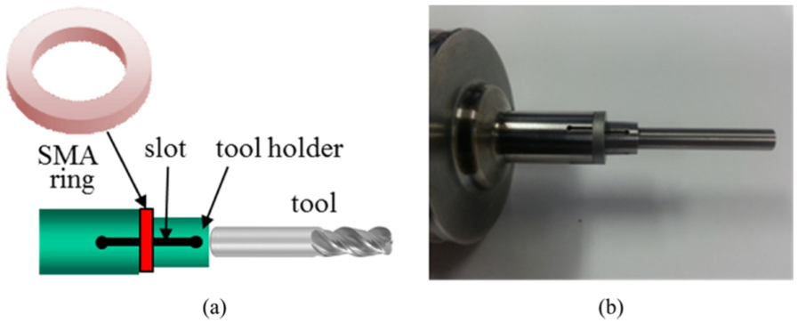
(a) Configuration of a shape-memory alloy (SMA) tool clamp and (b) a photograph of the manufactured device.
Our design is based on the interference fit between the SMA ring and the clamp. When the SMA ring is heated to room temperature, Young’s modulus increases. 11 As the internal size of the tool clamp decreases, the resulting strain holds the tool. Following cooling, Young’s modulus of the SMA ring decreases, enabling unclamping of the tool. The tool recovers to its original size via an inherent elastic force. The internal diameter increases, and the tool can be unclamped. The key to this technology is ensuring that the diameter of the tool clamp is larger than the diameter of the tool at low temperatures and that the tool clamp is smaller than the tool diameter at room temperature. As an SMA tool clamp uses these characteristics; it can have a simple structure compared with a conventional collet chuck 5 (Figure 2).
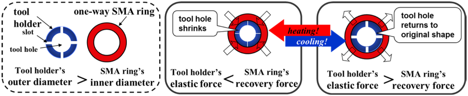
Schematic diagram showing the clamping and unclamping processes with the SMA tool clamp.
Analysis of deflection of the tool clamp
To predict the deformation of the tool clamp, the tool clamp can be considered to be a beam that is clamped at both ends. The distributed force, qc, acts in the central region of the beam, and results from the interference fit between the SMA ring and tool clamp. Using a force and moment equilibrium approach, together with displacement and angle relations, the governing equations can be formulated.
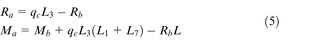
The calculation of the tool clamp shrinkage can be described as a beam deflection problem, where each end is fixed, and a distributed force is applied at an arbitrary location along the beam, as shown in Figure 3. The total length is L, and the coordinates start from point A. The distributed force qc is applied along a length of the beam L3, starting at point D. The separation between points A and C is L1. A reaction force Ra and a reaction moment Ma occur at support point A, and a reaction force Rb and reaction moment Mb occur at support point B at the other end of the beam.
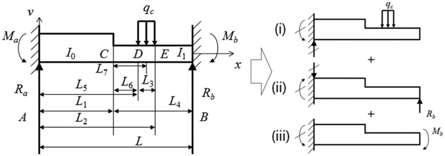
The three beam configurations considered in the superposition method.
We considered three cases and obtained the deflection curve for each case. The three curves were then superposed. Each case can be divided by two segments according to the moment of inertia, the thickness, and the external force. The displacements and the gradient are continuous across point C. Furthermore, the displacements and the gradients are zero at both ends; therefore, A and B are treated as fixed–fixed boundaries.
First, the deflection vL and gradient
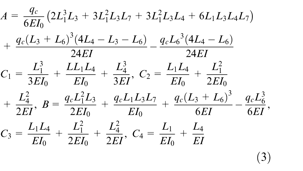
The shear force Vi (where i = 1, 2, or 3) and the bending moment Mi (where i = 1, 2, or 3) at point C can be calculated from the distributed force qc, the reaction force Rb, and the reaction moment Mb. 12 The deflection δi and angle θi at point C can be calculated from the shear force and bending moment, as listed in Figure 4.
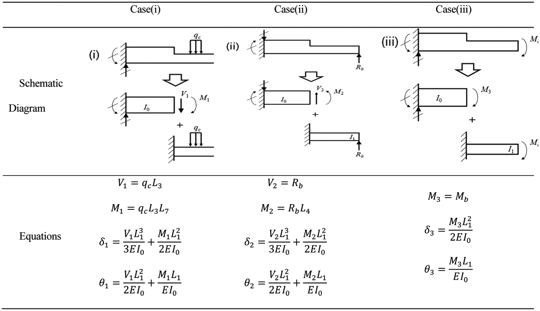
Boundary conditions and governing equations for beam deflection. 12
The deflection from L2 to L can be calculated by superposing these three sets of curvatures, 12 that is
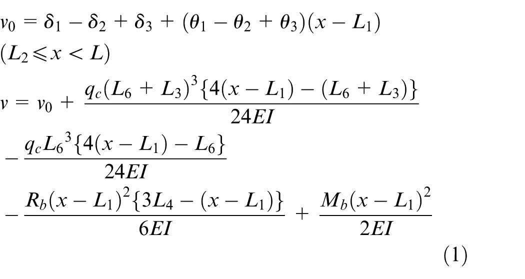
The deflection vL and gradient
where
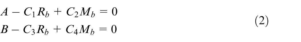
This allows us to calculate Rb and Mb, that is
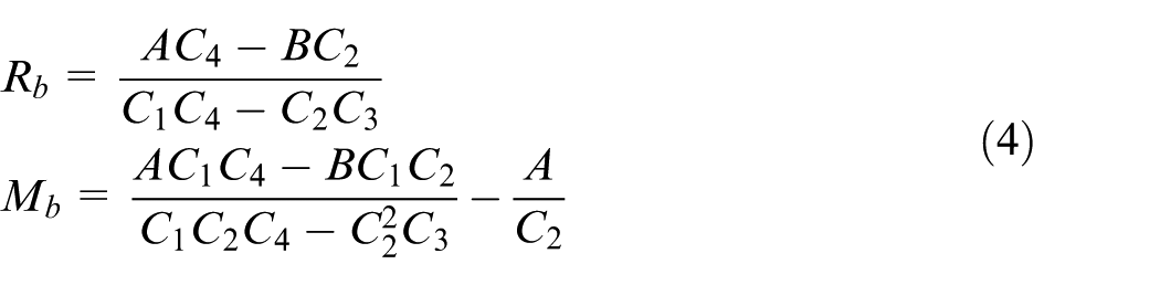
From the force and moment equilibrium conditions (equation (4)), we have
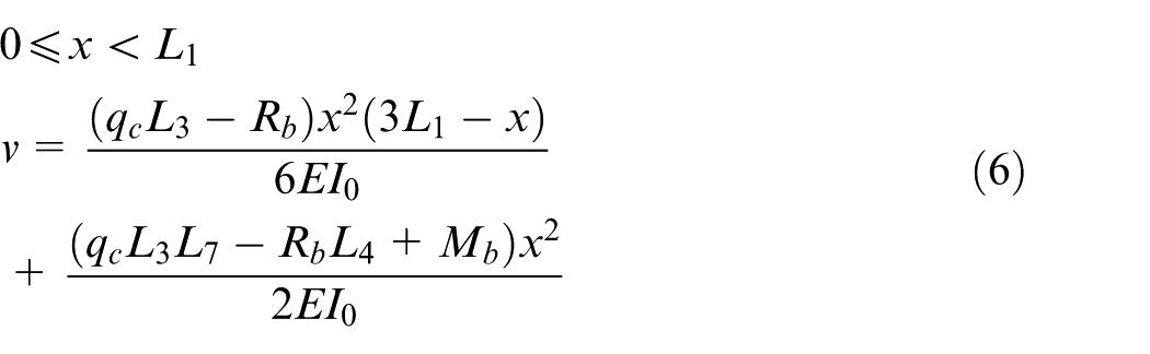
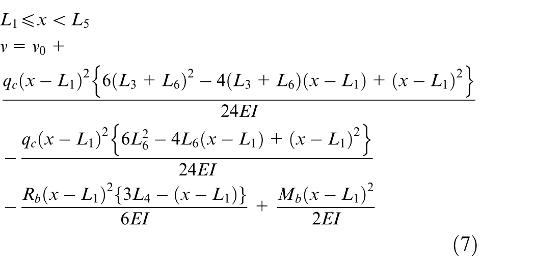
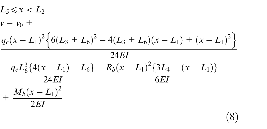
The deflection v at each segment is then as follows 12
We compared the simulation time of the case based on the values in Table 1 using a conventional method 5 and the superposition methodology, performing three simulations for each case and comparing the average time. While the case using the conventional iterative method requires 3629 ms, the superposition method takes 1 ms. This had the effect of reducing the time by roughly 3500 times. This result confirms that the superposition method is very efficient.
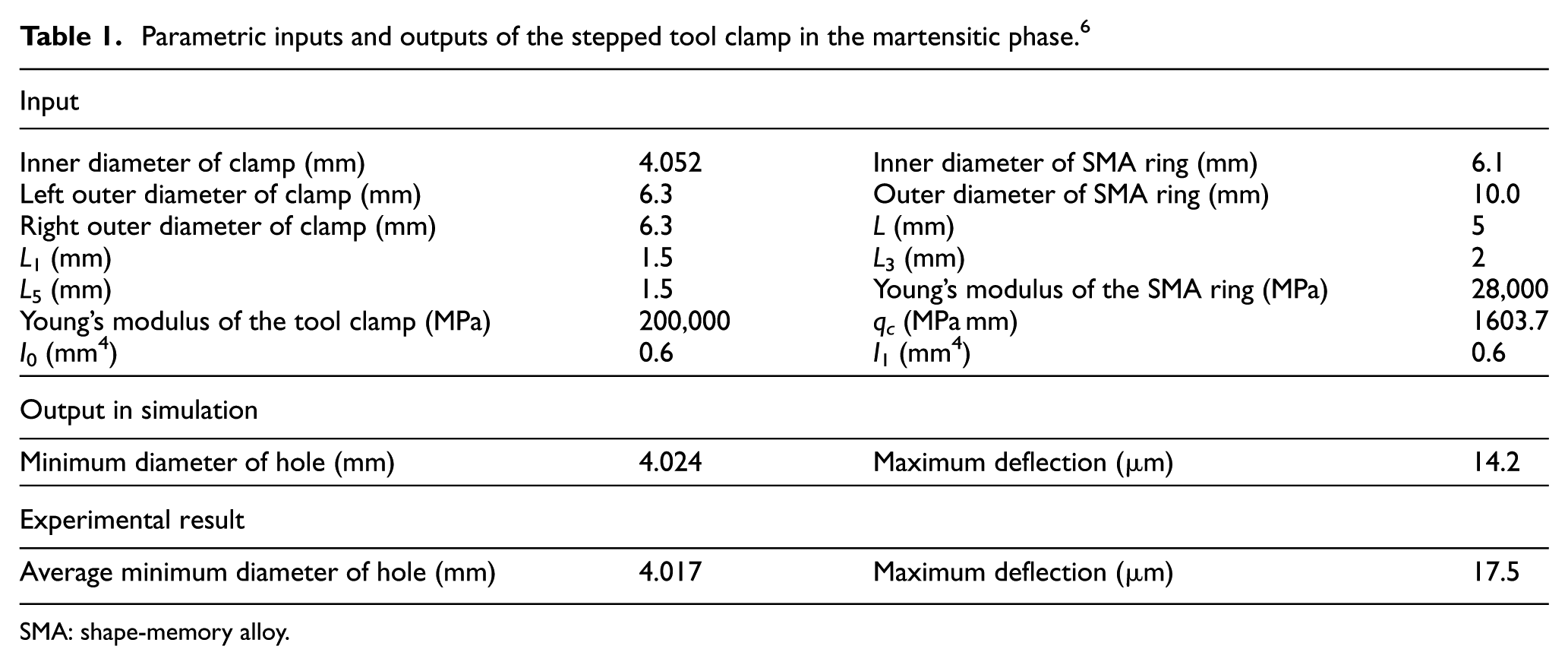
Parametric inputs and outputs of the stepped tool clamp in the martensitic phase. 6
SMA: shape-memory alloy.
Experimental verification
Experiment with single ring
To verify the equations described above, the radial deformation of the SMA tool clamp was measured at different temperatures. To verify the deflection of the tool clamp, it is necessary to measure the internal diameter of the SMA ring in both the martensitic and austenitic phases. It is important to measure the minimum diameter to determine whether the tool can be clamped in the austenitic phase and unclamped in the martensitic phase. First, the maximum change in the internal diameter of the tool clamp was measured in the austenitic phase. Clamping is facilitated when the internal diameter of the tool clamp becomes smaller than the diameter of the tool. The internal diameter of the tool clamp was also measured in the martensitic phase. Unclamping will occur when the internal diameter of the tool clamp exceeds the diameter of the tool.
Figure 5 shows the experimental arrangement used for the measurements. The radial deformation of the interior of the tool clamp was measured using a bore gauge, which had a resolution of 1 µm and could measure the internal diameter in the range 3.7–7.3 mm. The temperature of the SMA ring was measured using a thermocouple. The diameter was measured at 30ºC and at −40ºC. Each experiment was repeated three times, and the data were averaged at each temperature.
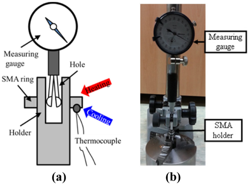
(a) Photograph of the experimental apparatus (Mitutoyo Corp. 526-152; graduations: 0.001 mm, repeatability: 0.002 mm) and (b) schematic of the measuring device.
An SMA tool clamp was designed and fabricated to verify the simulation model. The SMA clamp was a stepped design and was designed for a commercial tool with a diameter of 4 mm. The cylindrical clamp had the same outer diameters (i.e. Dh0 = 6.3 mm; Dh1 = 6.3 mm), as shown in Figure 6. The clamp was hollow and the internal diameter (dh) was 4.1 mm. There were 5-mm-long slots in the longitudinal direction. The internal and external diameters of the ring were 6.1 and 10 mm, respectively, and the ring was 2-mm thick. The distributed force qc was determined as described in Shin et al., 4 and terms I0 and I1 were calculated as described in the study of Beer and Johnston. 13
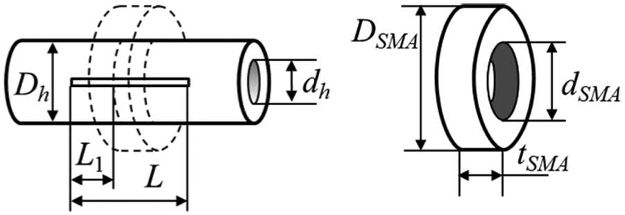
Main dimensions of the tool clamp and SMA ring.
The measured results show that the simulation results are similar to the experimental results. Table 1 shows the parametric inputs of the SMA tool clamp in the martensitic phase. The maximum predicted deflection of the SMA clamp was νmax = 14 μm. As the shrinkage occurred on all sides of the clamp, the internal diameter was reduced by 28 µm. The initial diameter of the SMA clamp was 4.052 mm; it follows that the predicted diameter in the martensitic phase was 4.024 mm. From the experimental measurements, we found that the average diameter in the martensitic phase was 4.017 mm. Therefore, the experimental and simulated results agreed to within 18.9%.
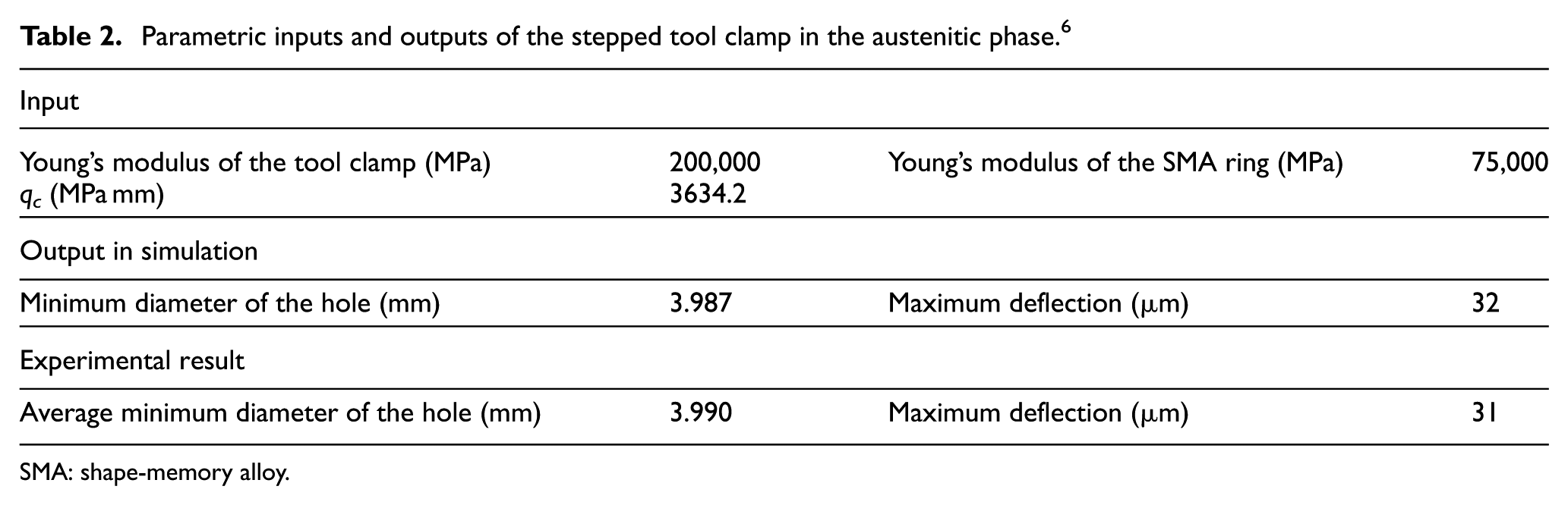
In the austenitic phase, the maximum deflection of the SMA tool clamp was νmax = 32 µm in the simulation, and the maximum value was 31 μm in the experiments. Table 2 shows the parametric inputs and the results in the austenitic phase. The deflection of the jaws at the end resulted in a 64-µm change in the internal diameter of the tool clamp. The initial diameter of the SMA clamp was 4.052 mm; in the simulation, the diameter was 4.987 mm, and in the experiments, the average internal diameter was 4.990 mm in the austenitic phase. Therefore, the simulated and experimental results agreed to within 4.2%. The error source is determined by linearization of the calculation and measurement error of the gauges.
Parametric inputs and outputs of the stepped tool clamp in the austenitic phase. 6
SMA: shape-memory alloy.
The error between the simulated and measured data was slightly larger in the martensitic phase than in the austenitic phase. In practice, an 18.9% error margin does not affect the unclamping success because the deflection reached 35 µm in the experiment. Therefore, the simulated results can be used to design tool clamps of various sizes. A tool with a diameter in the range 3.990–4.017 mm can be clamped and unclamped using the tool clamp described here.
Experimental verification with superposition case
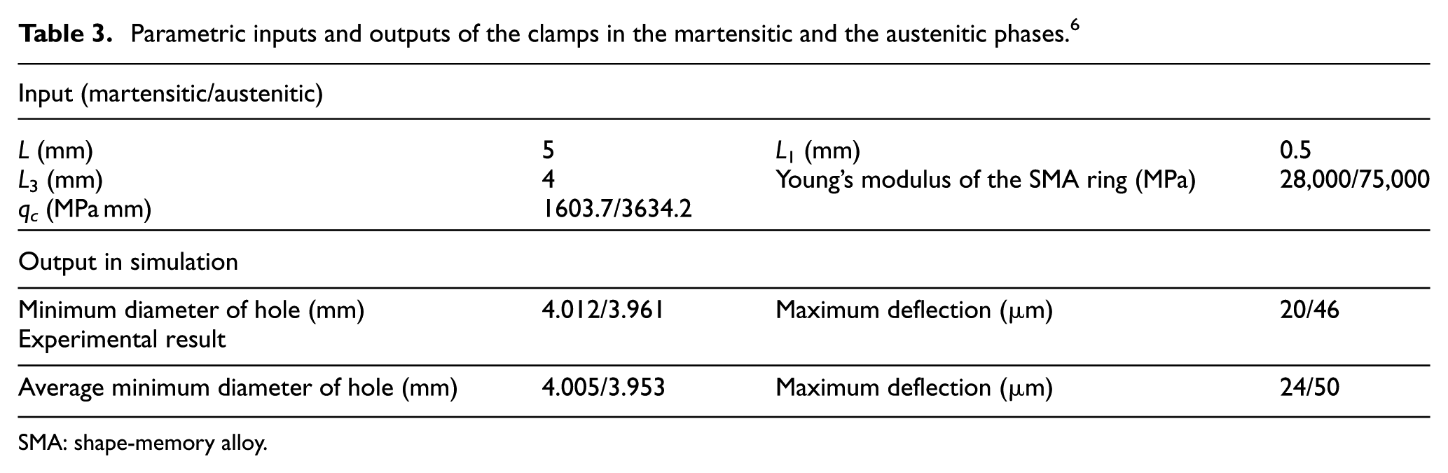
The experimental results were compared with the simulation results after performing experiments when two rings were installed. Each ring had a thickness of 2 mm, so the total thickness was 4 mm. The distributed force qc was determined as described in the study of Shin et al., 4 and the terms I0 and I1 were calculated as described in the study of Beer and Johnston, 13 as in the previous section. The two rings are placed at a designated point so that they are symmetrical to the slot in Figure 7. Table 3 shows the parametric inputs of the SMA tool clamp in both phases. The maximum predicted deflection of the SMA clamp was νmax = 20 μm in the martensitic phase. As the shrinkage occurred on all sides of the clamp, the internal diameter would be reduced by 40 µm. The initial diameter of the SMA clamp was 4.052 mm; it follows that the predicted diameter in the martensitic phase was 4.012 mm. From the experimental measurements, we found that the minimum diameter in the martensitic phase was 4.005 mm. Therefore, the experimental and simulated results were within 14.5%.
Schematic diagram of the developed SMA tool clamp.
Parametric inputs and outputs of the clamps in the martensitic and the austenitic phases. 6
SMA: shape-memory alloy.
The maximum predicted deflection of the SMA clamp was νmax = 46 μm in the austenitic phase. Consequently, the internal diameter was reduced by 91 µm. The initial diameter of the SMA clamp was 4.052 mm; it follows that the predicted diameter in the austenitic phase was 3.961 mm. From the experimental measurements, we found that the minimum diameter in the austenitic phase was 3.953 mm. The experimental and simulated results were within 7.8%. This result is shown in Figure 8.
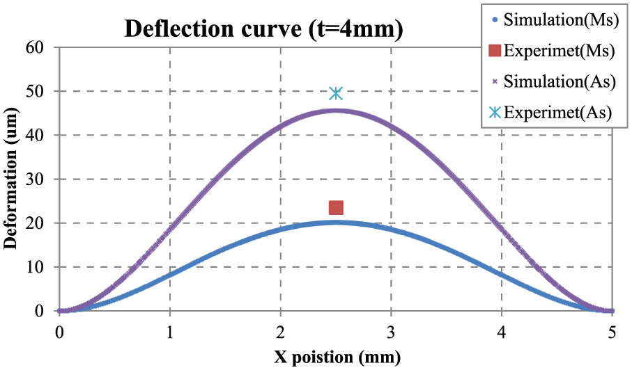
Deflection curve of the SMA tool clamp.
Conclusion
We developed a method for calculating the deflection curves of an SMA tool clamp, which we used as part of the design process. To obtain the deflection curve of the tool clamp, the governing equations were solved using the superposition method. Simulations were carried out using these solutions, and the resulting maximum deflections were compared with experimental measurements. In the case of one ring, we found that the agreement between the simulated and measured data was within 13.3% in the martensitic phase and within 27.5% in the austenitic phase. In the case of two rings, the agreement was 14.5% in the martensitic phase and within 7.8% in the austenitic phase. The tool clamp was able to clamp and unclamp the cylindrical workpiece successfully, and the initial displacement of the tool clamp was predicted using the deflection curves obtained from the superposition method.
As future work, we will conduct a study to optimize the design parameters using this superposition method.
Footnotes
Appendix 1
Declaration of conflicting interests
The author(s) declared no potential conflicts of interest with respect to the research, authorship, and/or publication of this article.
Funding
The author(s) received no financial support for the research, authorship, and/or publication of this article.