
Abstract
Large-dimension welded joints are widely used in shipyards and oilfields. These joints typically have thick and nonuniform welding grooves, thus requiring multi-pass welding processes and tens of hours to complete. Although the development of robotic welding systems can shorten the welding time, it is important to have a detailed plan of the entire process before welding starts. Welding pass planning is crucial for the subsequent robot trajectory generation and provides the welding sequence in a deep groove and the welding parameters of every pass. A knowledge database is used in this research to obtain the relationship between the bead geometry and the welding parameters. A layer-by-layer welding pass planning scheme is proposed to address the nonuniform groove geometry, and an optimization method is proposed with the objective to maximize the section area of the weld bead, so that the number of passes can be minimized. The planning results show that the optimization method is able to provide feasible passes and welding parameters for every pass.
Introduction
In shipyards and oilfields, it is common to have large-dimension welded joints consisting of thick plates or pipes. Single-pass welding cannot fill the deep grooves of these joints. Correspondingly, multi-pass welding becomes necessary, and manual methods are usually used. The process of manual methods includes preheating, flame cutting, grinding, arc welding, post-heating, polishing and so on. In order to achieve good quality, the entire process poses high requirements on the welding technicians, and it is difficult to achieve high productivity. With the advancement of robotic welding processes, high accuracy and high efficiency have become possible for the welding of deep grooves.
For robotic welding systems, welding task planning is important to welding quality and efficiency. Hence, it has drawn many researchers’ attention.1–4 Offline robot programming methods are still the most prevalent for robot welding task planning and simulation prior to converting the welding passes into robot welding paths. Augmented reality (AR)–based robot programming methods5–7 improve offline programming by allowing adequate human intervention through which the task can be planned, modified, simulated and visualized in an augmented environment.
Welding of deep grooves requires multiple passes to fill up the groove section. To realize automatic welding solutions, precise pass planning is critical to provide welding sequence and route and subsequently robotic trajectory. Park and An 8 reported that a welding sequence can have a significant effect on welding distortion, which would subsequently affect the welding quality. Recent studies have been reported on the development of welding knowledge databases through capturing human welders’ behavior to facilitate welding process automation.9,10 In these approaches, manual welding expertise can be modeled to assist the selection of welding parameters and settings in robotic welding.
A number of research works have been studied on different weld bead modeling approaches in welding pass planning. Yang et al. 2 introduced a planning method by simplifying weld beads to be parallelograms or trapezoids, and these parallelograms or trapezoids are placed into a deep groove until the groove is filled. This method simplifies the geometry of the weld bead; however, it is not accurate to use parallelograms or trapezoids as the section shape of a single weld bead is obviously different from a parallelogram or trapezoid. In order to approximate the bead section using regular curves, Cao et al. 11 investigated Gaussian, logistic, parabola and sine functions. Experimental results show that the sine function has the highest fitting accuracy to the bead section. Nevertheless, the parabola function was found to be more accurate than a cosine function, which has the same shape as a sine function, according to the experimental results done by Xiong et al. 12 The parabola function was also adopted by Suryakumar et al., 13 and experimental results showed low errors. Although accurate approximations of bead sections have been used,11–13 their works focused on pass planning on flat plates without limitations posed by the groove edges.
The approximation of bead sections is an important step in pass planning, but it should be noted that the bead shapes are dependent on welding parameters and properties of the base and filler metals. This dependence has been studied by many researchers. Yang et al. 2 and Suryakumar et al. 13 used induced equations to relate bead sections with welding parameters. These induced equations can obtain the approximate section areas using wire feed rate, wire diameter and welding speed; however, it is known that the bead shape is also related to the current, voltage, shielding gas and other welding parameters. Therefore, it is difficult to achieve good accuracy using induced equations. As compared with the approximate equations, experimental methods have been reported to achieve better accuracy. Regression analysis14–22 and artificial neural networks (ANNs)17,20,22–27 have been used widely to model the relationship between bead geometry and welding parameters based on experimental data. According to Xiong et al., 17 Kim et al. 20 and Lee and Um, 22 ANNs show superior performance to regression analysis in predicting accuracy. Although good accuracy can be achieved using experimental methods, their performance is highly dependent on experimental data. The corresponding models can guarantee the accuracy only in similar welding environments, such as the same base metal and filler metal, the same welding method, similar ventilation.
In this research, a welding knowledge database is created to model the relationship between bead geometry and various welding parameters. This model is used to select feasible welding parameters during pass planning for nonuniform grooves. A layer-by-layer pass planning scheme is proposed on the basis that the number of pass layers for a given groove segment does not have to be equal. This scheme addresses the possible needs for significant changes in weld bead dimensions within a layer across all the cross sections in the segment by increasing the number of layers in the deeper groove region. A weighted average optimization method is proposed to determine the minimum number of passes to fill the given segment and ensure that every weld bead can be achieved using the selected welding parameters.
Knowledge database for welding
The knowledge database in this research contains experimental data collected from automatic welding processes. Manual welding method is not considered since several welding parameters, such as the welding speed which is crucial to the welding quality, cannot be controlled precisely during the manual welding process. The database consists of five different components, which are the welding method, base metal, filler metal, welding parameters and responses. The welding method can be metal inert gas welding or metal active gas welding. The properties of the filler metals include the information of the metal grade, materials and dimensions. Figure 1 shows the elements and their properties contained in the welding parameters component and the responses component. The responses component has one element which is the bead geometry characterized by the bead width, bead height and bead penetration.
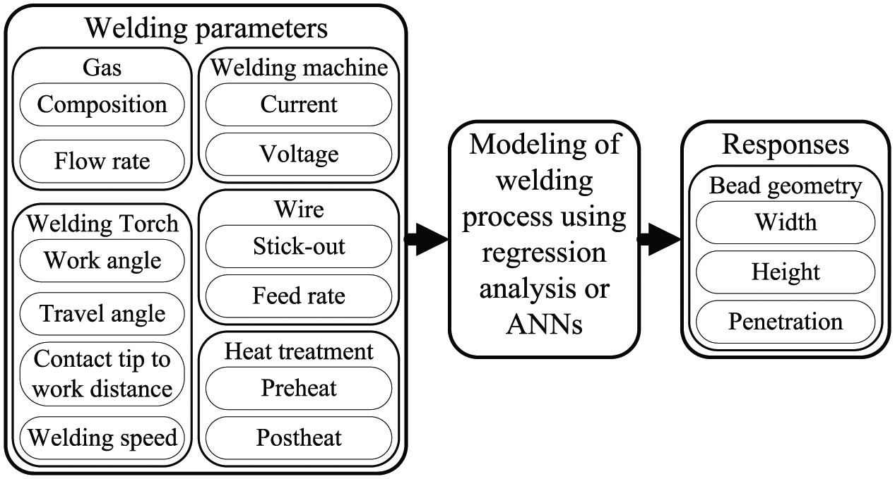
The inputs and outputs of the modeling of welding process
With the database, the relationship between the welding parameters and the geometry can be modeled using regression analysis or ANNs. For many combinations of the base and filler metals, it is common to have several parameters that do not change and remain constant. Hence, the parameters are categorized into constants and variables during the modeling process. The modeling results show implicit or explicit functions of the variable parameters, while constant parameters provide reference to the conditions. The relationship can also be built using a selective combination of variable parameters for different welding settings in which all the welding parameters may not be independent of each other, for instance, arc voltage and feed rate are set to be dependent on welding current in many welding equipments. In this research, however, three welding parameters, namely, welding speed, welding current and arc voltage, are used to establish the weld bead model, and they can be defined independently.
Pass planning for nonuniform groove geometry
Welding groove representation and groove segmentation
Figure 2(a) depicts a computer-aided design (CAD) model of a scaled-down Y-joint structure, which consists of a main pipe and a branch pipe with a 45° intersection angle between the two pipes. Figure 2(b) defines the corresponding welding groove model using a sequence of cross sections, with the bisector direction at each cross section separating the groove angle (or joint-included angle) into two equal bevel angles. For a uniform groove, as investigated in Yang et al. 2 and Yan et al., 28 welding pass planning can be reduced to pass layout planning for one cross section. In this research, pass planning to fill up a nonuniform groove is formulated to pass layout planning for a group of cross sections.
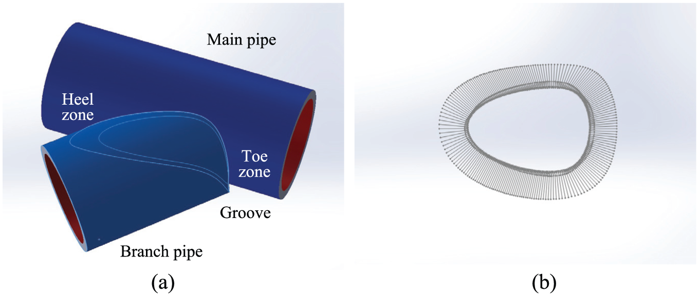
Scaled-down Y-joint structure: (a) CAD model and (b) welding groove with bisector direction.
The groove geometry of a Y-joint is nonuniform due to the presence of the varied groove angles and groove depths along the groove. Therefore, it is necessary to have multiple welding segments in order to have a more consistent welding pass solution. This is also in accordance with manual welding practices to reduce possible distortion in the welding zone. 29 Criteria for identifying welding segments are the reachability of a welding robot being used, welding position, groove angle or groove width variations. The groove angles are wider at the toe zone, while the groove depths are deeper at the heel zone. If an uphill welding direction is allowed only, at least two segments are needed. Typical numbers of segments are 2, 4 or 6, as illustrated in Figure 3. Having too many segments is not recommended as this would introduce extra welding breaks, leading to a higher possibility of porosity which can compromise the welding quality.
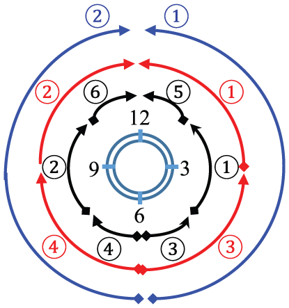
Groove segmentation scheme with uphill welding direction.
Welding bead model
Before pass planning, three assumptions have been made in this research. They are (1) the weld bead section can be approximated using a parabola function; (2) the overlapped area between adjacent passes or between the weld pass and the groove edge can be added into the valley area; and (3) the bead shape remains the same when welding parameters are not changed. According to Xiong et al., 12 a parabola function can be used to approximate the weld bead section accurately. Therefore, the bead shape is represented using equation (1) where h and w denote the bead height and width, respectively
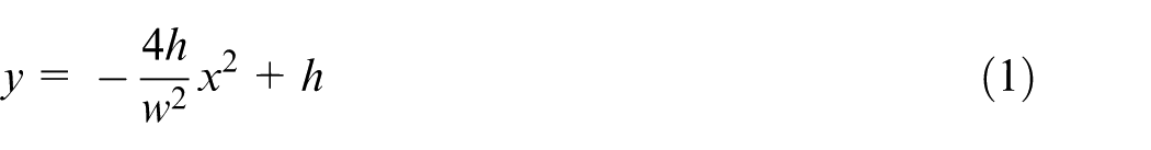
Figure 4 depicts the overlapped area and valley area in the second assumption. The experiments reported by Cao et al. 11 and Xiong et al. 12 show small deviation from the predicted results using the second assumption. In order to maintain a flat surface for each layer, the bead heights of all the passes in a layer should be the same and the overlapped area should be equal to the valley area. Figure 4 shows the section view of a single layer of a groove which is to be filled. If n denotes the number of passes in the layer; wi denotes the bead width of the ith pass; xi specifies the location of the ith pass in the x direction; S denotes the area; and P1, P2, P3 and P4 denote the intersection points of the layer surfaces and the groove edges, equation (2) can be obtained from equal overlapped area and valley area
The pass planning of a single layer in a groove cross section.
In equation (2), the unknown variables include wi and xi if the number n and bead height h have been defined. The number of unknown variables is 2n, but equation (2) has n + 1 linear equations. If n > 1, various solutions can be obtained. In order to guarantee a unique solution, the bead widths of all the passes in a layer are required to be equal. If the groove edges are straight lines and xPi denotes the x coordinate of the intersection point Pi, equation (3) can be obtained
Welding pass planning scheme for a groove segment
Each groove segment can be represented by a cluster of cross sections with an uphill sequence. For a uniform welding groove, the pass planning process can be reduced to pass layout planning to fill the weld bead in a cross section, and the number of layers and the number of welding passes can be maintained in the rest of the cross sections without changes in the welding parameters. However, this scheme will fail to plan the passes for a nonuniform groove as it will either end up with too many segments or require significant adjustment of the welding parameters in order to generate the varied size of the welding bead along the pass. As shown in Figure 5(a), the height of the welding beads from the start to the end of the given segment would need to be reduced significantly to achieve equal number of layers; this will, in turn, demand the associated welding parameters to be changed to weld this particular pass. Modern robotic welding systems can alter welding parameters during a single welding pass, but this is not recommended as this could affect welding penetration, etc. which may result in a low quality weldment.
Pass planning schemes in welding a segment: (a) maintain equal number of layers and passes and (b) maintain equal number of passes in each layer.
With these considerations, a layer-by-layer pass planning scheme is proposed, as illustrated in Figure 5(b), in which the number of pass layers for all the cross sections along a given segment does not have to be equal. During the planning of the current layer, the number of passes is maintained, and suitable bead heights and bead widths are searched to fill the groove without considering the requirement for the following layers. Weaving technique is allowed to accommodate variable groove widths during welding planning. After the current layer, the sections which have been filled up will be excluded in the planning of the next layer. Due to the uncertainty of the following layers, the final layer may exceed the top boundary of the groove. In this research, it is assumed to be allowed since in practice, cap passes will be needed as the final layer on top of the filling passes to complete the welding.
Optimization of pass planning
Pass planning for a groove segment involves two levels of optimization, namely, local optimization with respect to individual cross section and global optimization with respect to the groove segment. Figure 6 presents a flowchart for pass planning and optimization for a groove segment.
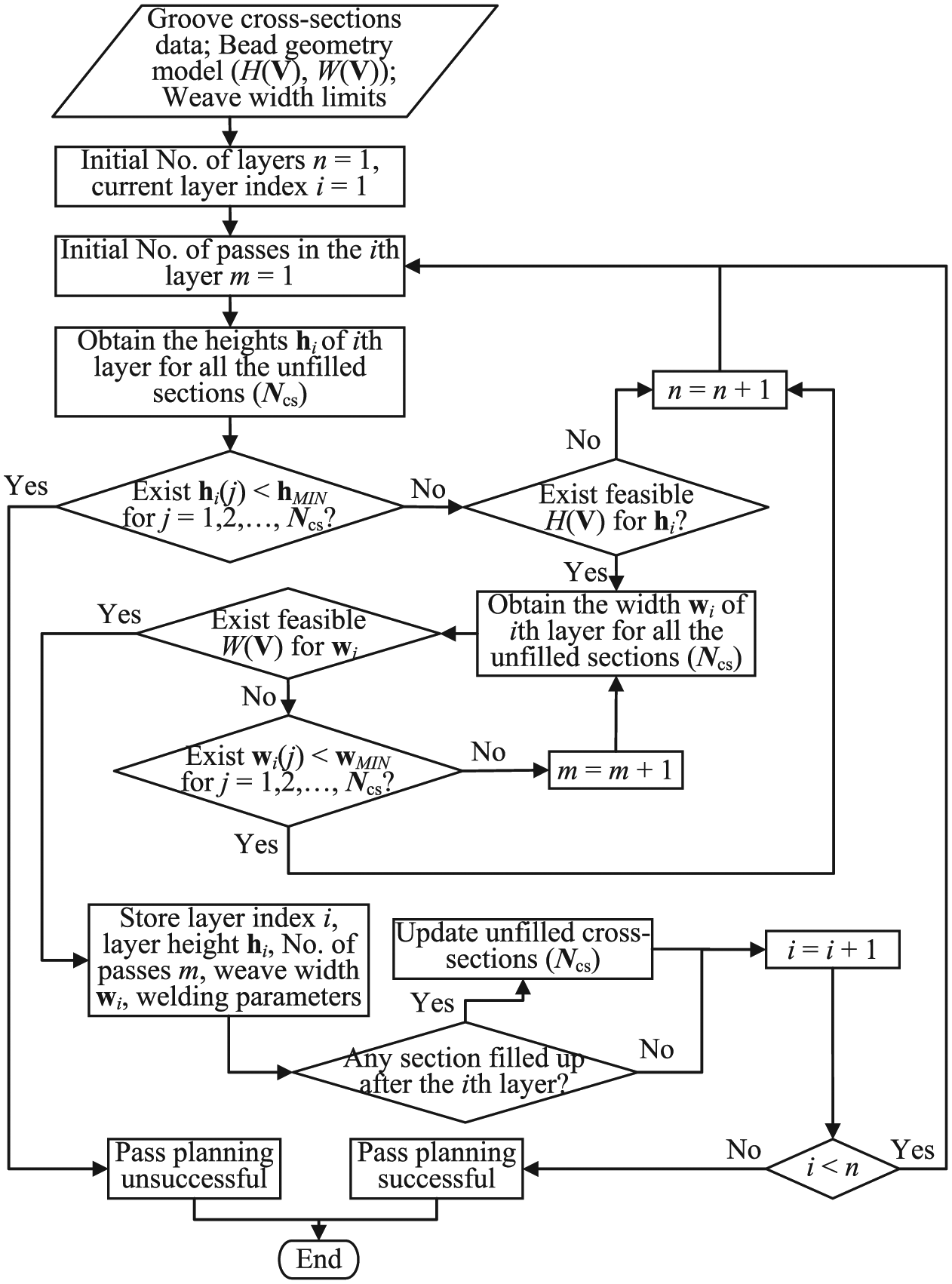
The flowchart of optimal pass planning for a groove segment.
Pass optimization in individual cross section
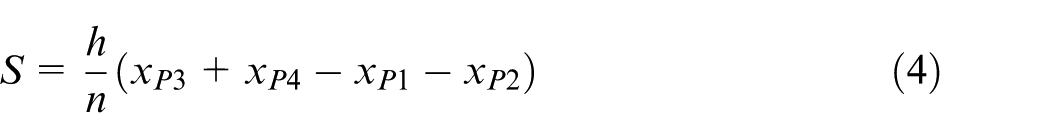
The objective of pass planning optimization for a single cross section is to fill the section using the minimal number of passes since fewer numbers can increase welding efficiency and decrease the possibility of producing defects among adjacent passes. In order to achieve this goal, the section area of the weld bead can be maximized, as a larger weld bead can decrease the number of passes in a defined groove. Hence, the objective function is to maximize equation (4), where xPi is dependent on the groove shape and the bead height. The variables include h and n
During maximization, n must be a positive integer and the values of h and w are subject to the constraint that the bead shape can be achieved using feasible welding parameters. With the knowledge database introduced in section “Knowledge database for welding,” the relationship between the bead height h, bead width w and welding parameter vector

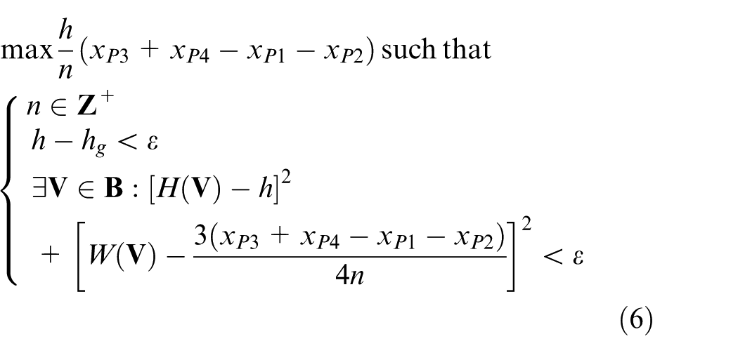
Since the bead width w can be obtained using equation (3), the optimization can be specified using equation (6), if ε denotes the tolerance defined by the users, and hg denotes the distance between the bottom surface of the current layer and the top surface of the groove (Figure 4)
Pass optimization for a groove segment
The goal of pass optimization for a groove segment is the determination of the minimum number of passes to fill up the segment subject to the conditions that each pass can be generated with a set of consistent welding parameters. The overall optimization problem consists of optimization of four objectives, namely, (1) minimization of the difference between the desired values and predicted values of bead height, (2) minimization of the difference between the desired values and predicted values of bead width, (3) minimization of the variations of welding speed and weave width in one pass and (4) maximization of the total areas of bead sections for each welding pass. The third objective tends to select similar bead height and width to reduce the variation in welding speed and weave width; however, considering the variations in groove depth at different groove cross sections, the bead height is expected to be larger at the deeper location while the bead width is expected to be smaller at the narrower location. Besides this constraint, other constraints are the upper and lower boundaries defined in the variables, including bead height and welding parameters. The number of passes in the current planning layer should be an integer. Equation (7) is the final objective function, where fh is referred to the square root of the square sum of the differences of bead height, fw is the square root of the square sum of the differences of bead width, fp is the sum of standard deviations of welding speed and weave width and fa is the reciprocal of the mean of the areas of bead sections

In equation (7), ωh, ωw, ωp and ωa are the weighted coefficients for the four objectives, respectively. The selection of these coefficients is based on the relative importance of these objectives. For instance, the difference between the desired value and the predicted value of bead height can be made up by the following layer; the difference is not as important as that of the bead width. The maximization of bead sections aims to decrease the number of layers. Therefore, these two objectives are comparatively less important. The minimization of the variations of speed and weave width aims to smoothen these two parameters, which is important for a consistent and smooth bead shape generated along the pass.
Case study and discussion
Pass planning of top-half groove
The CAD model of a Y-joint structure case study is shown in Figure 2(a). The two pipes have the same dimension, each with an inner diameter of 230 mm and an outer diameter of 327 mm, and the intersecting angle between the two pipes is 45°. As the axes of the two pipes are intersecting, the geometry of the top-half and the bottom-half of the groove model is symmetrical. Therefore, only the passes for the top-half of the groove are planned and optimized by addressing the variations in the groove angle and the groove depth. The top-half of the groove is modeled with 51 evenly distributed cross sections, which are further grouped into two segments, namely, toe segment and heel segment, as described in Figure 7.
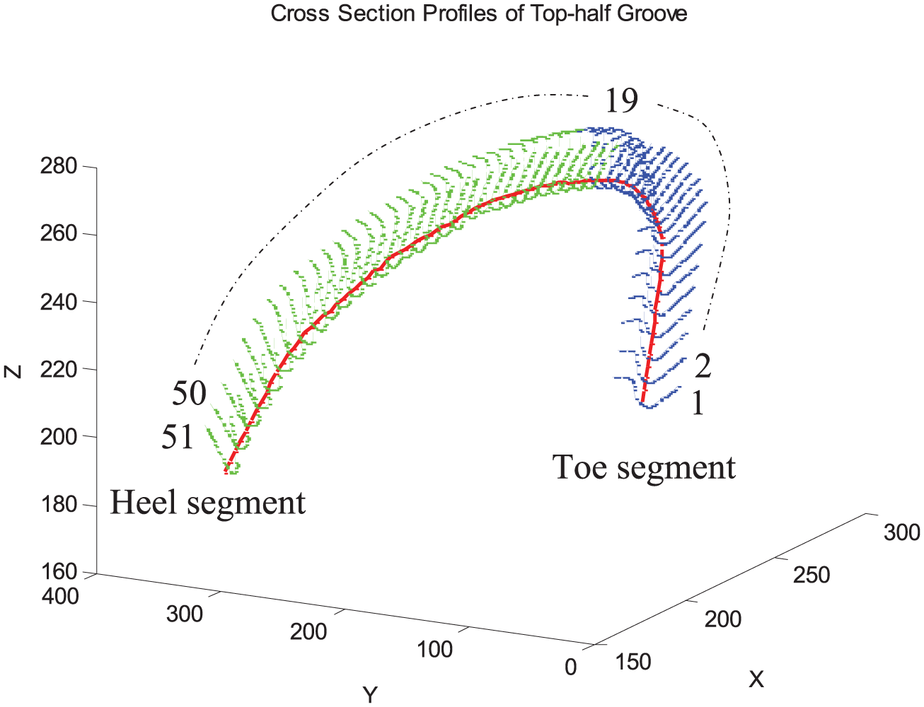
Groove representation with cross sections (top-half groove).
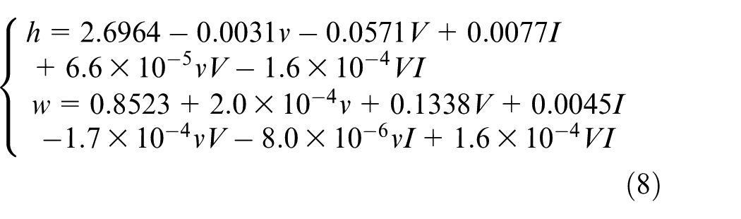
A group of experimental data in the database is used to develop the prediction model of the weld bead geometry. The experiment uses a mild steel plate as the base metal. The filler metal is steel wire with diameter of 1.2 mm. Pure argon is employed as the shielding gas. Table 1 lists the values of the welding current, voltage and speed and the corresponding bead heights and widths. With the experimental data, equation (8) is obtained using regression analysis where I denotes the current, V denotes the voltage and v denotes the welding speed
Welding parameters and corresponding bead dimensions
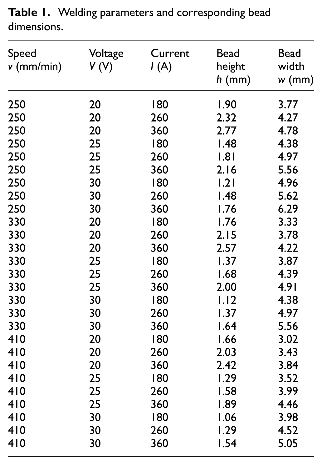
From Table 1, it can be seen that the ranges of speed, voltage and current are 250 ≤ v ≤ 410, 20 ≤ V ≤ 30 and 180 ≤ I ≤ 360. Figure 8 shows the comparison between the experimental results and the prediction values of the bead height and bead width using equation (8). It can be seen that there are small deviations between the prediction values from the experimental results. With the parameter ranges and equation (8), the maximum bead area can be obtained, which is 8.62 mm 2 when h = 2.704 mm and w = 4.872 mm.
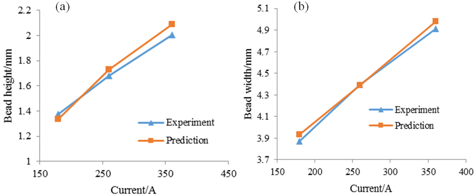
Experimental and prediction values for (a) bead height and (b) bead width, with 25 V voltage and 330 mm/min welding speed.
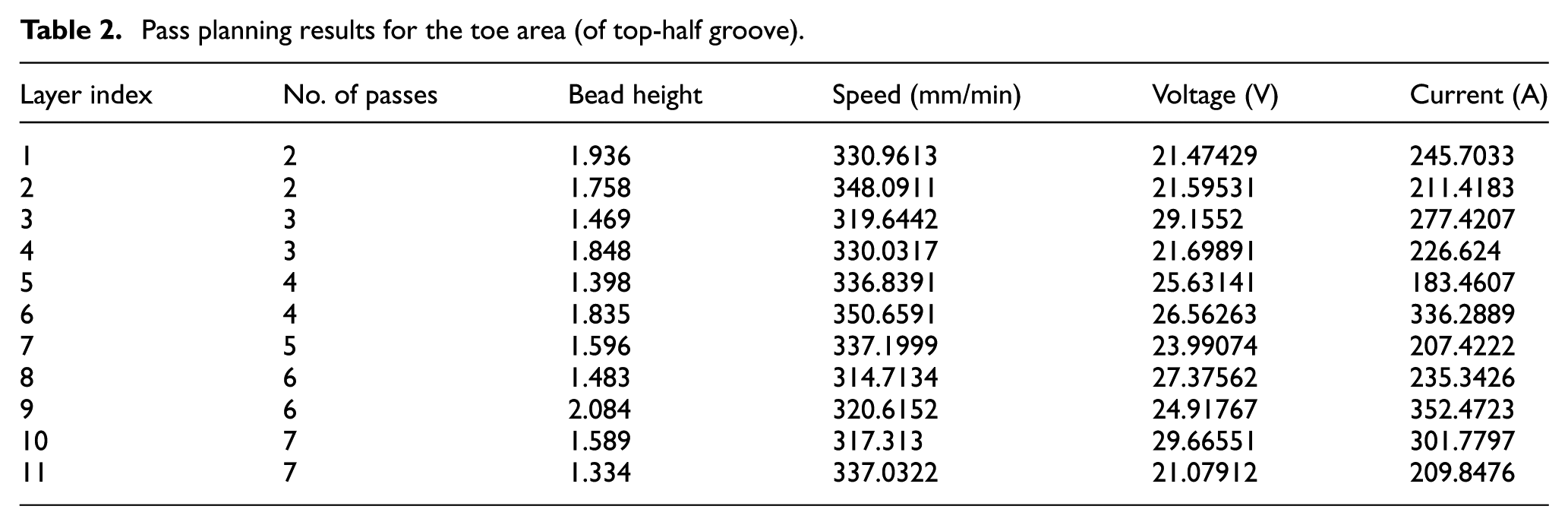
Due to the root opening, which makes it difficult for robotic welding, the root pass is assumed to be completed by manual welding, and it is excluded from the pass planning. Tables 2 and 3 summarize the pass planning results for the toe area and the heel area, respectively, including the number of layers, the number of passes and the associated welding parameters for each layer.
Pass planning results for the toe area (of top-half groove).
Pass planning results for the heel area (of top-half groove)
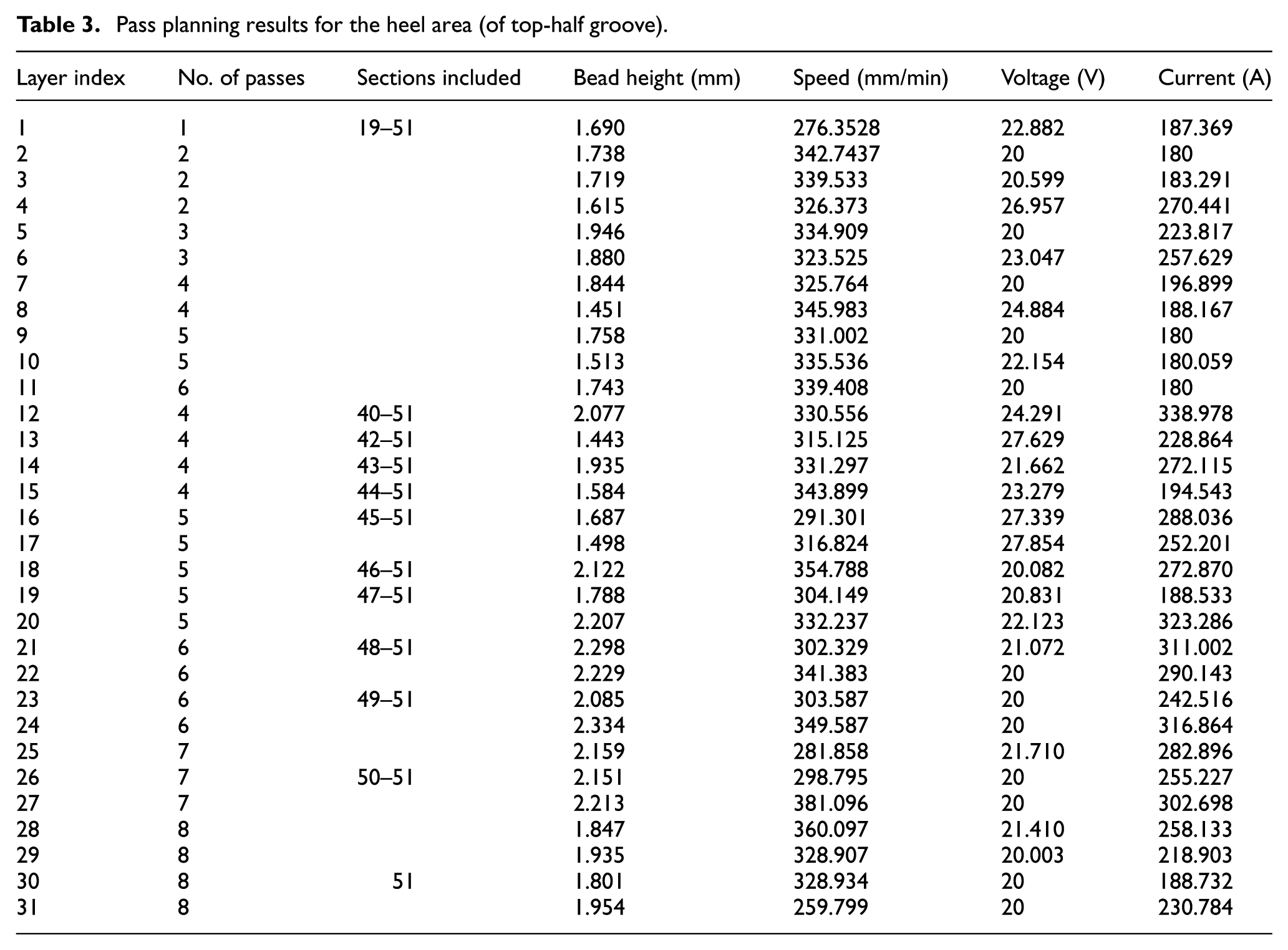
In planning the toe area, the four coefficients in equation (7) were set to ωh = 0.1, ωw = 0.5, ωp = 0.3 and ωa = 0.1. The entire toe segment can be filled up with equal number of layers and passes, that is, 11 layers and 49 passes in total. In planning the heel area, the four coefficients in equation (7) were set to ωh = 0.1, ωw = 0.7, ωp = 0.1 and ωa = 0.1. The heel segment requires 31 layers and 155 passes in total. In particular, after 11 layers, half of the heel segment can be filled up, and the remaining portion can be gradually filled up with more layers. Both toe and heel segments allow weaving to reduce the total number of passes needed. Layers 12–15 have fewer passes than the previous layer (layer 11) due to the increase in their weave width.
Discussion
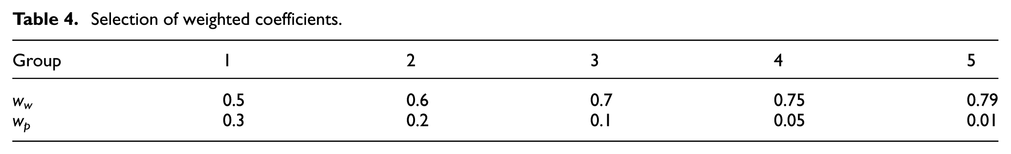
The effects of the selection of weighted coefficients in equation (7) on the smoothness of the resulting welding parameters and weld bead shape were investigated. As the objectives on minimizing the bead height (fh) and maximizing the bead sections (fa) are relatively less important, the two coefficients associated were set to 0.1. The other two coefficients ww and wp were investigated in detail. A total of five set of values of these two coefficients are given in Table 4, and the pass results in comparison with the section of weighted coefficients in the toe area and heel area are illustrated in Figures 9 and 10.
Selection of weighted coefficients.
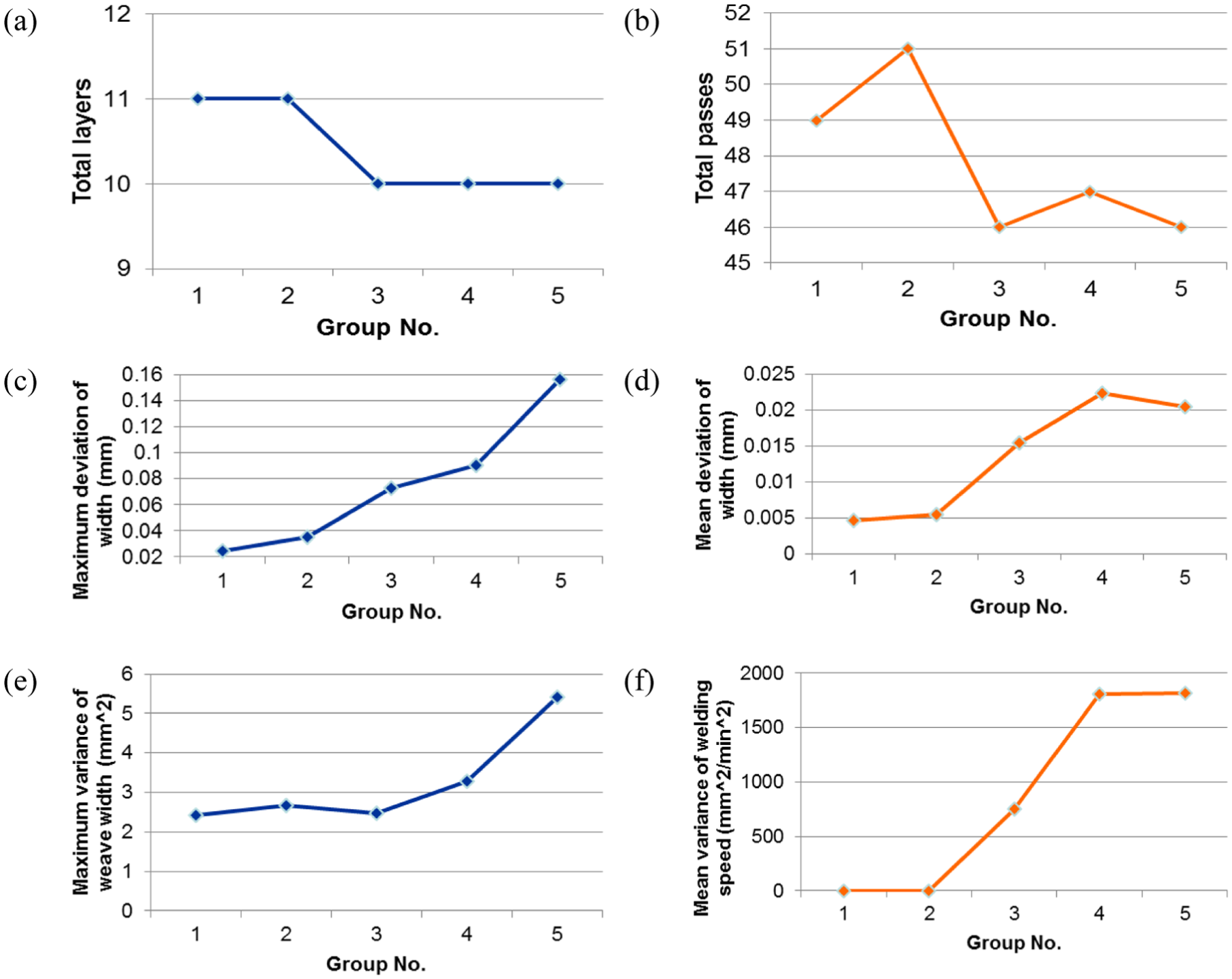
Pass results in comparison with the section of weighted coefficients in toe area: (a) total number of layers, (b) total number of passes, (c) maximum deviation of bead width, (d) mean deviation of bead width, (e) maximum variance of weave width and (f) mean variance of weave width.
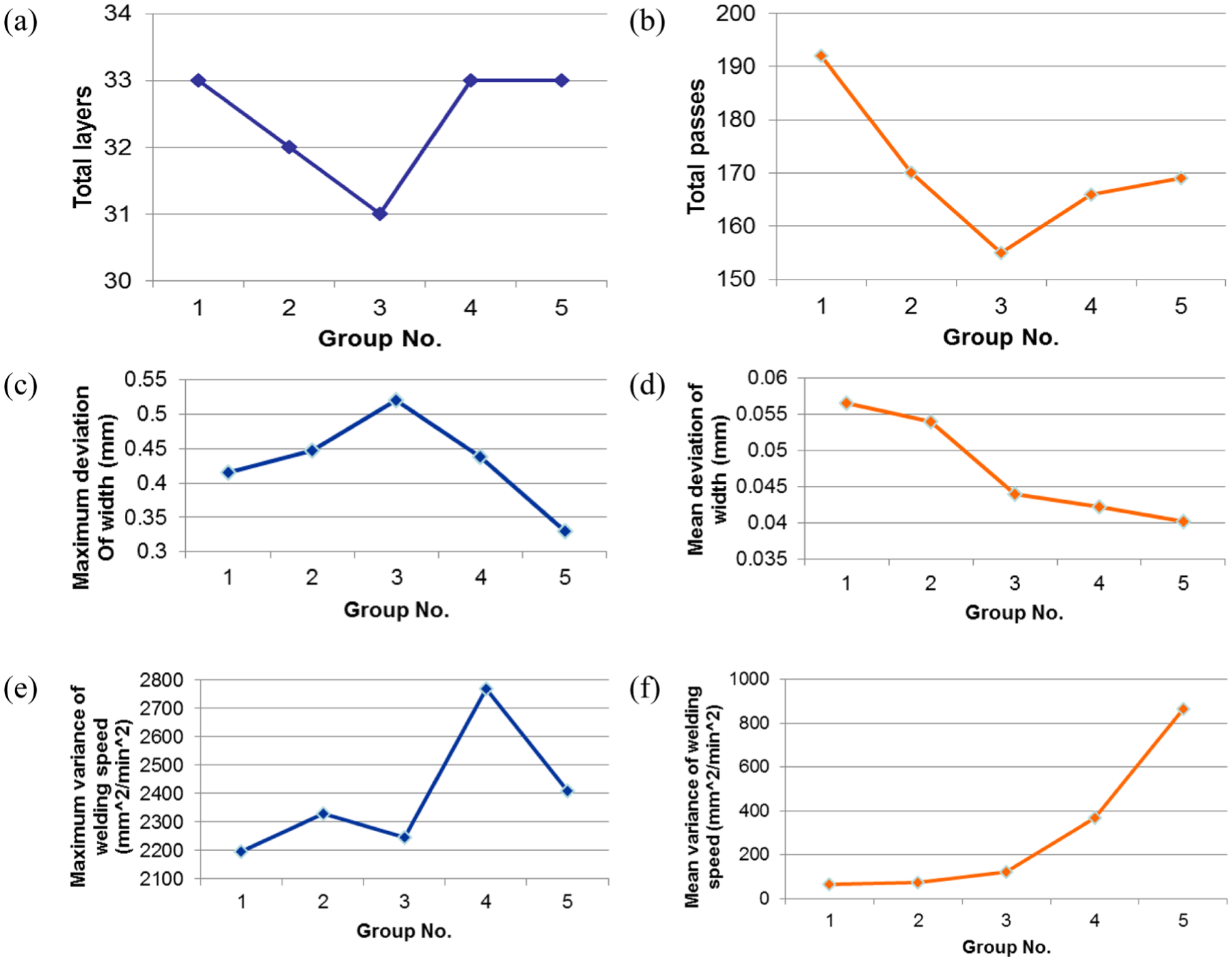
Pass result in comparison with the section of weighted coefficients in heel area: (a) total number of layers, (b) total number of passes, (c) maximum deviation of bead width, (d) mean deviation of bead width, (e) maximum variance of weave width and (f) mean variance of weave width.
It can be concluded based on Figures 9 and 10 that among the five groups of coefficients, group 1 gives the best option for the coefficients for the toe area with which the total numbers of layers and passes are slightly larger than the minimum values, while the deviation of bead width, the variance of weave width and welding speed have the least values. Group 3 gives the best selection of the coefficients for the heel area with which the total numbers of layers and passes are the smallest, and the mean deviation of bead width variance of weave width and welding speed is moderate compared to the other four options of weighted coefficients.
Conclusion
The welding parameter knowledge database is able to provide accurate welding bead geometry prediction models. The models can be used to predict bead shapes with the given welding parameters. The welding parameters can also be obtained to achieve defined bead shapes using the prediction models.
The optimization algorithm for pass planning maximizes the section areas of the weld bead in every layer to achieve minimal number of welding passes. Optimization constraints are applied to maintain consistent welding parameters for each welding layer as well as for each individual welding pass. The planning result provides the number of layers, number of passes in each layer and the corresponding welding parameters. The case study shows that the proposed method is able to provide feasible solutions for the pass planning of a nonuniform groove, and the weld beads of all the passes can be achieved using feasible welding parameters.
Footnotes
Appendix 1
Declaration of conflicting interests
The author(s) declared no potential conflicts of interest with respect to the research, authorship and/or publication of this article.
Funding
The author(s) disclosed receipt of the following financial support for the research, authorship, and/or publication of this article: This research was supported by the Agency for Science, Technology and Research (A*STAR), Singapore, and SERC Industrial Robotics Program on Robotic Welding of Complex Joint (project no. 1225100006).