
Abstract
Sapphire is an important material for optical applications, but the anisotropy of key properties makes it difficult to obtain uniform ground surface. In this work, cross-grinding experiments were first conducted on C- and M-planes of sapphire to investigate the dependence of the ground surface quality on crystal orientation. Then, scratching tests were performed along the specific crystal orientations to explain the formation mechanism of the anisotropic grinding patterns. The results showed that the surface roughness distribution on C-plane is of a threefold symmetry, while one axis of symmetry for M-plane. The damage pits on C-plane possess lower aspect ratio than that on M-plane. By combining the scratching-induced fracture features with the contact-induced deformation theory of sapphire, it was found that the propagation of the primary cracks in sapphire is accompanied by activating different deformation systems. The material removal on C-plane is dominated by the shallow lateral cracks, which propagate parallel to the ground surface and result in shallow and wide pits. However, the deep lateral cracks play an important role on M-plane, which intersect with the ground surface and cause deep and dense defects. The non-uniformity of the ground surface is attributed to the appearance of radial cracks for C-plane, while it is associated with the number of the available deformation systems for M-plane.
Introduction
Sapphire is an increasingly popular material that has been widely used for precision optics, forward looking infra-red (FLIR) windows, and substrates for blue light-emitting diodes (LEDs) for its excellent thermal and mechanical performance, as well as the superior optical clarity over a broad spectral range.1–3 All of the above applications require sapphire to possess high machining quality and defect-free surfaces. However, in addition to the extremely high hardness and brittleness, the inherent anisotropy of sapphire adds further difficulty to machining of uniform surface with high quality. Especially for cross-grinding of rotationally symmetrical surface where the workpiece rotates periodically and the material removal is completed along various crystal orientations. 4 Therefore, a further investigation on the crystal orientation dependence of the material removal mechanism would contribute to the control of surface/subsurface damage and shorten the time of polishing process.
Sapphire is a typical difficult-to-machine material, and ultra-precision grinding is the dominant technology used to achieve the required surface quality. 5 It has been reported that high surface integrity can be obtained if the grinding process is conducted in ductile regime.6,7 Early studies about sapphire grinding were mainly based on the performance of diamond wheels, including the grain size, concentration, bond material, etc.8–10 More recently, ultrasonic vibration assisted grinding (UVAG) of sapphire was conducted to improve the grinding wheel state and promote the ductile material removal.11–13 Besides, Wu et al. 14 investigated the chemical mechanical grinding (CMG) of sapphire by a new chromium oxide (Cr2O3) grinding wheel, and a high material removal rate and better surface quality were obtained. These focused studies on sapphire machining provided valuable information on restriction of brittle fracture and improvement of machining efficiency, but the dependence of grinding surface quality on the crystal orientation was not discussed.
Different from polycrystalline materials, anisotropy is an additional factor that affects the machining surface quality for single crystals.15–17 Numerous studies on machining of single-crystal optical materials, such as potassium dihydrogen phosphate (KDP) crystal, single-crystal calcium fluoride, single-crystal silicon, and 3C-SiC, have elucidated that the machined surface roughness, machining forces, micro-fracture topography, and brittle–ductile transition (BDT) are all affected by the crystal orientation.18–22 For example, the cutting force and the BDT depth remarkably change depending on the crystal orientation of KDP crystal, resulting in the obvious variation of surface roughness.23,24 The anisotropic machining patterns are highly related to the slip systems and cleavage planes of the workpiece material. For instance, the better surface quality of single-crystal calcium fluoride appears when the cutting direction is parallel to the slip system and perpendicular to the line of intersection between the cleavage plane and the machining surface.25,26
For sapphire, the crystal anisotropy results in that the indentation cracks propagate mainly along the well-defined crystal orientations. 27 As an illustration, the c-axis compression causes twinning on R-planes, and intersection of twins on different R-planes contributes to fracture. 28 The R-plane is the weakest plane of sapphire, and fracture is more likely to occur where the tensile stress is high and in direction of the weak plane. 29 Besides, the C- and A-planes of sapphire exhibit the greatest anisotropy in scratching hardness, and the C-plane demonstrates the highest resistance to surface fracture. 30 However, the ground surface roughness of A-plane is lower than that of C-plane because the machining-induced cracks on C-plane are at a larger angle to the machined surface compared with that on A-plane. 31 This study preliminarily stated the influence of crack orientation on the machined surface roughness for different crystal planes of sapphire. Furthermore, Wasmer et al. 32 conducted parametric experiments on A-plane of sapphire and found that grinding along the c-axis suffers a reduced grinding force compared with that along the m-axis. Mohammadi and Patten 33 investigated the effect of crystal orientation and laser power on the BDT depth of sapphire by laser-assisted scratching tests, and it is confirmed that different crystal orientations on C-plane have different BDT depths no matter with or without laser assist. Although the anisotropy of machining force, BDT depth, and machining surface quality of sapphire has been reported in the earlier studies, the dependence of the material removal mechanism on crystal orientation is far from being fully understood. Particularly, the crystal structure-induced non-uniformity of the ground surface in specific crystal planes is rarely discussed for sapphire.
In this work, the crystal orientation dependence of the cross-grinding surface patterns was first stated, including the ground surface roughness, the distribution, and profile of the damage pits. Then, the contact-induced deformation theory was discussed, and the anisotropic damage mechanism arisen in cross-grinding was further investigated based on scratching tests.
Materials and methods
Materials
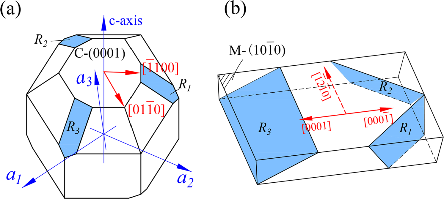
The commercially available synthetic sapphire (α-Al2O3) (Aurora Optoelectronics Co., Ltd, China) was used as specimen to investigate the anisotropic characteristics of material removal during cross-grinding and scratching processes. Figure 1(a) illustrates the coordinate system and crystal structure of sapphire. All crystal planes are defined relative to the C-plane which is of physical and optical symmetry. A- and M-planes are all perpendicular to C-plane, while R-planes are located at 57.6° relative to it. For simplicity, the R-planes including
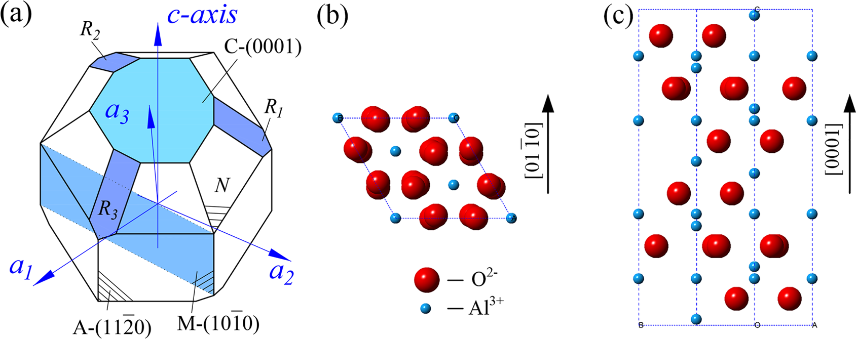
The spatial locations and atomic arrangements of the investigated crystal planes of sapphire: (a) the coordinate system and spatial locations of C- and M-planes and (b, c) the atomic arrangements on C- and M-planes.
Methods
First, the cross-grinding experiments were conducted on an ultra-precision grinding machine to investigate the crystal orientation dependence of the ground surface patterns on C- and M-planes of sapphire. The experimental setup is shown in Figure 2(a). An arc-shape resin-bonded diamond grinding wheel (Saint-Gobain Abrasives) was used for fine grinding after appropriate truing with a green silicon carbide stick. 34 Both the specimen and the grinding wheel rotated clockwise. The detailed machining parameters are listed in Table 1. The ground surface morphology was characterized by both optical microscope and scanning electron microscope (SEM, Zeiss, supra 55 sapphire). The micro-topography of ground surface damage was detected with an atomic force microscope (AFM, Bruker, Dimension Icon). The ground surface roughness was measured by a contact probe profilometer (Talysurf PGI 1240) from center to edge.
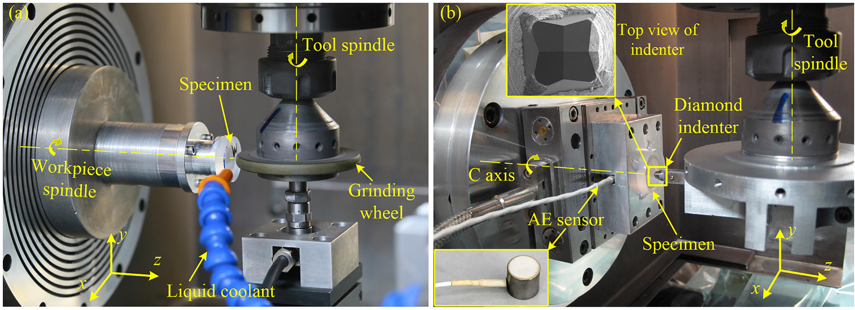
The experimental setups of (a) cross-grinding and (b) scratching.
Cross-grinding and scratching parameters.
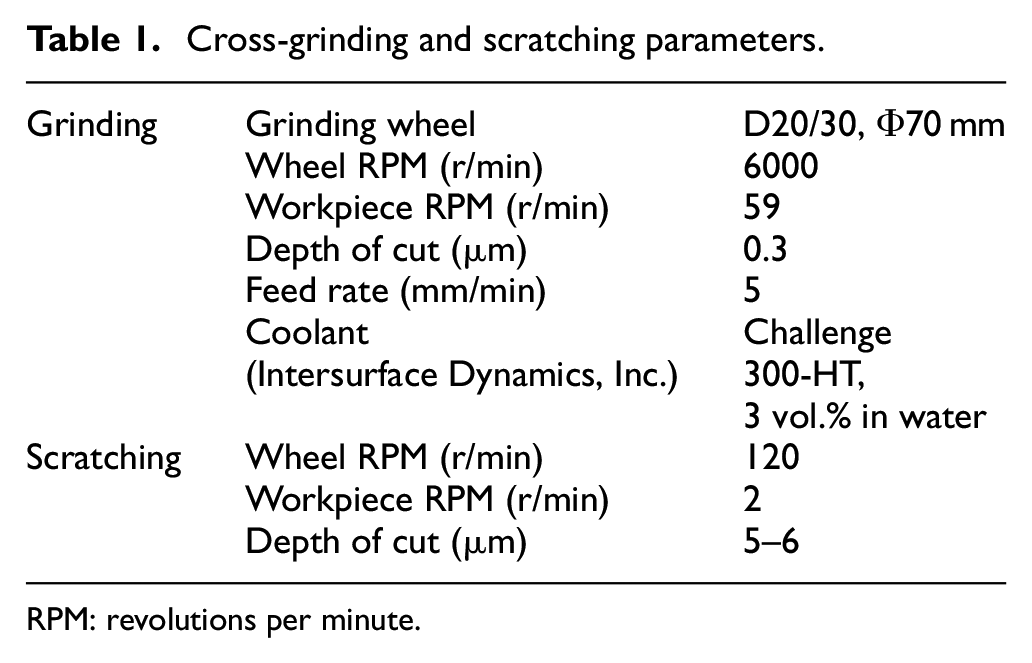
RPM: revolutions per minute.
Then, the formation mechanism of the non-uniform ground surface was further discussed based on scratching tests on C- and M-planes of sapphire along the specific crystal orientations. The morphology of the scratching grooves reflects the material deformation within the crystal, and it is helpful to reveal the surface formation mechanism under cross-grinding. The scratching experimental setup is shown in Figure 2(b). The specimens were pre-polished progressively with diamond slurry (9, 3, and 1 μm) to remove the original surface defects. The scratching tests were performed by fly cutting with a Vickers pyramidal indenter (square-based diamond pyramid of face angle 136°, shown in the top left insert), which is rigidly fastened to an arbor and connected to the tool spindle. An acoustic emission (AE) sensor (Physical Acoustics Corporation, type WD, shown in the bottom left insert) was mounted under the specimen by an adapter plate to detect the indenter–specimen contact for tool setting. During this process, a LabVIEW-developed graphical user interface (GUI) was used to monitor the tool–specimen contact by dynamic AE signal, and the indenter fed toward the scratching surface in steps of 1 µm until the periodic AE spikes occurred to finish the tool setting. The scratching direction was kept parallel to one of the indenter diagonals. By controlling the processing parameters, as listed in Table 1, a series of non-overlapping scratching grooves along different crystal orientations were performed without coolant addition. The surface morphology of the scratching grooves was characterized by both optical microscope and SEM.
Anisotropy of cross-grinding surface quality
The cross-grinding surface patterns of C- and M-planes of sapphire are shown in Figure 3(a) and (b), together with the polar plots of the measured surface roughness (Ra) in Figure 3(c) and (d). It is obvious that the surface features are remarkably dependent on the crystal orientation. On C-plane, there are six damaged regions distributed in a radial pattern from the specimen center and show a simple threefold symmetry. The three arms of slightly pitted regions are observed along the
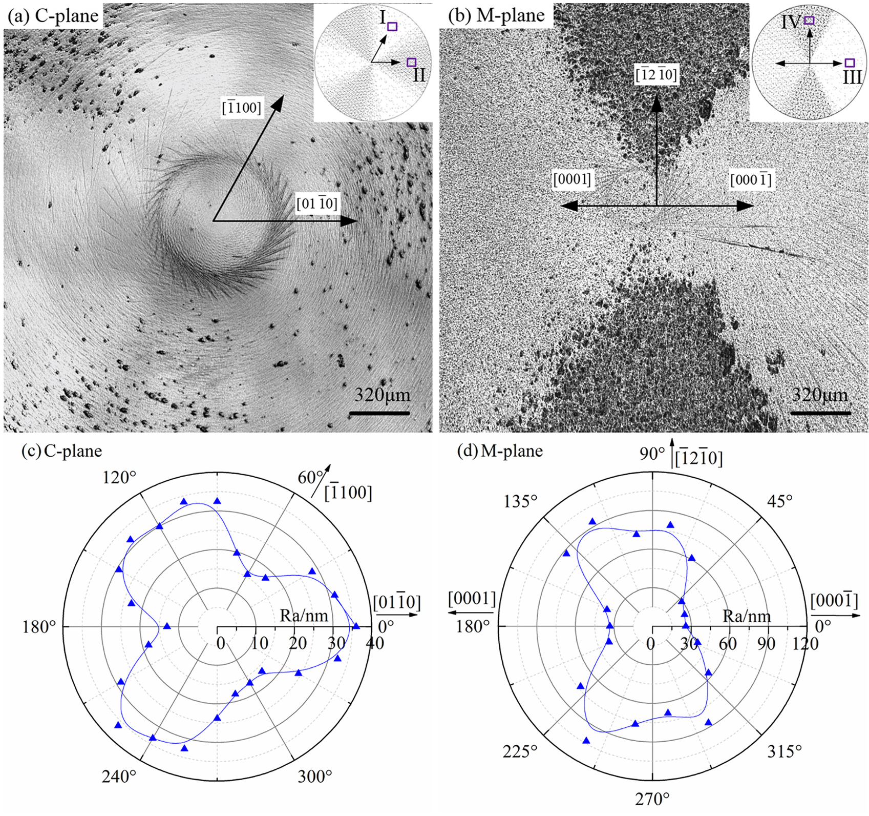
The crystal orientation dependence of the ground surface quality on C- and M-planes: (a, b) the central zone of the cross-grinding surfaces; insert, schematic representations of pitting damage distribution and (c, d) the surface roughness along various crystal orientations.
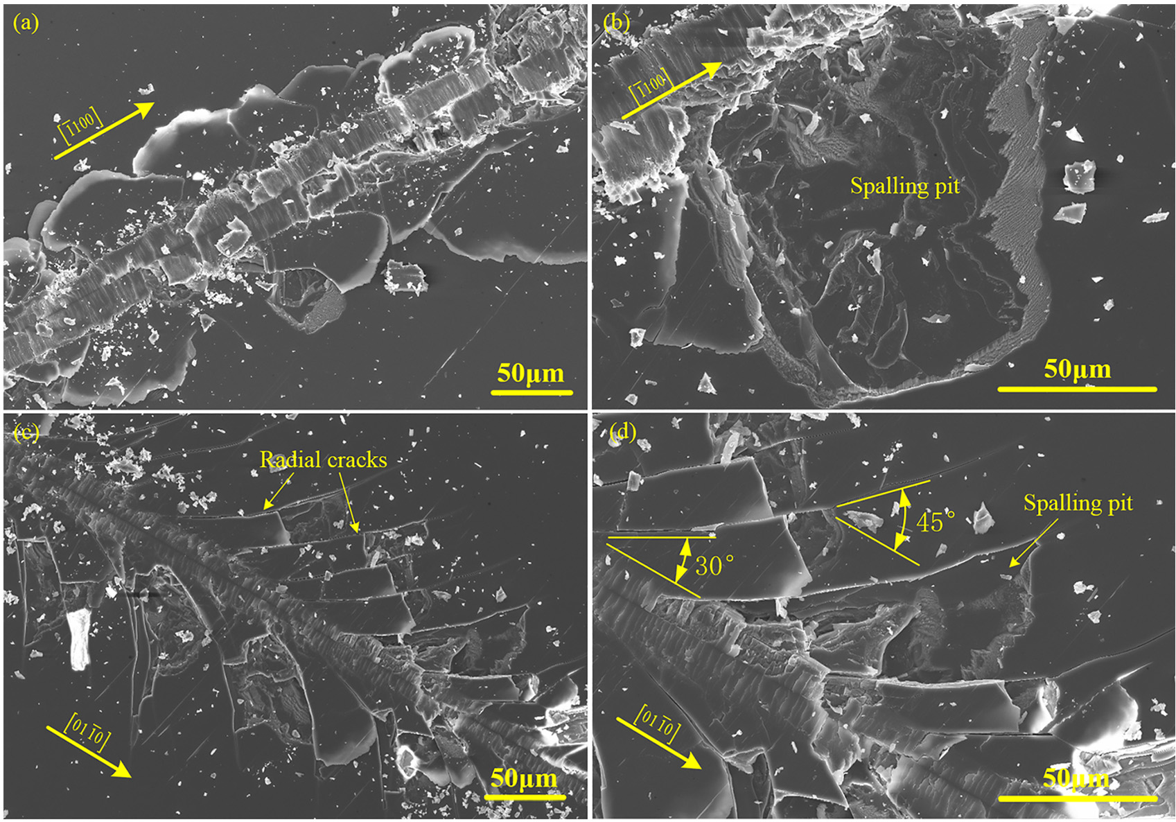
Figure 4(a)–(d) illustrates the distribution and the morphology of the grinding-induced surface damage, corresponding to the positions I–IV marked by wireframes in the insets of Figure 3(a) and (b), respectively. Figure 4(a) and (b) shows the typical cross-grinding surface morphology of C-plane along the
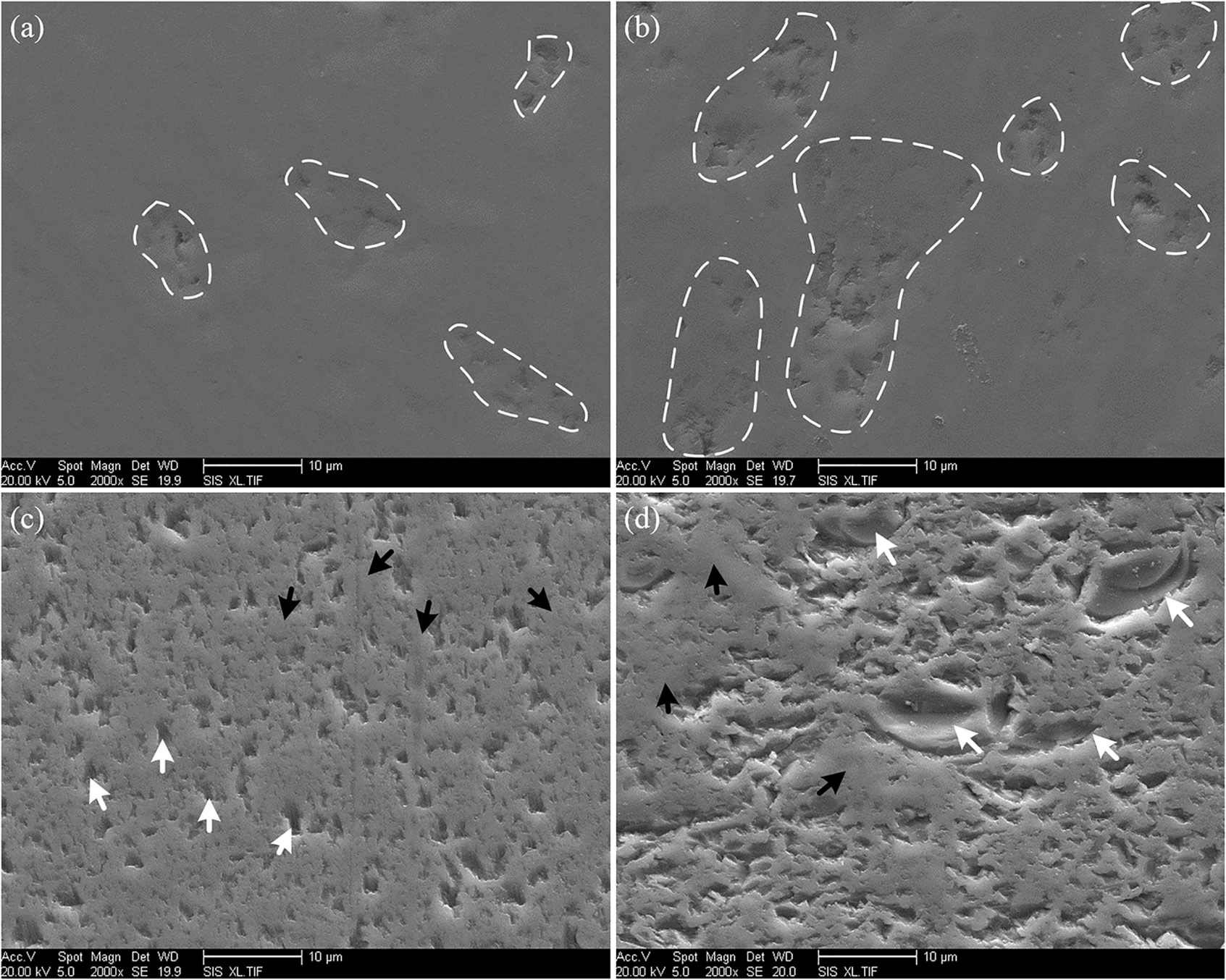
The cross-grinding surface morphology of C- and M-planes: (a, b) C-plane along the
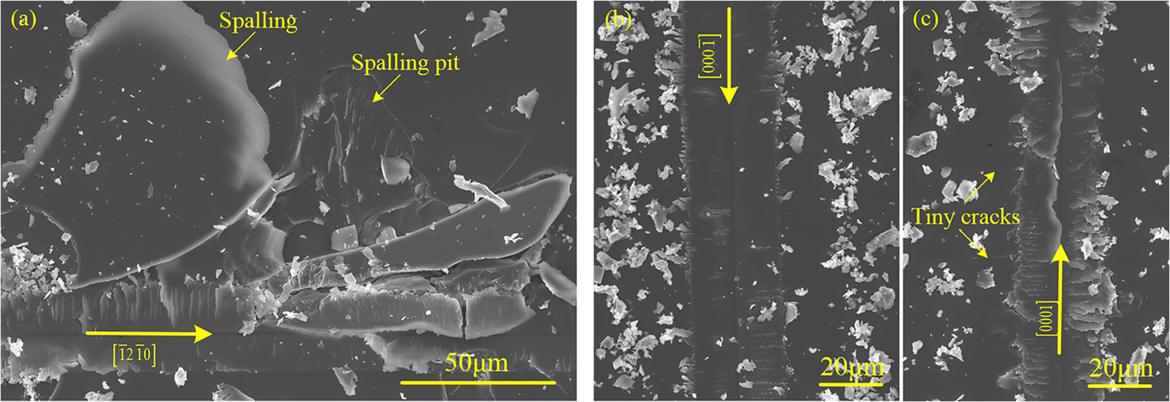
Figure 5 shows the micro-topography of the ground surface and the profile of the damage pits in-depth direction on C- and M-planes along various crystal orientations. The lines on the AFM images indicate the positions of the profiles shown below, and the horizontal and vertical arrow lines mark the width and depth of individual pits. The damage pits along the
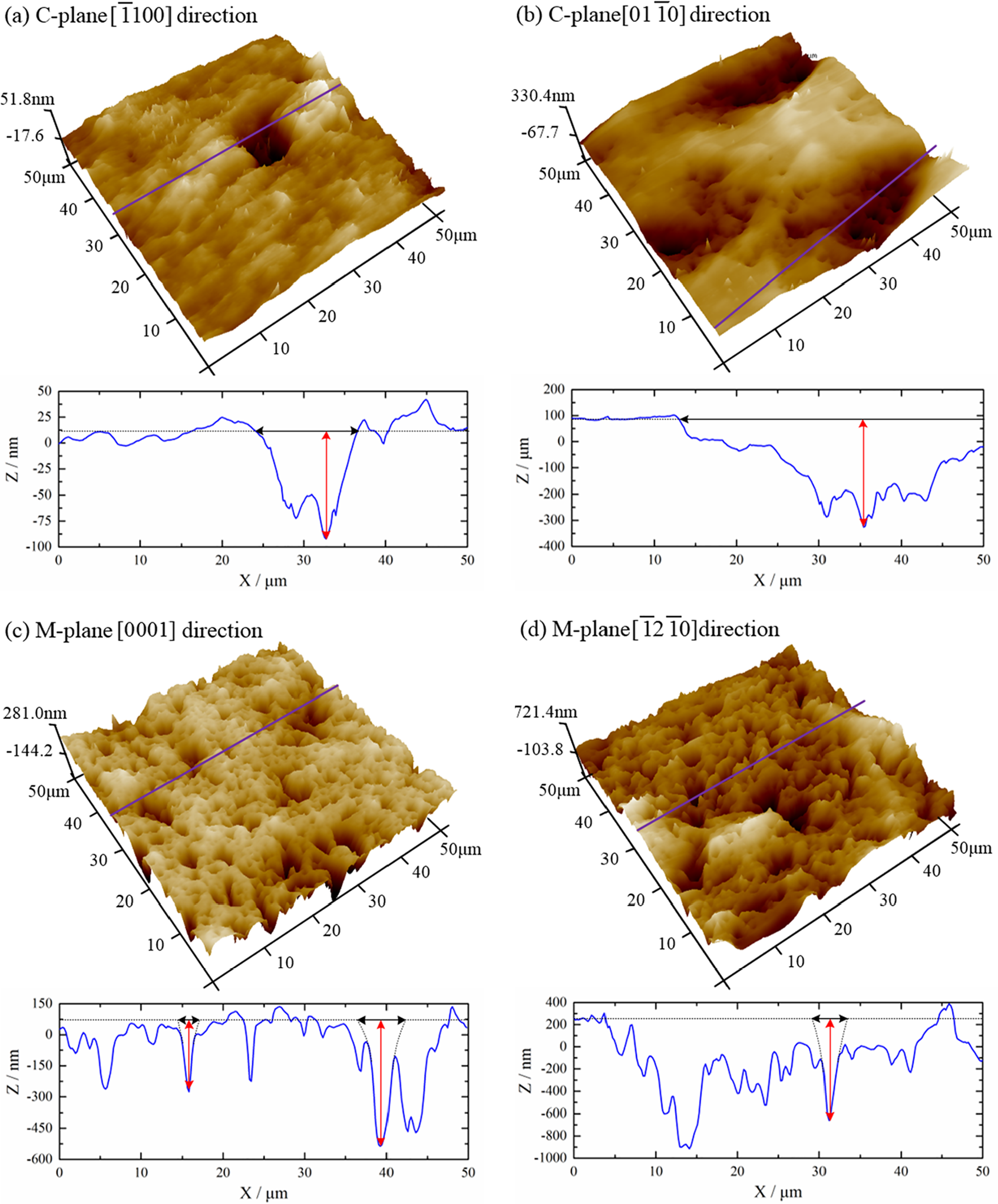
The micro-topography and profile of damage pits: (a, b) C-plane along the
Discussion based on scratching tests
The material removal in grinding process can be viewed as an integration of a set of single-grit cutting. The randomly distributed diamond grits participate in the material removal and determine the ground surface quality by affecting the formation of median/radial and lateral cracks. Therefore, an investigation into the material removal caused by single-point scratching can provide primary information on the surface generation mechanisms under grinding. Both ductile and brittle deformation developed during the grinding process are influenced by the cooperation of the crystal orientation and the stress field induced by abrasive grits. It is regarded that the special ground surface morphology is mainly caused by activating different slip/twinning systems.35,36 The activation of the slip/twinning systems depends on the resolved shear stress (RSS) τ, which is expressed as follows
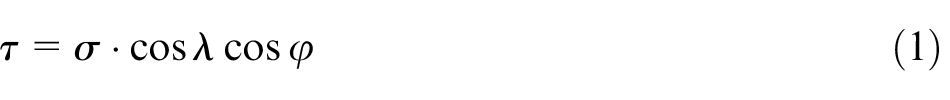
where σ is the average compressive stress on the indenter–specimen contact surface, λ and φ are the angles between the stress axis and the slip plane normal and the slip direction, respectively. Equation (1) indicates that the activation of the slip/twinning systems is greatly dependent on the crystal orientation of the evaluated surface. Nowak and Sakai 37 summarized the available slip/twinning systems of sapphire and proposed a model based on the effective RSS to estimate the probability to activate them. The probability Ti to activate the ith slip/twinning system is given by

where τCRi/minτCRi is the relative critical shear stress (RCSS) that refers to the ratio of critical shear stress of the ith slip/twinning system and the minimum of all possible critical shear stresses. The constraint factor Λ i denotes the orientation of the indented crystal plane.
According to equation (2) and the summarized RCSS,
37
the probability T of activating the basal and rhombohedral twinning systems was calculated based on the model of scratching on C- and M-planes with a Vickers pyramidal indenter, the results are illustrated in Figure 6. From the perspective of symmetry, the calculated probability T agrees well with the obtained surface roughness shown in Figure 3(c) and (d). Specifically, the dominated deformation systems involve threefold symmetry on C-plane, as shown in Figure 6(a). Basal twinning is dominant as scratching along the
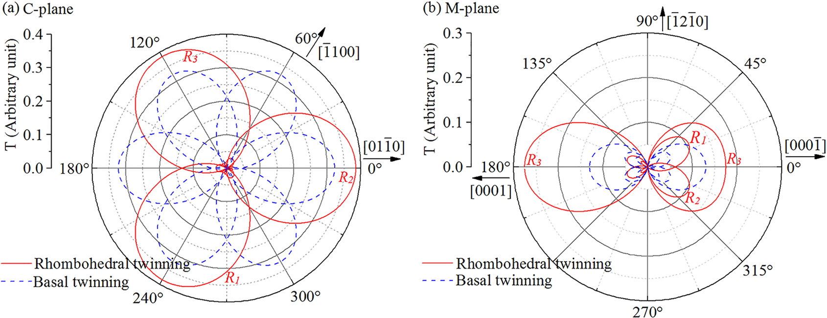
Probability (T) of activating the basal and rhombohedral twinning when scratching with the Vickers indenter on (a) C-plane and (b) M-plane of sapphire.
According to Figure 7, the crystal structure of C-plane shows threefold symmetry, and the M-plane is of one-axis symmetry. This phenomenon agrees well with the cross-grinding surface patterns shown in Figure 3 and verifies that the anisotropic ground surface quality is resulted from the crystal structure essentially. According to the symmetry of both the ground surface roughness and the crystal structure, the spatial locations of the investigated scratching directions are selected and indicated by the red arrows in Figure 7(a) and (b) for C- and M-planes, respectively.
The scratching directions (red arrows) on (a) C-plane and (b) M-plane.
Figure 8 shows the morphology of the scratching grooves on C-plane. Lateral cracks are dominant for scratching along the
Scratching patterns along different crystal orientations on C-plane: (a, b) along the
Scratching along different crystal orientations resulted in different fracture patterns, which is closely related to the anisotropy of cross-grinding surface quality. The brittle fracture in grinding process induces a continuously fissured layer under the abrasive grits, and the resulting cracks intersect with each other and lead to material spalling. Therefore, as the abrasive grits cutting along the
The morphology of the scratching grooves along the
Scratching patterns along different crystal orientations on M-plane: (a) the
Although the scratching grooves on M-plane show less brittle broken compared with that on C-plane, the subsurface cracks seriously propagated beneath the M-plane, which can be identified under the optical microscope by the diffused light from the crack interface. The subsurface cracks on M-plane can be defined as deep lateral cracks as they propagate outward but never reach the scratching surface and no catastrophic chipping occurs around the scratching groove, as shown in Figure 10(a). The previous study has confirmed that the lateral cracks propagate along the R-planes when scratching on M-plane. 38 Besides, the lateral cracks on C-plane can be defined as shallow lateral cracks which show quite different characteristics, as shown in Figure 10(b). First, the lateral cracks on C-plane intersect with the radial cracks and result in material spalling. Second, the diffused light indicates that the lateral cracks on C-plane are shallow and propagate at a smaller scale.
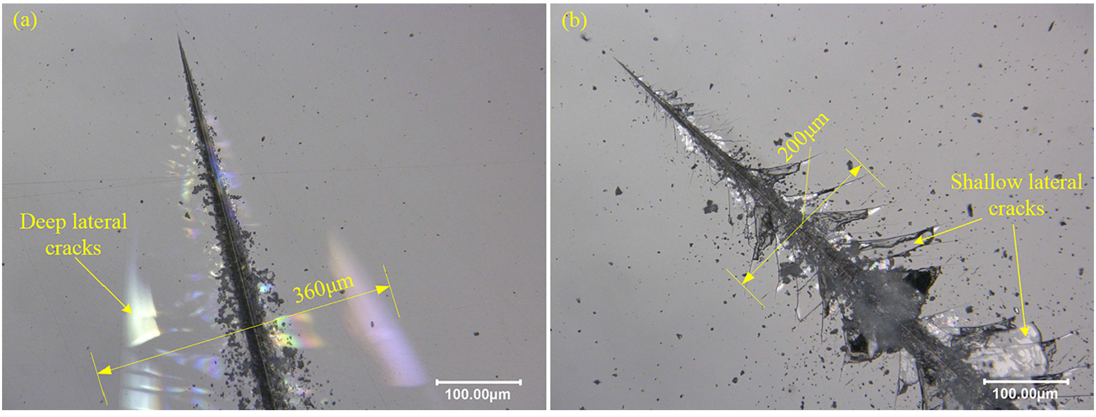
Optical microscope images of scratching grooves on (a) M-plane and (b) C-plane.
Based on the scratching results, it is found that the shallow lateral cracks on C-plane are parallel to the ground surface. In addition to preventing the propagation of the radial cracks, they also contribute to the material removal without destroying the new generated surface, as illustrated in Figure 11(a). Therefore, the damage pits on C-plane should be shallow and wide (low aspect ratio). This corresponds well with the experimental results illustrated in Figure 5(a) and (b). The deep lateral cracks on M-plane propagate along the R-planes and the slant angle relative to the ground surface make them destructive to the new generated surface, as shown in Figure 11(b). Besides, the shallow lateral cracks on C-plane propagate at a smaller scale compared with that on M-plane. This is because the fracture surface energy of C- and R-planes are 40 and 6 J/m2, 29 respectively. The high surface energy of C-plane makes it difficult to be broken, while the R-plane would be the preferred plane of fracture. The above analyses indicate that the damage pits on M-plane should be deeper and denser (higher aspect ratio) than that on C-plane, which is consistent with the experiment results illustrated in Figures 4 and 5.
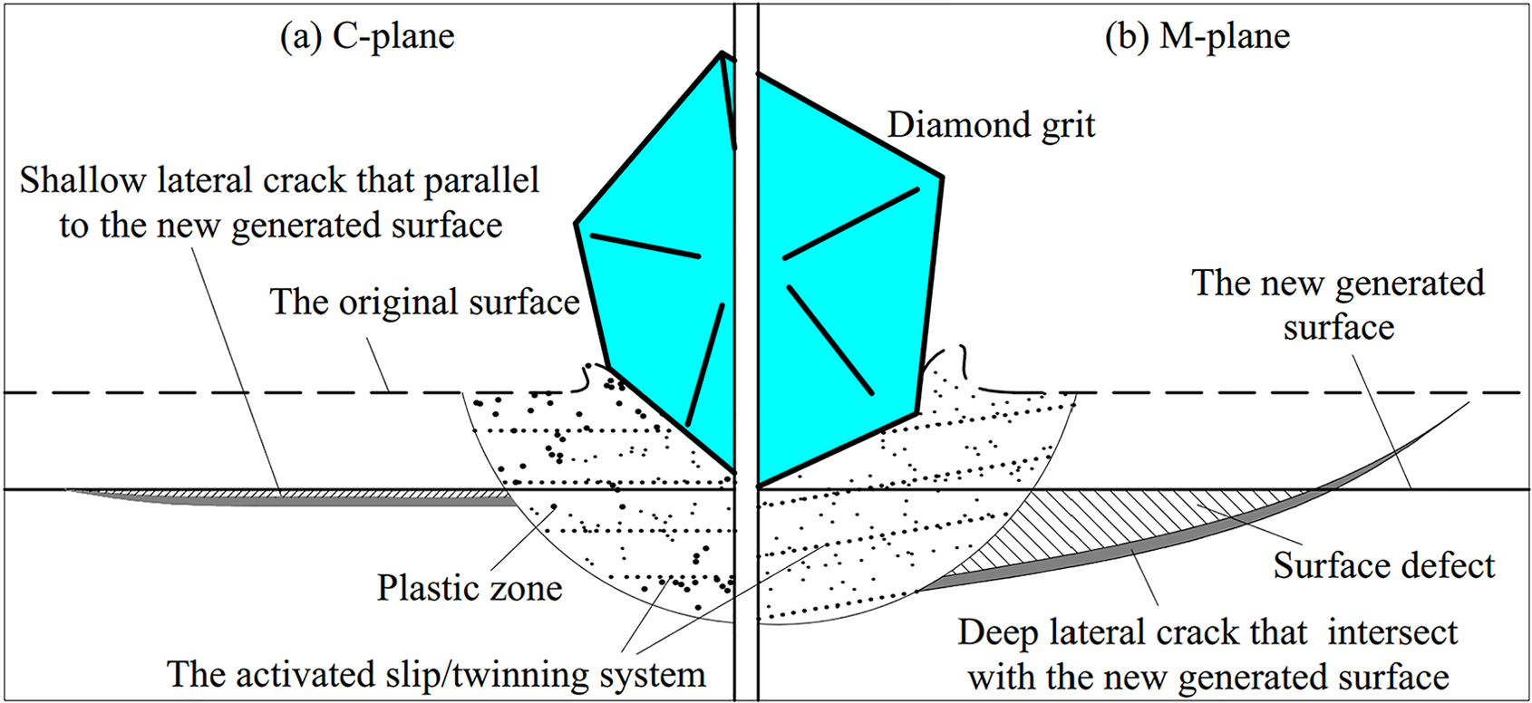
Model comparison of different material removal mechanisms between (a) C-plane and (b) M-plane.
Conclusion
The cross-grinding and scratching experiments were carried out on C- and M-planes of sapphire to investigate the crystal orientation dependence of material removal. The detailed results are concluded as follows:
The cross-grinding surface damage distributes in a radial pattern from the specimen center and shows a simple threefold symmetry on C-plane, while one axis of symmetry for M-plane. The damage pits on C-plane concentrate in local regions and possess a lower aspect ratio, while distribute uniformly and feature a higher aspect ratio on M-plane.
As grinding along the
On M-plane, the ground surface quality is dominated by the available deformation systems. Grinding along the
The profile of the damage pits is high related to the orientation of lateral cracks. The shallow lateral cracks on C-plane propagate parallel to the new generated surface and result in shallow and wide damage pits. However, the deep lateral cracks on M-plane intersect with the ground surface and cause deep and dense defects.
For ultra-precision machining of single crystals, the influence of crystal structure should be taken into account. Based on this work, the better surface quality could be obtained when grinding on C-plane along the
Footnotes
Declaration of conflicting interests
The author(s) declared no potential conflicts of interest with respect to the research, authorship, and/or publication of this article.
Funding
The author(s) disclosed receipt of the following financial support for the research, authorship, and/or publication of this article: This work was supported by National Natural Science Foundation of China (No. 51405108 and No. 51475119) and Aeronautical Science Foundation of China (No. 20140177003).