
Abstract
Spot welding has been a remarkably important joint method for automotive body engineering. Based on a simplified two-dimensional analytical model in a lap-shear specimen, the elastic analytical solutions near spot weld nugget are theoretically derived to analyze stress distributions. A Cartesian coordinate system is centered at the center of the nugget, and the shear or resultant force acting on the nugget is marked as the positive x-direction. The results show that the normalized radial and hoop stresses are negative at the angle intervals between [66.25°, 113.75°] and [246.25°, 293.74°], while the normalized shear stress is negative at the angle intervals between [0°, 90°] and [180°, 270°]. It can be observed that the locations with the initial yielding failure change gradually from the normalized radial distance of 1.34 to the circumference of the spot weld nugget, and finally to the infinity as the angle increases. The normalized effective stress could approach to 1.84 as the normalized radial distance goes to infinity. In addition, the obtained analytical solutions are validated in the comparison with numerical results. The locations with peak Von Mises stresses along the circumference of the spot weld nugget have a good agreement with the analytical solutions. It indicates that the initial yielding locations would likely occur at the four special angles of the spot weld nugget. Therefore, the derived stress distributions in this study are beneficial for analyzing yielding failure behavior or evaluating damage evolution on engineering structures jointed with spot welds.
Keywords
Introduction
In recent years, spot welds have been widely and extensively used to join sheet metals in the automotive industry and other transport vehicles. 1 However, the stress field close to spot region is very complex and far from being achieved. 2 Meanwhile, the spot welds are also subjected to multi-axial loads under crash loading conditions. As a result, various types of specimens such as U-tensile specimens, cross-tension specimens, lap-shear specimens, coach peel specimens have been used to determine the strengths and mechanical properties of spot welds under different loading conditions.3–6 The joints of lap-shear specimens being one kind of typical structural design have been commonly used to examine the fatigue, failure mechanism and static strengths of spot welds.7–14 The impact strength of steel spot welds was also measured using a newly designed impact tester by Zhang et al. 15 The results of impact testing were also compared with those of static tensile shear tests. Additionally, lap-shear tensile testing was also carried out to investigate the influence of anisotropy in the weld failure strength. 16 Thus, the lap joint subjected to the tensile and shear force status is a critical loading condition.
A great deal of efforts have been made to obtain the stress distributions near the spot weld nugget. 17 As pointed out by Salvini et al.,2,18,19 the conventional stress parameters responsible for the progressive damage of the spot welds can be used to predict fatigue life when the spot welds are loaded in a simple manner. Zhang 4 obtained the expressions about notch stress by structural stresses around the spot weld. Radaj and colleagues20–22 studied the stress intensity factor solutions for the spot welds. Some researchers calculated the linear elastic stress intensity factor and elasto-plastic fracture parameters of specimens related to fracture mechanics.20,22–25 It was found that the stress intensity factor solutions for spot welds in various specimens strongly depend on the structural stresses near the spot weld.
In a word, it is the elastic analytical solutions near the spot welds that are significantly important to evaluate the strength of such joints. Some researchers have performed a great deal of studies on the elastic analytical solutions near the spot welds. Zhang4,23 obtained the approximate solutions of the nominal stress fields near the spot weld nuggets under general loading conditions based on elasticity theories. In addition, the elastic analytic stress solutions for rigid inclusions in the plates under shear, bending and opening loading conditions were obtained by Muskhelishvili and Radok 26 and Timoshenko et al. 27 In addition, the stresses and strains near the nugget and related failure modes were examined based on the elasticity theories. The analytical solutions and finite element solutions around the spot weld nugget in Kan 8 and Oh 28 showed that the locations of the initial yielding failure occurred on the middle of the nugget circumference in a lap-shear specimen simplified as a two-dimensional (2D) sheet subjected to a uniformly distributed shear force. Afshari et al. 29 predicted the failure load in resistance spot welded under quasi-static tensile test. The results indicated that only interfacial failure mode was observed in tensile–shear test. Failure loads of a spot welding joint under specific loading cases were predicted by Nguyen et al. 30 The failure predictions in peel-tension test and cross-tension test were also conducted. Salvini et al. 2 and Vivio 31 proposed a simplified spot weld model of a finite element assembly for the region around the spot weld. Based on the elasticity theories, the analytic solutions were obtained under the boundary condition of the weld nugget considered as a rigid inclusion in a finite plate under shear, bending and orthogonal loading conditions.
As previously mentioned, the stress intensity factor solutions at the critical locations for lap-shear specimens are functions of the structural stresses near the spot weld. Therefore, the elastic analytical stress solutions near spot weld nuggets are critical to study the stress intensity factor solutions. In this article, based on the elasticity theory, an elastic analytical solution in a simplified 2D analytical model subjected to a uniformly distributed force is derived to investigate the stress distributions in the proximity of the spot weld nugget in lap-shear specimens. The locations of the initial yielding are determined through the angular distributions and radial distributions of normalized effective stress. In addition, the obtained results will provide a reference to predict yielding failure behavior and evaluate damage evolution on engineering structures with spot welds.
Analytical model
The welding is an elastic–plastic thermo-mechanical phenomenon which would lead to different material properties of spot weld zones, that is, the weld nugget, the heat affected zone and the base metal. What is more, the hardness and strength of weld nugget is much higher than the base metal especially for high strength steel.32–35 Thus, the spot weld of the lap-shear specimen would be pulled out along the harder weld nugget. Therefore, the weld nugget could be defined as rigid body and the plastic properties would be neglected herein. In other words, the input properties (i.e. material properties, boundary conditions) for welding were not considered in previous studies.
Figure 1(a) shows the schematic plot of the lap-shear specimen which has been studied by some researchers.7,10,25,36 The doublers are used to align the applied load to avoid the initial realignment of the specimen under lap-shear loading conditions and the deformations during the tensile test and to ensure obtaining solely shear stress. 37 The shaded circle cylinder represents a rigid inclusion of radius a, which can be considered as an approximation of a spot weld in a lap-shear specimen. The uniformly distributed force q is applied to the two side edges of the specimen. According to superposition principle and elastic theory, the load applied to the lap-shear specimen can be decomposed into four types of loads under elastic deformations, that is, counter bending, central bending, shear and tension, respectively.
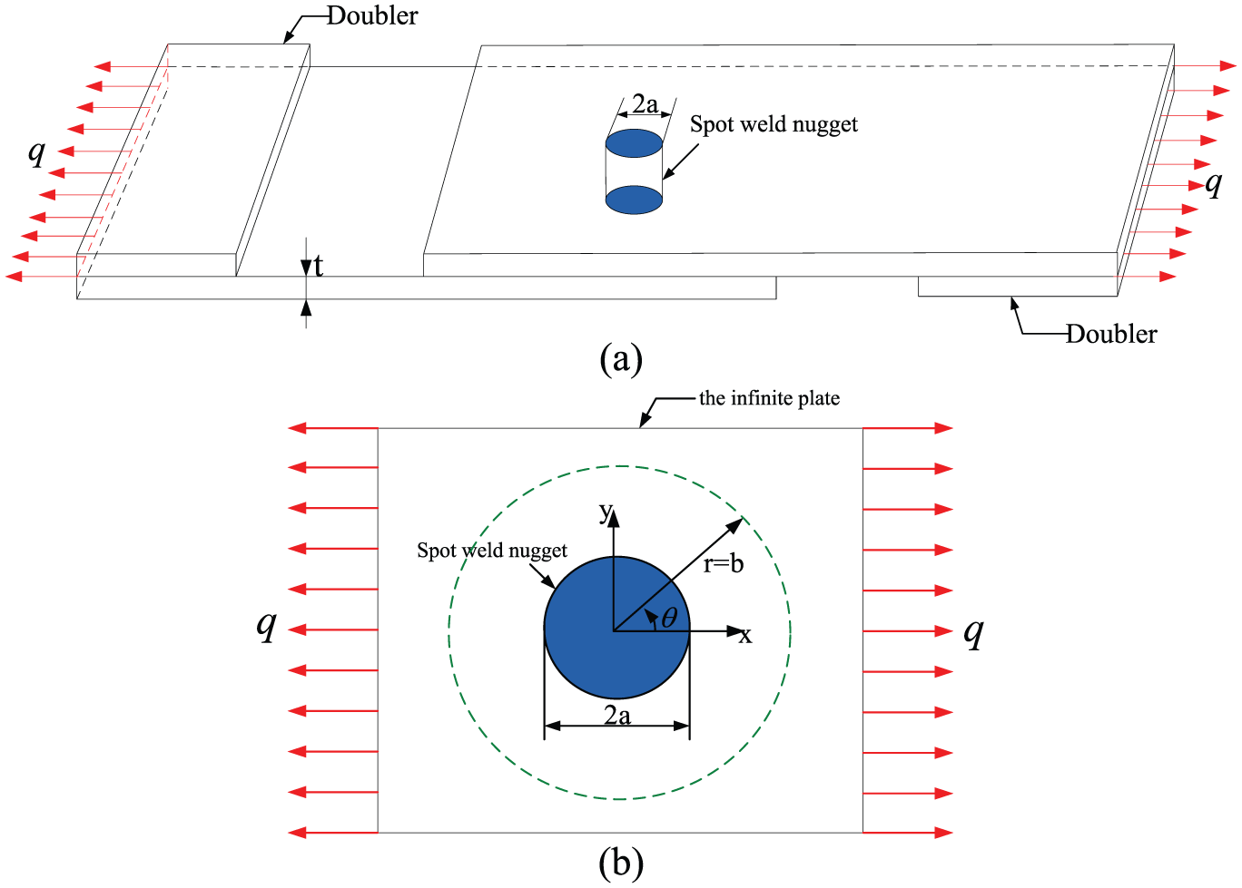
A schematic plot of (a) a lap-shear specimen subjected to a uniformly distributed force and (b) two-dimensional analytical model of a rigid inclusion in an infinite plate.
Figure 1(b) shows the 2D analytical model subjected to the uniformly distributed force q along with the two side edges of the specimens. The boundary condition is set as the tensile and shear condition which is one of the primary types of loads for a typical lap-shear specimen. The rigid inclusion represents the spot weld nugget and the infinite plate represents the upper sheet of large lap-shear specimen. In order to facilitate comparison analysis, a Cartesian coordinate system and a polar coordinate system are centered at the center of the rigid inclusion. The shear force q, marked as an arrow in the positive x-direction, represents the resultant force acting on the inclusion, which causes the rigid inclusion to move a displacement in the positive x-direction. Moreover, the 2D elastic plane stress analysis for a rigid inclusion in an infinite plate under a uniformly distributed force is carried out to understand the elastic stress distributions near the spot weld nugget in lap-shear specimen. This model is helpful to predict some useful information for analyzing yielding failure behavior or evaluating damage evolution on engineering structures jointed with spot welds.
Analytical stress solutions
Stress status in the bigger circle (marked with the dot line) is same as the plate without the spot weld nugget. Therefore, the stress boundary condition in a Cartesian coordinate system can be expressed by a 2D analytical model

The coordinate transformation expressions from a Cartesian coordinate system to a polar coordinate system can be written as follows
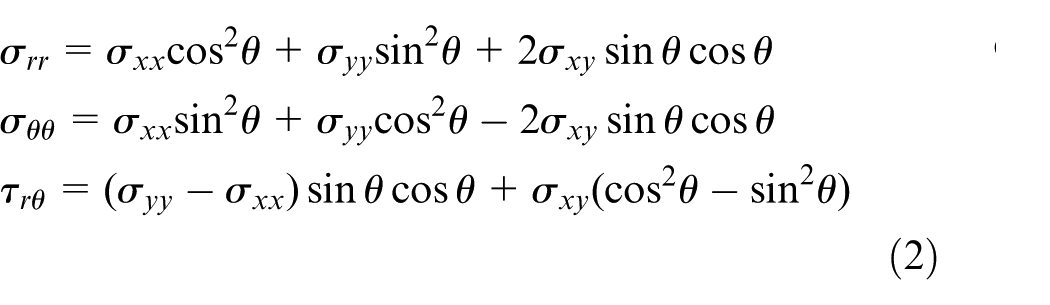
Substituting equation (1) into equation (2), the stress boundary condition is changed as follows
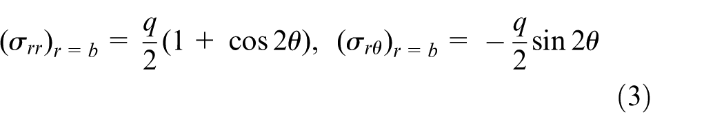
The 2D analytical model is divided into two simplified analytical models, that is, an axial-symmetry and a symmetry analytical model as shown in Figure 2(a) and (b), respectively. The axial-symmetry analytical model is subjected to uniformly tensile force q/2 along with the four side edges. Another analytical model is subjected to uniformly tensile force q/2 along with both of left and right side edges, and uniformly compression force q/2 along with both of upper and lower side edges.
Two simplified analytical models: (a) an axial-symmetry and (b) a symmetry model (only a quarter of the spot weld nugget).
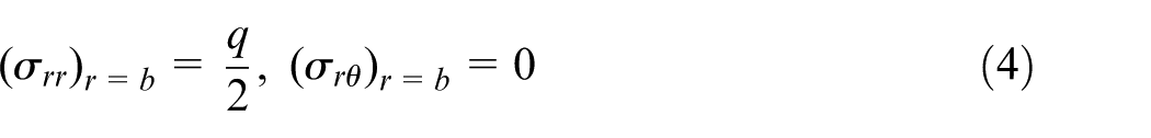
For the axial-symmetry model, the stress boundary condition changes to equation (4) in a polar coordinate system
The displacement boundary condition along the circular boundary is as follows

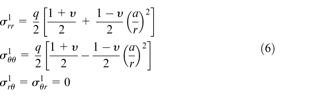
Thus, the elastic analytical stress solutions are rewritten in the following form. The detailed formula process could be referred to our work 25
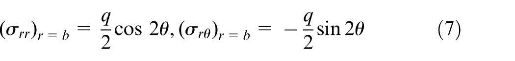
For the symmetry analytical model, the stress boundary condition is presented as follows
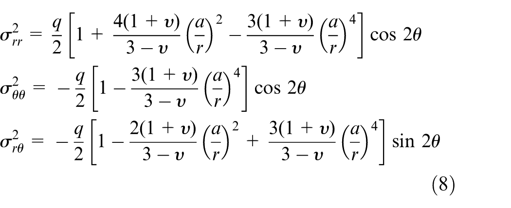
The elastic analytical stress solutions are obtained as follows
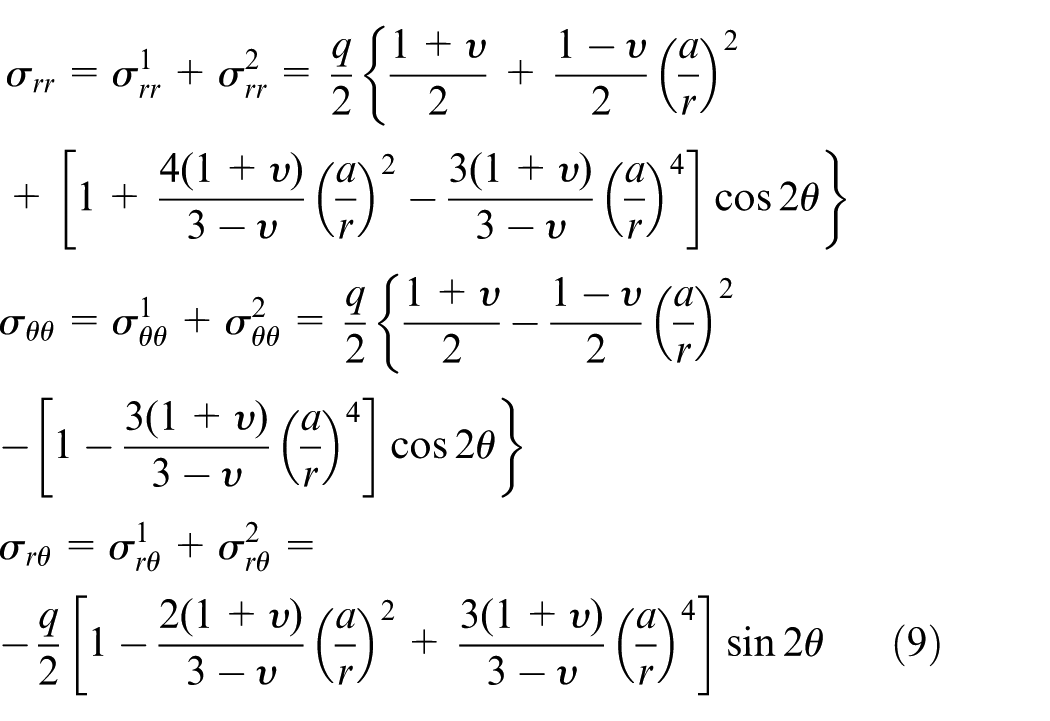
Thus, the elastic analytical stress solutions of a lap-shear specimen subjected to a uniformly distributed force q could be obtained based on the superposition principle (equation (9))
The normalized elastic analytical stress solutions including radial stress, hoop stress and shear stress can be defined as
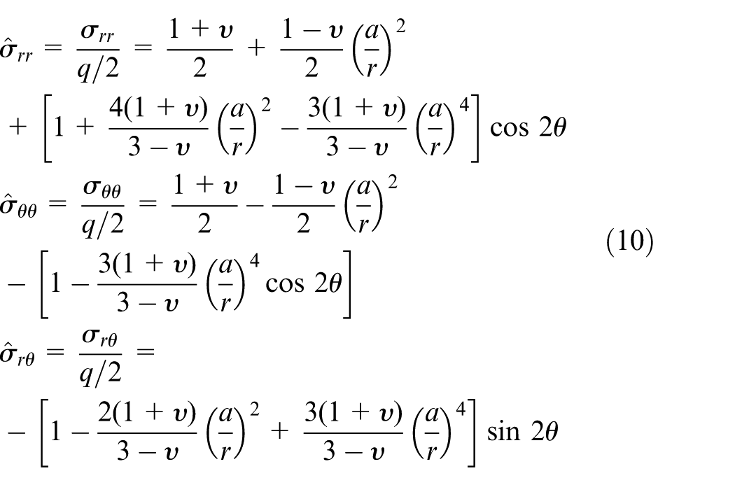
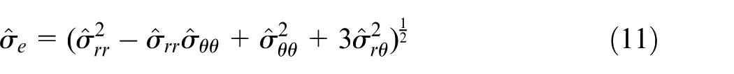
The normalized effective stress can be defined as
Stress distributions
It is obviously seen that the normalized elastic analytical stress solutions and the normalized effective stress are functions of the normalized radial distance r/a and the angles θ. However, it is relatively difficult to directly analyze the normalized elastic analytical stress solutions. Therefore, the obtained normalized elastic analytical stress solutions will be analyzed in detail based on the angular distributions at the different normalized radial distances and the radial distributions at the different angles, respectively.
Angular distributions
In this section, the angular distributions of the normalized elastic stress solutions as functions of the angles at the different normalized radial distances will be obtained and used to determine the locations of the initial yielding failure along with the different normalized radial distances.
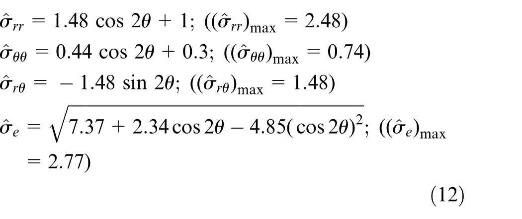
Because the elastic analytical stress solutions along the spot weld nugget are relatively special and typical significance on the locations of the initial yielding failure, the solutions at the normalized radial distance r/a = 1 are obtained and analyzed first. If the normalized radial distance and Poisson’s ratio are taken as 1 and 0.3, respectively, equations (10) and (11) will become the analytical forms explicitly as shown in equation (12). It can be evidently observed that the normalized elastic analytical stress solutions have a similar form and all the cycle periods are same π (or 180°)
Figures 3 and 4 show the angular distribution and location of normalized analytical stress solutions. It can be seen from Figures 3(a) and 4(a) that the normalized radial stress is negative in the upper small part of the plate (
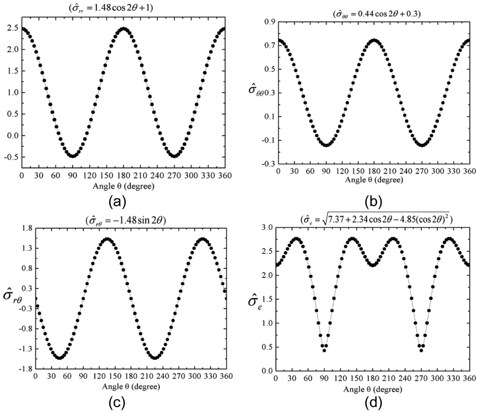
Angular distributions of the normalized analytical stress solutions: (a) the normalized radial stress
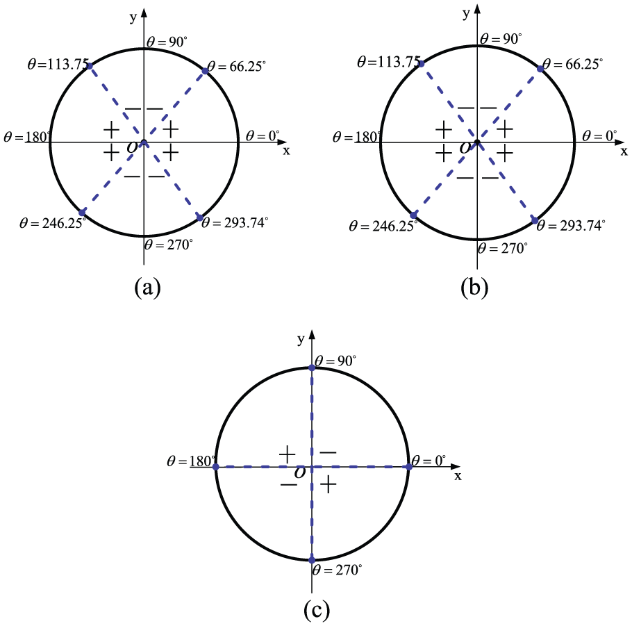
The signs of the normalized elastic analytical stress solutions at each of different locations: (a) the normalized radial stress
Table 1 shows the normalized effective stress as functions of the angles at the different normalized radial distances, and their maximum values and corresponding angular locations. It is found that the stress functions change with the normalized radial distances, and thus, the corresponding maximum values and angular location are different from each other. The angular locations of the initial yielding failure along the rigid spot weld nugget (i.e. at the normalized radial distances r/a = 1) are located at the four special angles of 38.02°, 141.98°, 218.02° and 321.98°, respectively. When the radius r expands gradually and the normalized radial distances r/a equals 1.05, the angular locations of the initial yielding failure are changed to the angles of 33.09°, 146.91°, 213.09° and 326.91°, respectively. As the radius r reaches 1.10a, the initial yielding failure is located at the four different angles of 21.35°, 158.65°, 201.35° and 338.65°. Finally, the initial yielding locations occur at the two special angles of 0° and 180°, and no longer changes.
The normalized effective stress functions and corresponding angles at the initial yielding failure locations.
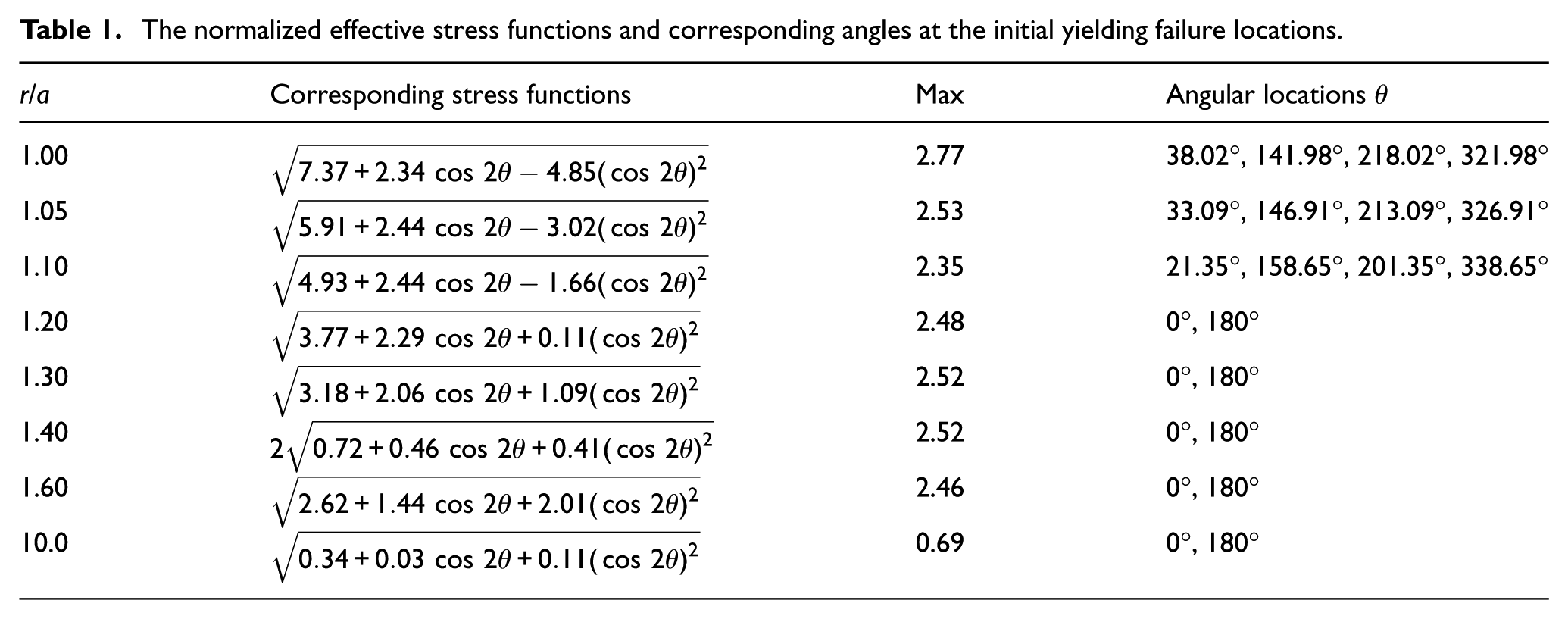
Figure 5 shows the change trend of the locations of the initial yielding failure with normalized radial distances. In order to understand the stress distributions, the angular distributions of the normalized effective stress along with the circumferential angles at the different normalized radial distances are illustrated in Figure 6. It can be derived that variation of the maximum values and the locations of the initial yielding failure are complicatedly with the normalized radial distance.
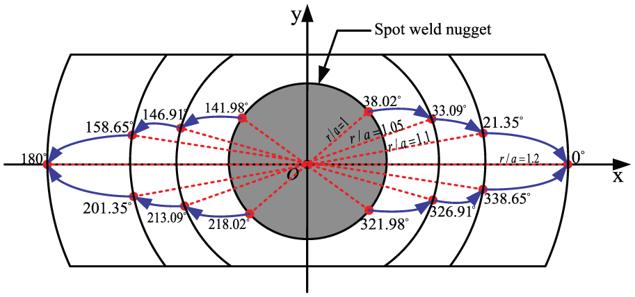
The change trend of the locations of the initial yielding failure along the different normalized radial distances r/a.
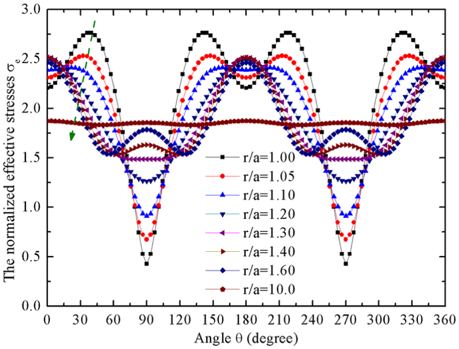
The angular distributions of the normalized effective stress along the different normalized radial distances r/a.
Radial distributions
According to the above results, the angular distributions of the normalized elastic analytical stress solutions at the different normalized radial distances r/a are so complicated that it is hard to understand the normalized elastic analytical stress solutions. Therefore, the radial distributions of the normalized elastic analytical stress solutions as functions of the normalized radial distance r/a at the different angles are investigated in this section based on radial distributions of the normalized stresses
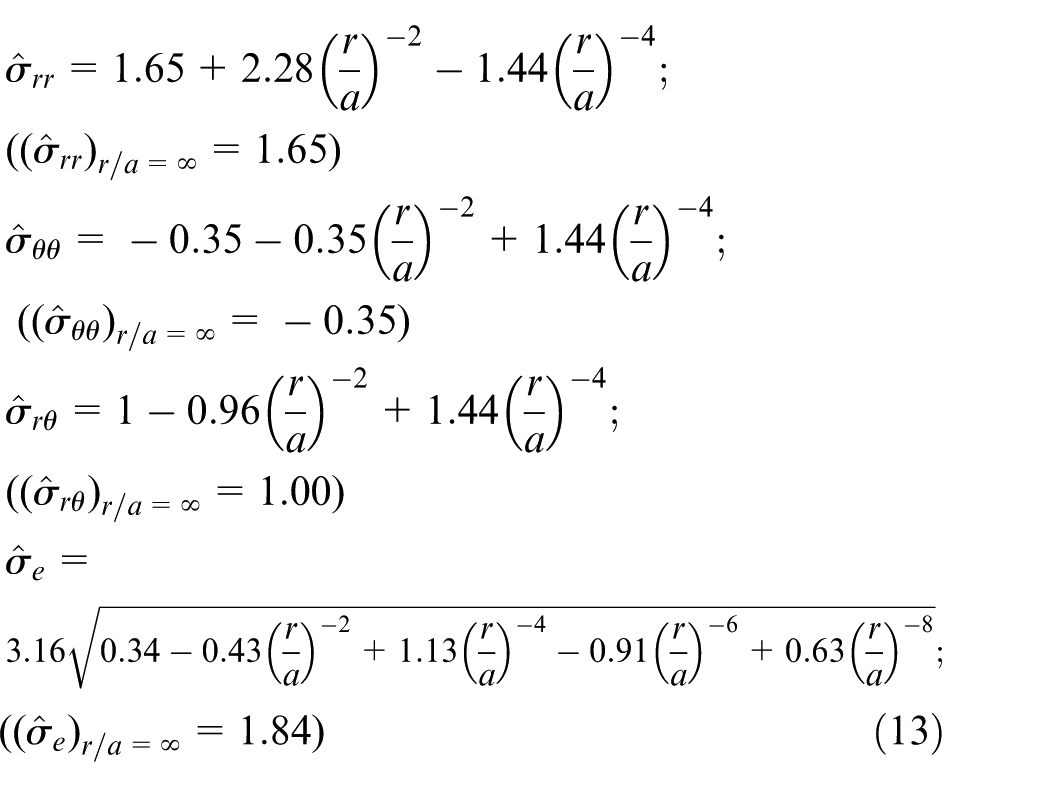
Figure 7 shows the radial distributions of the normalized stresses as functions of the normalized radial distance at different angles. It can be seen from Figure 7(a) that the normalized radial stress slightly increases first and then gradually decreases as the normalized radial distance increases, and the radial distance corresponding to the maximum normalized radial stress of 2.55 is 1.12. The location with the maximum normalized radial stress of 2.49 is significantly close to the spot weld nugget along with which the maximum normalized radial stress of 2.49 at the normalized radius r = a. According to equation (13), the normalized radial stress should approach to 1.65 as the normalized radius goes to infinity. It is found in Figure 7(b) that the normalized hoop stress sharply decreases as the normalized radial distance increases, and the normalized hoop stress should approach to −0.35 as the normalized radius goes to infinity. Figure 7(c) illustrates that the normalized shear stress sharply decreases and then gradually increases as the normalized radial distance increases. The radial distance with the minimum normalized shear stress of 0.84 is located at r/a = 1.73 in the plate. Unlike the normalized radial stress, this location is slightly a little farther from the spot weld nugget with the maximum normalized shear stress of 1.48 at the normalized radius of r = a. Figure 7(d) depicts that the normalized effective stress has a similar trend with the normalized shear stress, that is, it sharply decreases first and then gradually increases and finally turns to be stable as normalized radial distance increases. The radial distance with the minimum normalized effective stress of 1.71 is located at r/a = 2.01 in the plate. This location is far from the spot weld nugget along with which the maximum normalized effective stress of 2.75 at the normalized radius r = a. The normalized effective stress should approach to 1.84 as the normalized radius goes to infinity.
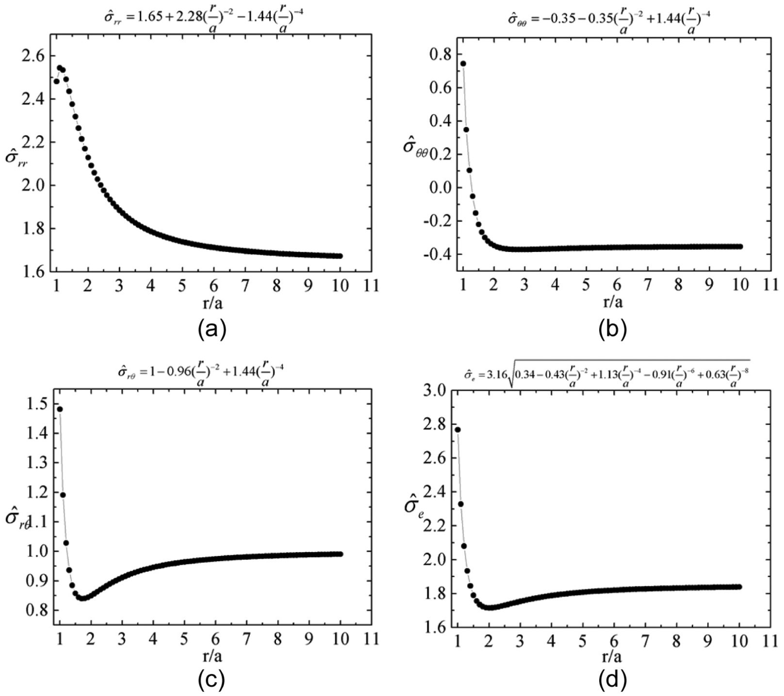
Radial distributions of the normalized stresses as functions of the normalized radial distance r/a at the different angles for the corresponding normalized stresses: (a) θ = 180°, (b) θ = 180°, (c) θ = 135° and (d) θ = 38.02°.
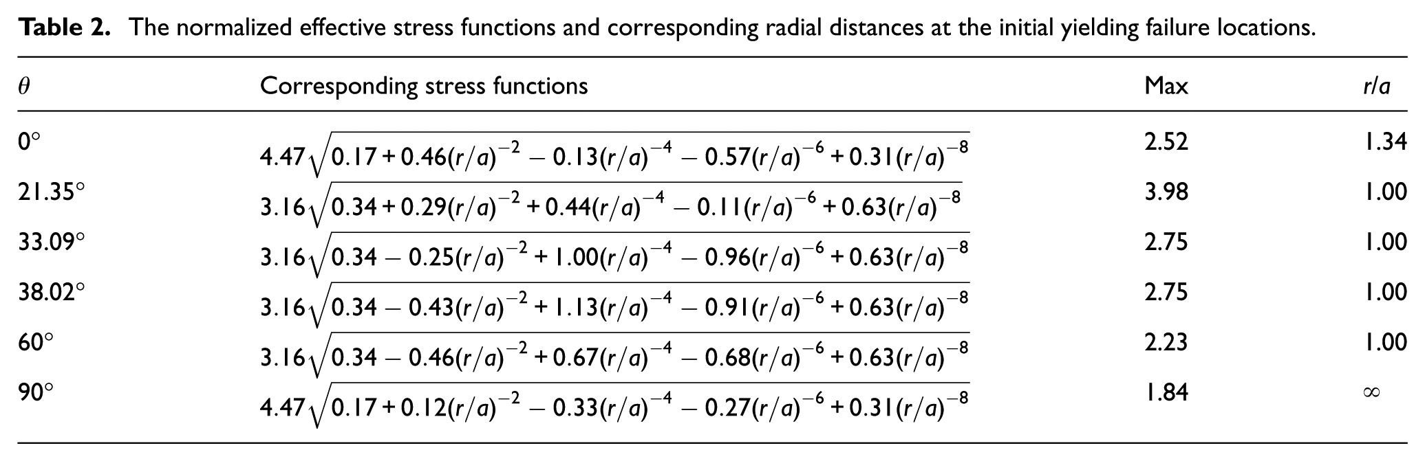
The normalized effective stress functions shown in Table 2 and the change trend of the initial yielding failure with the normalized radial distance visualized in Figure 8 are investigated to understand the effective stress distributions. It is found that the locations of the initial yielding change gradually from the normalized radial distance of 1.34 to the edges of the spot weld nugget, and finally to the infinity as the angle increases.
The normalized effective stress functions and corresponding radial distances at the initial yielding failure locations.
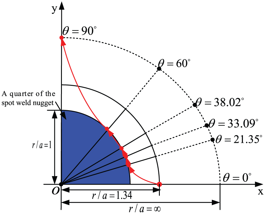
The change trend of the locations of the initial yielding near the rigid spot weld nugget along the different normalized radial distance r/a (only a quarter of the spot weld nugget).
Figure 9 shows the radial distributions of the normalized effective stress at several special angles. It can be seen that normalized effective stress slightly increases first, and then gradually decreases, and finally approaches to a constant of 1.84 at the angle of 0° as the normalized radius increases. The maximum normalized effective stress of 2.52 is located at the normalized radial distance of 1.34. The normalized effective stresses monotonically decrease at the angles of 21.35° and 33.09°, but sharply decrease first and then gradually increase at the angles of 38.02° and 60°. A special break point or rock bottom located at between the normalized radial distance of 1.0 and 1.5. The normalized effective stress monotonically increases with the normalized radial distance at the angle of 90°. Moreover, the normalized effective stress approaches to 1.84 as the normalized radial distance goes to infinity, no matter which angle is.
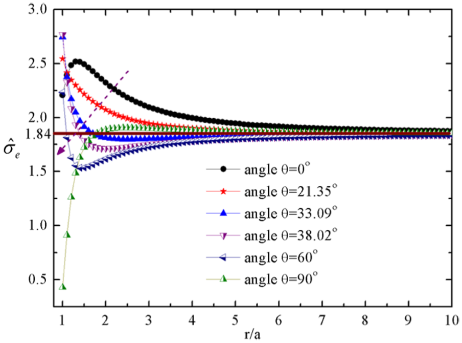
The radial distribution of the normalized effective stress at several special angles along the different normalized radial distances r/a.
Figure 10 shows the three-dimensional (3D) schematic plots of the normalized stress elastic analytical solutions based on equations (10) and (11). It can be seen from Figure 10(a)–(c) that the stress distributions are relatively simple and feasible to recognize extreme values of the normalized radial stress, hoop stress and shear stress. But for the normalized effective stress, Figure 10(d) indicates that the stress distribution is relatively complicated and difficult to identify extreme values, especially along with the spot weld nugget. This is why the angular distributions at the different normalized radial distances and the radial distributions under the different angles are presented and discussed separately. In addition, it can be found from Figure 10(d) that the normalized effective stress should approach to 1.84 as the normalized radial distance goes to infinity, no matter which angle is as mentioned above.
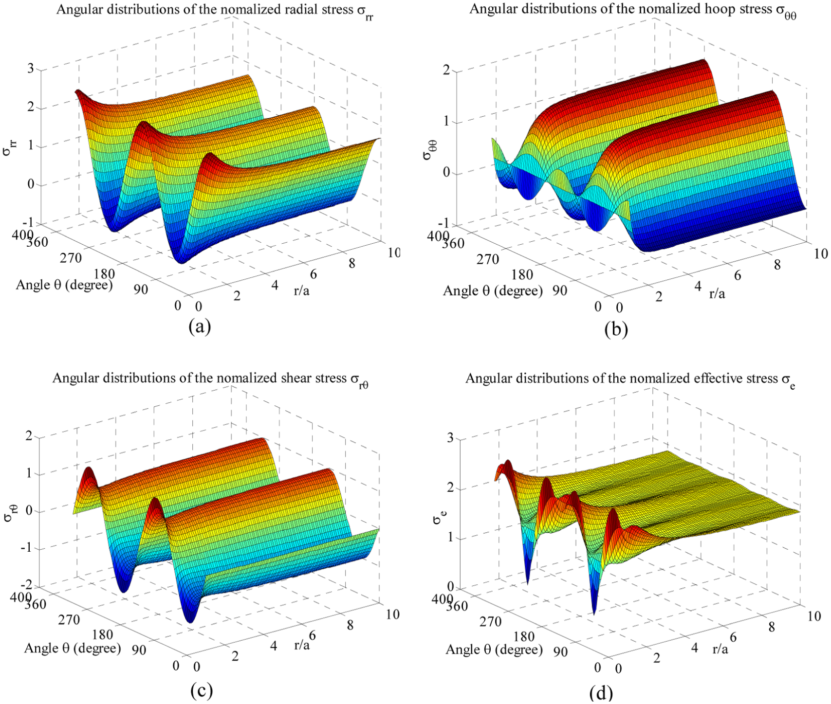
The three-dimensional schematic plots of the normalized stresses along the different normalized radial distance r/a and different angles: (a) the normalized radial stress, (b) the normalized hoop stress, (c) the normalized shear stress and (d) the normalized effective stress.
Numerical analysis
To simulate the problem shown in Figure 1(b), the finite element analysis (FEA) commercial program ABAQUS 6.10-1 is used. Meanwhile, a plate width of 128 mm and nugget radius of 3.2 mm are studied. Eight-node quadrilateral elements (plane stress elements: CPS8R) with four integration points set in each element are adopted. A finite element model is created in Figure 11, in which a spot weld nugget is fixed along the nugget circumference and a uniformly distributed tensile load q is imposed in the left and right edges of plates and stretched from the both directions. The upper and lower edges of lap-shear specimen representing the side edges of plate are set as a traction-free.
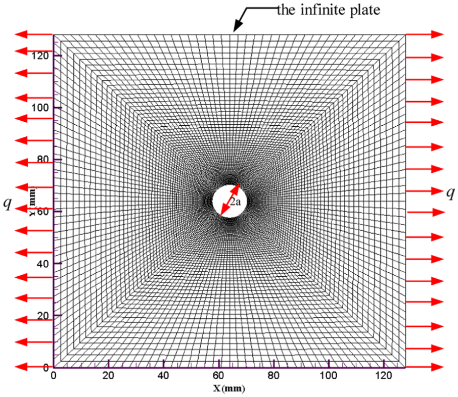
A plane stress finite element model subjected to a uniformly distributed tensile load q along the left and right edges.
Based on the analytical solutions shown in Figure 5, the initial yielding along the rigid spot weld nugget (i.e. at the normalized radial distances r/a = 1) locates at the four special angles of 38.02°, 141.98°, 218.02° and 321.98°, respectively. Therefore, if the normalized radial distances r/a and the angle are taken as 1 and 38.02°, respectively, the normalized effective stress can be calculated from equation (9) as follows

For the analytical elastic solution of DP600 base material, the normalized effective stress along the spot weld nugget must be smaller than the yield stresses of DP600. The critical initial yield stresses are 376.4 MPa for the high strength steel. Based on the yield stresses and equation (14), the material near the spot weld nugget will initiate yielding as the distributed load reaches 272.06 N/mm2.
Figure 12 compares the elastic results of FEA and the analytical solutions under distributed load q = 100 N/mm2 (smaller than 272.06 N/mm2). Overall, the numerical results and the angles corresponding to the peak Von Mises stresses are in fairly good agreement with the analytical solutions. Four peak stresses indicate that the initial yielding locations would likely occur at the four angles corresponding to the spot weld nugget.
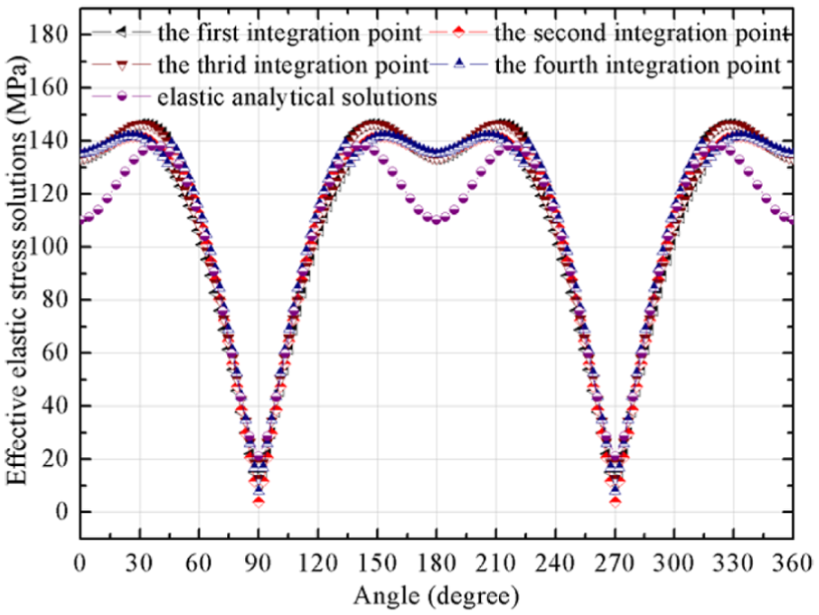
Comparisons of the elastic FEA and the elastic analytical solutions under the uniformly distributed load of q = 100 N/mm2.
Figure 13 shows the contour of Von Mises stress. It can be found that the stress distributions are rather similar in the analytical solutions (Figure 13(a)) and the numerical solutions (Figure 13(b)). In addition, the locations with peak Von Mises stresses (four points A, B, C and D) along the circumference of the spot weld nugget are also very similar to those from the analytical solutions at four specific angular locations of 38.02°, 141.98°, 218.02° and 321.98°.
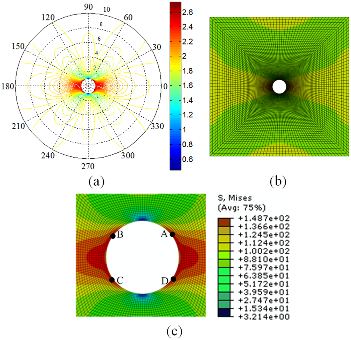
(a) Schematic plots of the normalized effective stresses in the polar coordinate system, (b) distributions of the numerically elastic Von Mises stress near the spot weld nugget and (c) enlarged distributions of the elastic Von Mises stress.
Conclusion
In this article, an elastic analytical solution is derived to study the stress distributions near the spot weld nugget in lap-shear specimens subjected to a uniformly distributed force. A Cartesian coordinate system is centered at the center of the nugget, and the shear or resultant force acting on the nugget is marked as the positive x-direction. Some remarkable conclusions are listed as follows:
The normalized radial stress and the normalized hoop stress are negative at the angle intervals between [66.25°, 113.75°] and [246.25°, 293.74°], while the normalized shear stress is negative at the angle intervals between [0°, 90°] and [180°, 270°]. The angular distribution of the normalized effective stress along the normalized radial distance is obtained and the locations of the initial yielding failure change gradually from the angles of 38.02°, 141.98°, 218.02° and 321.98° to the angles of 0° and 180°.
The radial distributions of the normalized elastic analytical stress solutions show that the locations of the initial yielding failure change gradually from the normalized radial distance of 1.34 to the circumference of the spot weld nugget, and finally to the infinity as the angle increases. The normalized effective stress could approach to 1.84 as the normalized radial distance goes to infinity.
The obtained analytical solutions are numerically validated by simulation results. The distributions of the peak Von Mises stresses along the circumference of the spot weld nugget are also very similar to those from the analytical solutions at four specific angular locations of θ = 38.02°, 141.98°, 218.02° and 321.98°. The initial yielding locations would likely occur at the four corresponding angles of the spot weld nugget.
Footnotes
Declaration of conflicting interests
The author(s) declared no potential conflicts of interest with respect to the research, authorship and/or publication of this article.
Funding
The author(s) disclosed receipt of the following financial support for the research, authorship, and/or publication of this article: The support of this work by the National Natural Science Foundation of China (51605353, U1564202) is greatly appreciated. The work was also supported by the Program for Innovative Research Team in University (IRT13087) and 111 Project (B17034).