
Abstract
For a parallel gear shaving process, the tooth flanks of a shaved work gear surface are longitudinally crowned using an auxiliary crowning mechanism. However, the flanks are only crowned in the longitudinal direction and not in the cross-profile direction so there is a natural twist on the shaved work gear surfaces. A new shaving method for double-crowning that has no natural twist in the tooth flanks on the work gear surfaces is proposed, which uses a variable pressure angle shaving cutter in a parallel gear shaving process. Three numerical examples are presented to verify the merits of the proposed shaving method. The tooth flanks are crowned in both the cross-profile and the longitudinal directions, and natural twists in the shaved tooth flanks are reduced significantly.
Keywords
Introduction
The tooth flank of a work gear is longitudinally crowned using an auxiliary crowning mechanism that rocks the work gear with respect to a moving pivot. The shaving cutter is usually meshed with the work gear on parallel axes. In this shaving process, two independent motions are required for parallel shaving: tight rotational meshing between the work gear and the shaving cutter and a traverse motion for the work gear by moving the pivot. Longitudinal crowning is achieved using the influence of an auxiliary crowning mechanism’s rocking motion. However, this method only crowns in the longitudinal direction, and the tooth flank of the shaved work gear surface is twisted. A method for double-crowning that does not have a natural twist in the tooth flanks on the work gear surface is proposed, which uses a variable pressure angle (VPA) shaving cutter in a parallel gear shaving process.
Basic mesh conditions for the involute helical gear set have been outlined in texts. 1 Previously, Daniel 2 and Pemack and Krygier 3 patented a shaving cutter that shaves a helical gear to give desired involutes at both ends and centrally on the teeth. Zhong and Qu 4 used a method that combines artificial intelligence and fuzzy logic techniques to allow on-line computer control of an axial gear shaving process, to improve the quality of workpiece gears. In 1996, Kim and Kim 5 developed a MS-Windows application program that designs shaving cutter specifications for a given shaved gear. In the same year, Koga et al. 6 studied tooth profile errors in a plunge shaving cutter that result from errors in the grinding machine setup. Miao and Koga 7 developed a mathematical model of a theoretical tooth profile for a plunge shaving cutter. Subsequently, Hsieh et al. 8 proposed a novel highly efficient method that uses a hob cutter to manufacture a shaving cutter that eliminates standard manufacturing problems, increases the efficiency of production and increases the stiffness of the shaving cutter. Other methods for the design of plunge shaving cutters that are used to manufacture modified helical gears have also been proposed.9–11 Several technologies can be used to generate the crowned gear surfaces on a shaving machine. Praeg 12 patented a method of crown finishing gears that comprises rotation of the work gear and shaving cutter in mesh at crossed axes with a relative crowning stroke between the work gear and the shaving cutter. Seol and Litvin 13 proposed a modified geometry for the involute spur and helical gears with parallel and crossed axes that are used in gear shaving, which localizes and stabilizes the bearing contact and reduces noise and vibration. More recently, Hung et al. 14 and Chang et al. 15 developed a mathematical model for a shaved gear with auxiliary crowning that takes into account both the parameters for the gear shaving machine and cutter assembly errors. Although this is still considered to be a standard pitch cylinder model, further study of the meshing point between the work gear and the shaving cutter during pitch cylinder operation was needed. Hsu and Fong 16 and Tran et al. 17 proposed a mathematical model for pitch cylinder operation for the tooth profile of a work gear that is finished by parallel shaving with an auxiliary crowning mechanism. To localize the gear tooth contact pattern and to allow perfect transmission errors, a novel double-crowned tooth geometry is used ease-off topography for a spiroid gear that was manufactured using a precision casting process. 18 Ling et al. 19 proposed two gear-grinding techniques to improve pitch deviations in ultra-precision gears: the offset-compensated technique and the neighbour-tooth translocation technique. Recently, Tran et al.20,21 proposed a methodology for finish-hobbing of twist-free tooth flank of helical gears for longitudinal tooth crowning by setting the hob’s diagonal feed motion as a second-order function of the hob’s traverse movement and using a dual-lead hob cutter wherein the pressure angle changes in its longitudinal direction. Wang et al. 22 presented a milling method and a milling principle for generating a spur face gear using a five-axis computer numerical control milling machine. Using the milling principle, a mathematical model of the milling cutter that is used to generate a spur face gear was established, and the design parameters of the cutter were determined.
This article proposes a mathematical model of a double-crowned tooth flank surface that is generated by applying an auxiliary crowning mechanism’s rocking motion and a VPA shaving cutter in a parallel shaving process. The numerical results show that the tooth flank of the shaved work gear is crowned in both the cross-profile and the longitudinal directions and it is free of natural twist.
Mathematical model of a VPA shaving cutter
The profile of the generating surface for a standard shaving cutter is the same as that for a standard helical gear that is generated using a standard rack cutter. To eliminate the natural twist in the tooth flank on a helical gear surface, the tooth surface of the standard rack cutter is modified by changing the pressure angle in the profile and longitudinal directions, as shown in Figure 1. The position vector and unit normal vector for the rack cutter’s right-hand side (R.H.) profile are expressed in the coordinate system,
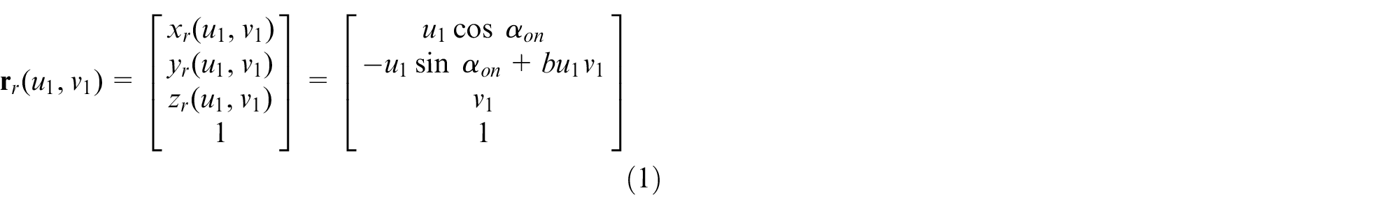
and

where
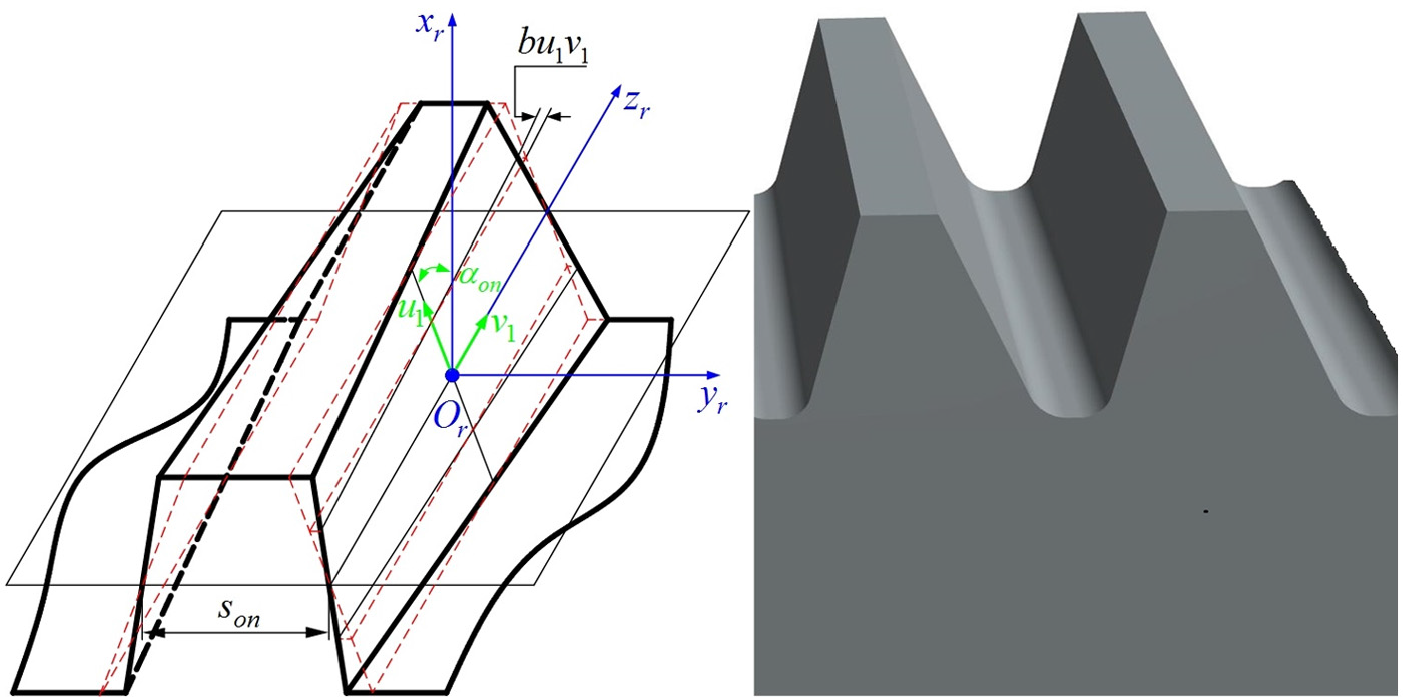
Surface parameters for the VPA rack cutter.
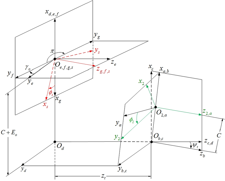
The schematic generation mechanism for the shaving cutter is shown in Figure 2, wherein the coordinate systems
and
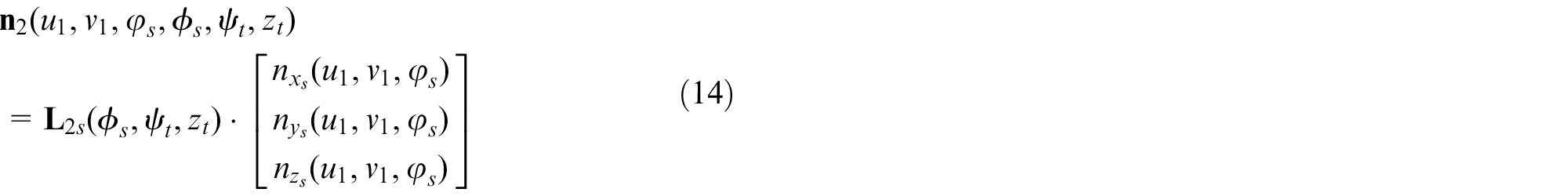
where
and
The coordinate systems for generating the surface of a VPA shaving cutter.
According to the theory of gearing, the equation for meshing between the R.H. rack cutter surface and the left-hand side (L.H.) shaving cutter surface is given by

The tooth profile and its unit normal to the VPA shaving cutter are defined using equations (3), (4) and (6). The locus tooth profile and its unit normal to the standard shaving cutter are determined by setting the coefficient,
A mathematical model of a crowned work gear that is shaved using an auxiliary crowning motion
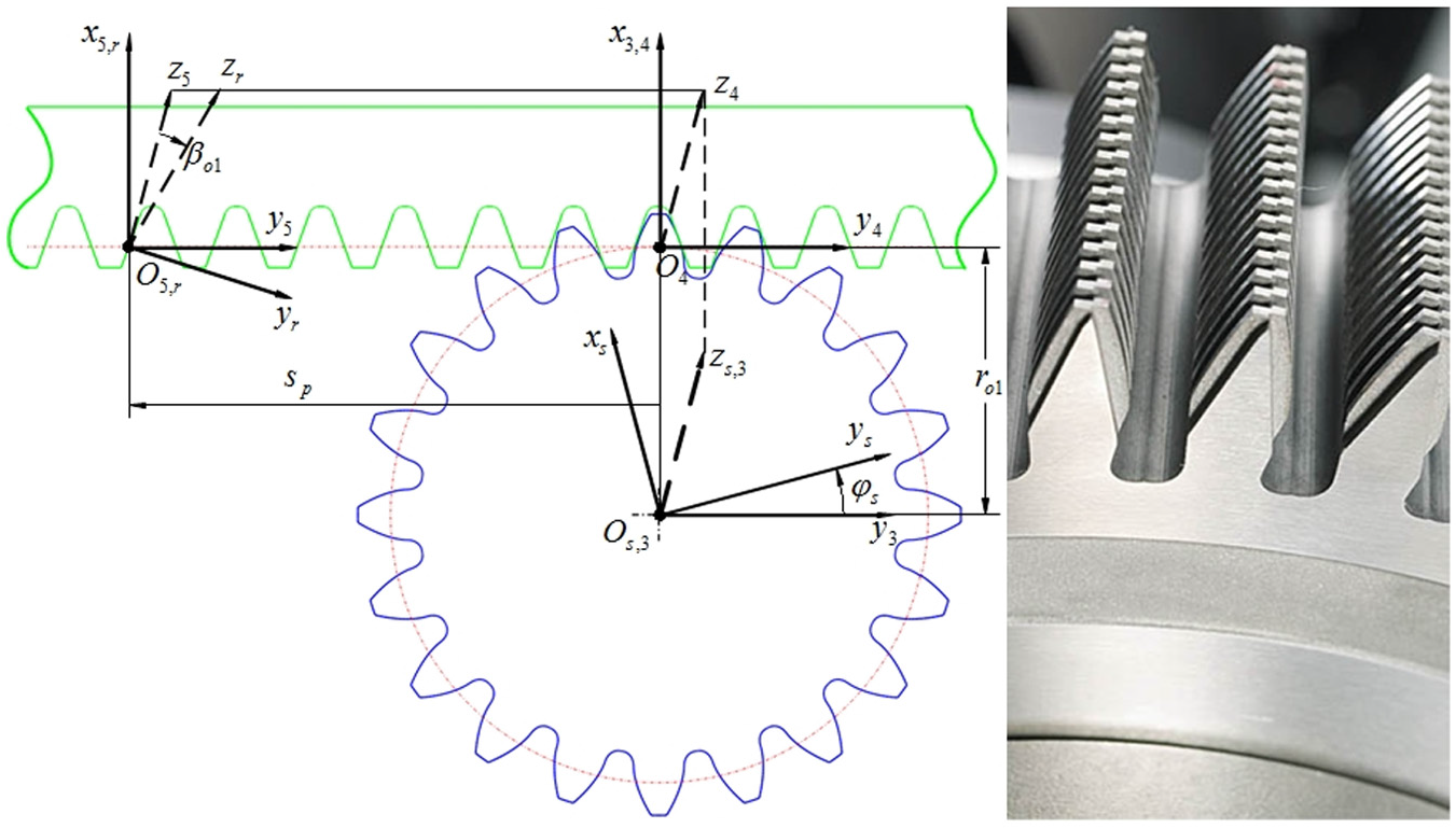
A model parallel gear shaving machine and its coordinate systems for the parallel gear shaving process using an auxiliary crowning motion are shown in Figures 3 and 4, respectively. The coordinate systems
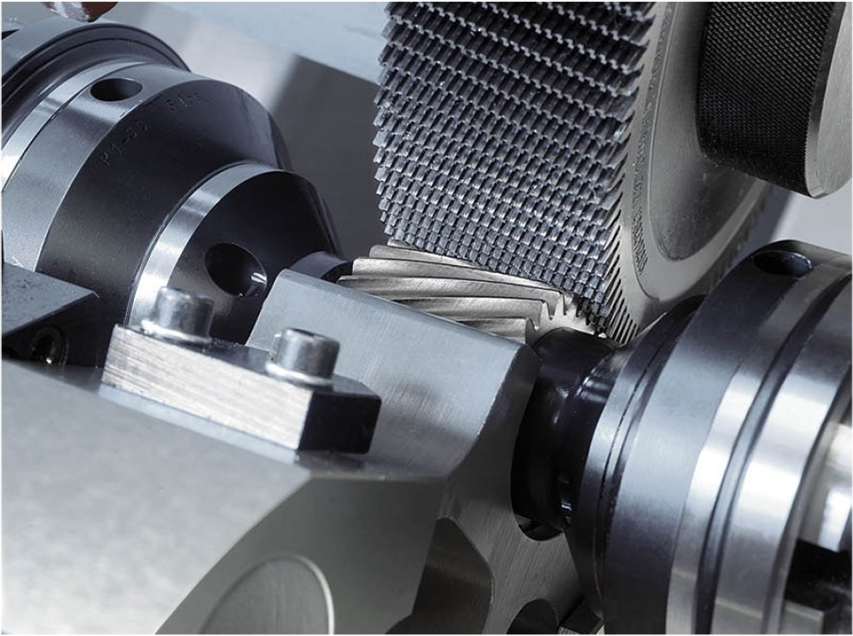
A picture of a parallel gear shaving machine.
The coordinate systems for a parallel gear shaving machine.
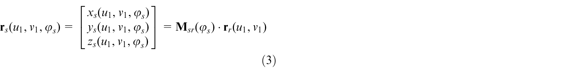
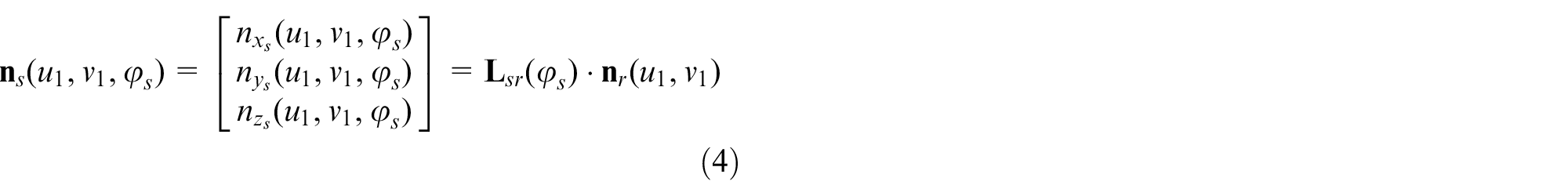
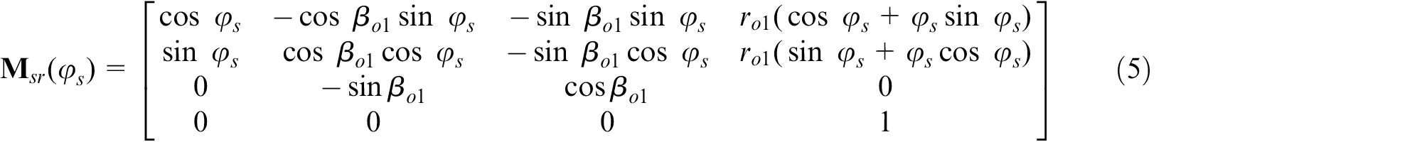
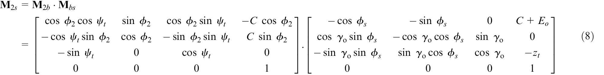
Using the homogeneous coordinate transformation matrix equation from coordinate system

where
The tooth flank of the work gear is longitudinally crowned using a crowning mechanism with an auxiliary rocking motion, and its parameters are as shown in Figure 5. The auxiliary crowning mechanism’s crowning angle,

where the distance

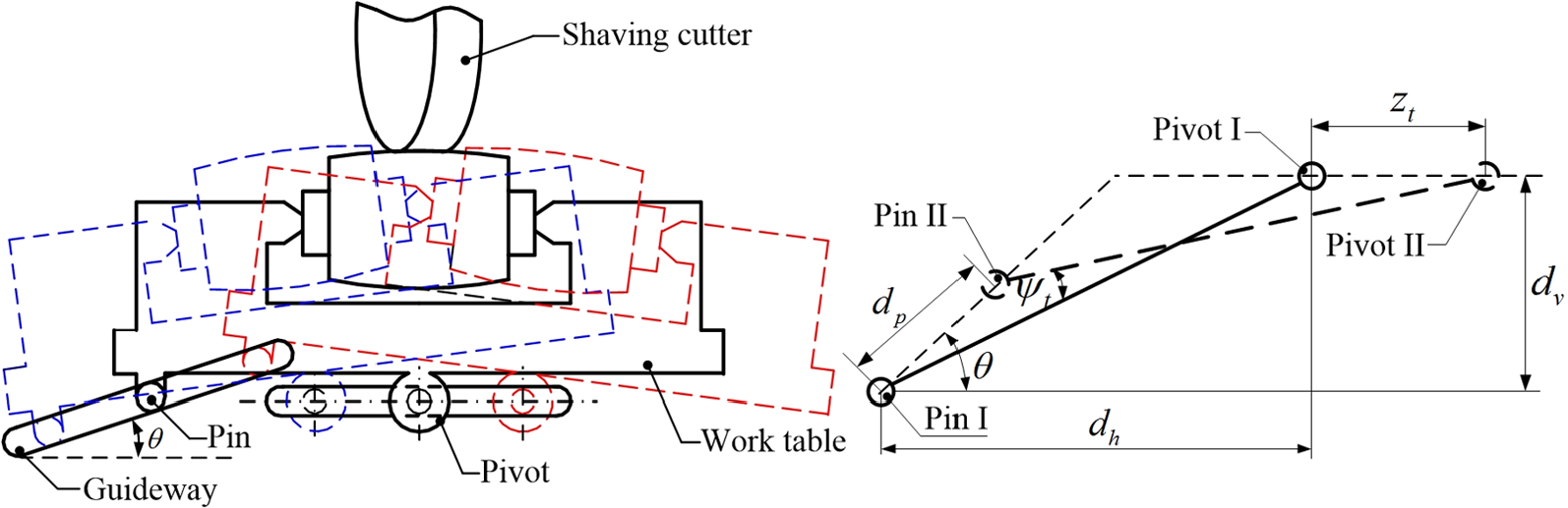
The auxiliary crowning mechanism and its parameters.
The rotational angle between the shaving cutter and the work gear is
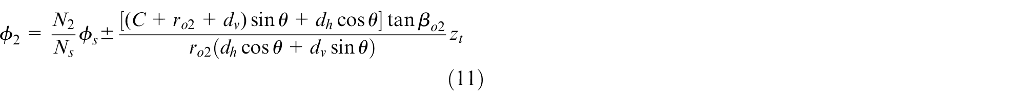
(+ sign for the R.H. and − sign for the L.H.), where
A parallel gear shaving process with an auxiliary crowning motion has two independent parameters,

and

where
The matrix
A schematic diagram of the process to produce a double-crowned tooth flank with no natural twist on the shaved work gear surface is shown in Figure 6. The initial parameters for the work gear, the shaving cutter and the shaving process are listed in Table 1. The locus and the unit normal vectors for the shaving cutter are defined for a suitable VPA coefficient
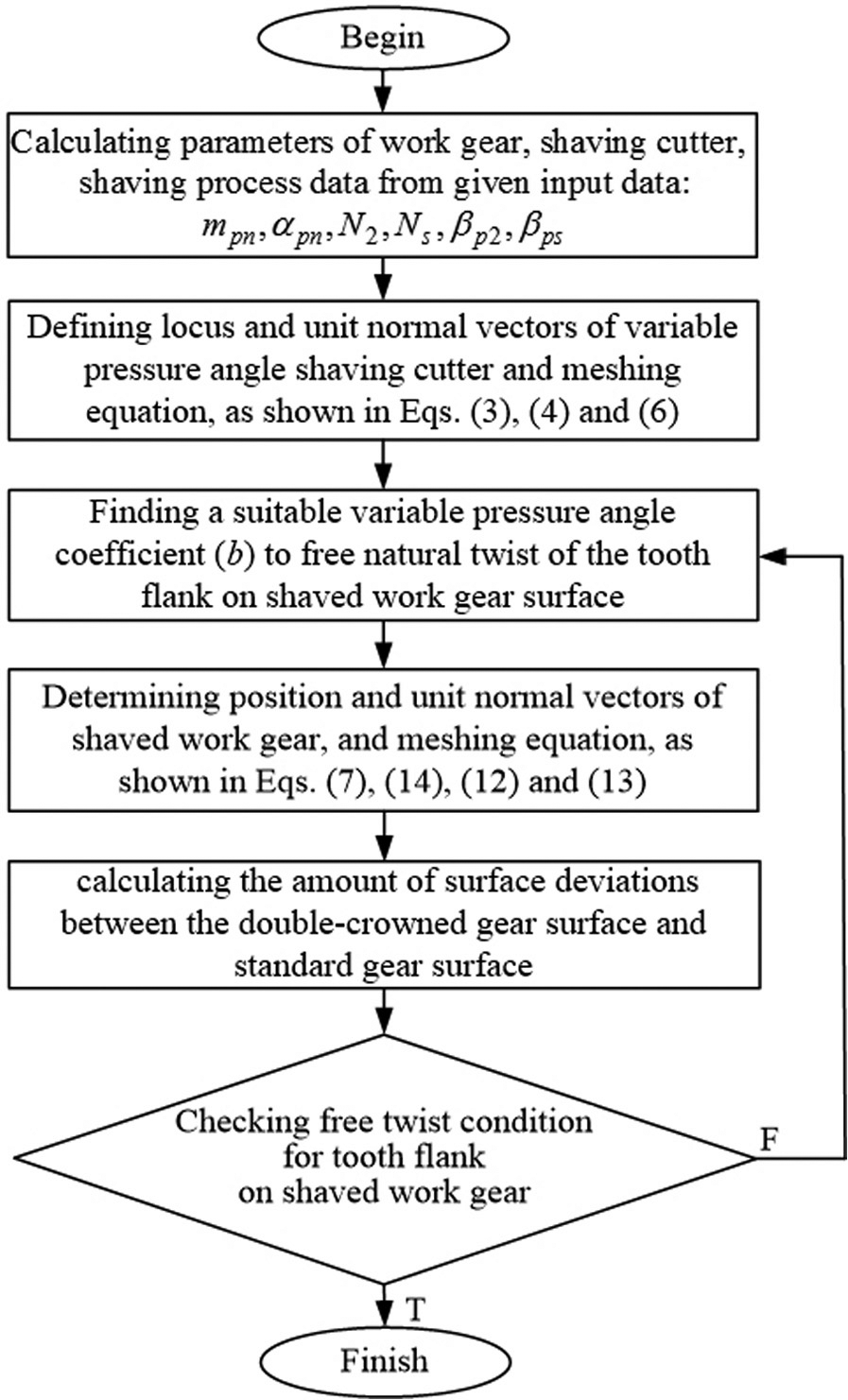
A schematic diagram for double-crowning with no natural twist for tooth flanks on work gear surfaces.
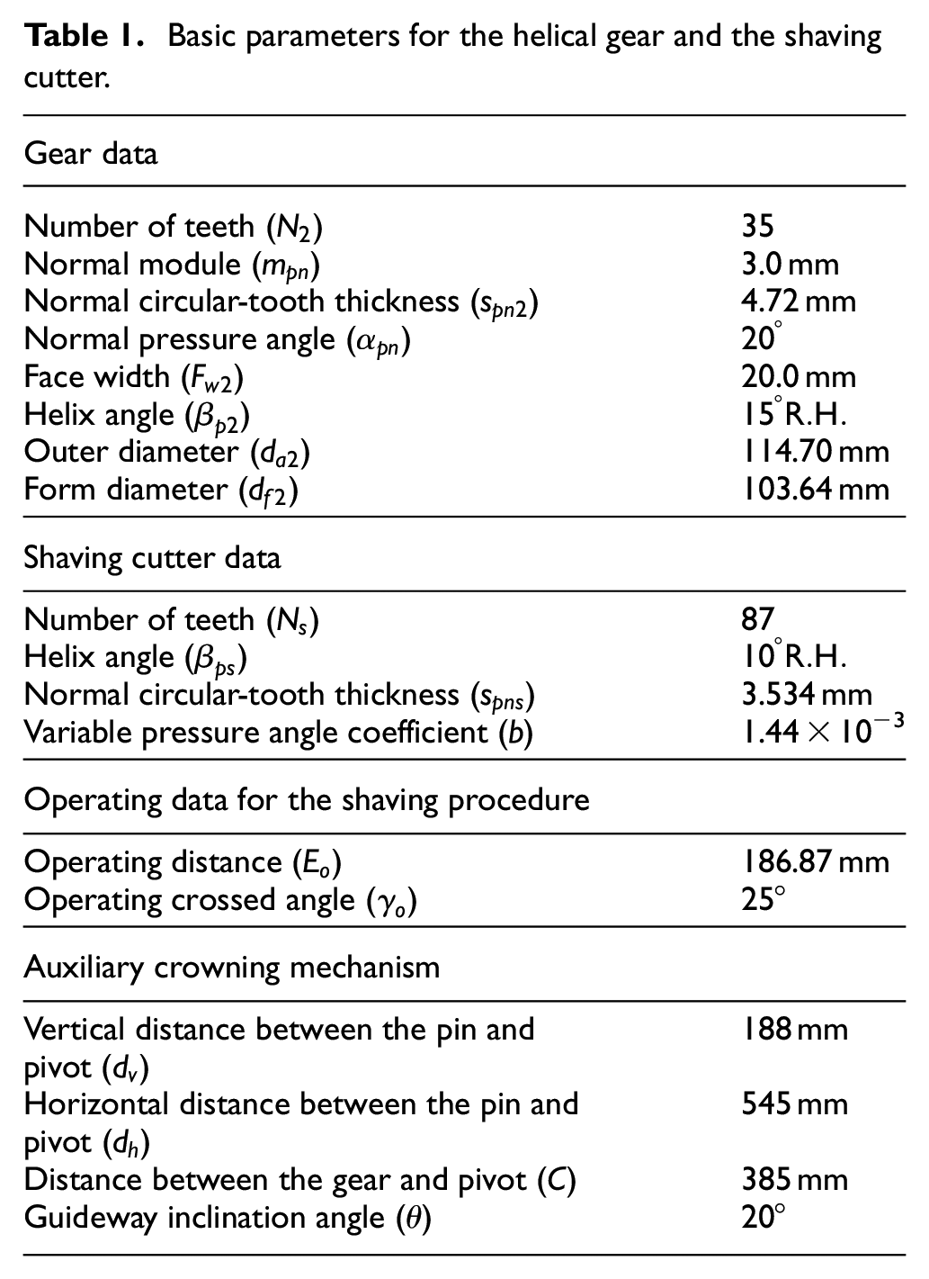
Basic parameters for the helical gear and the shaving cutter.
Numerical examples and discussion
Example 1
To determine the efficiency of the proposed double-crowning method, the tooth surface topographies of the double-crowned helical gear were simulated and compared for the two types of cutters used: a standard shaving cutter and a VPA shaving cutter. The basic data for the work gear and the shaving cutter are given in Table 1.
The degree of twist in the tooth flank for the two double-crowned work gear surfaces is measured using two indices: the maximum tooth flank twist
The longitudinal and cross-profiles of the crowned work gear surface are shown in Figure 7. Figure 7(a) shows that the tooth flanks of the work gear are crowned in the longitudinal direction for both the standard and the VPA shaving cutters. However, Figure 7(b) shows that tooth flanks for the work gear are only crowned in the profile direction when a VPA shaving cutter is used in the shaving process.
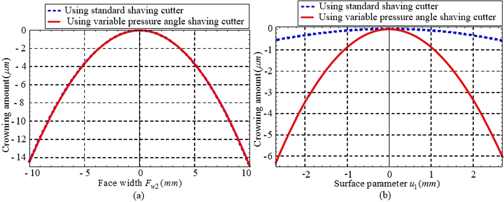
The longitudinal and cross-profiles for a crowned work gear surface: (a) longitudinal profile at operating circle and (b) cross-profile at mid-section of face width.
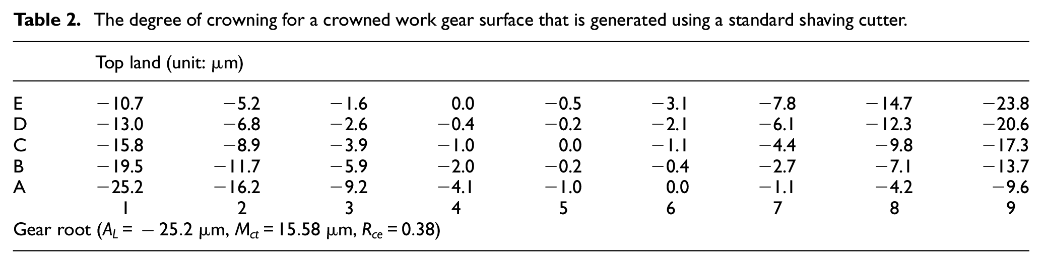
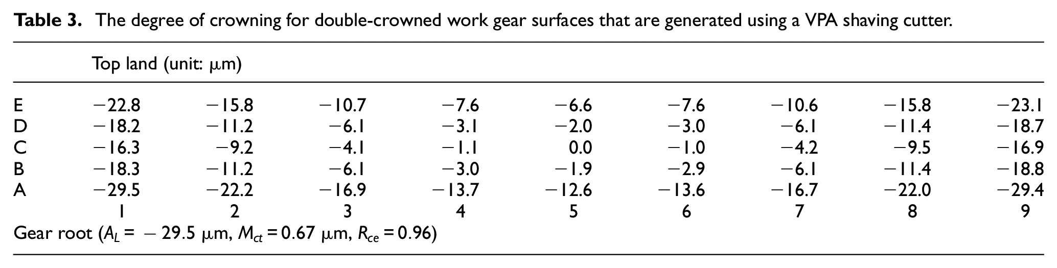
The tooth surface topographies for the proposed crowned helical gear are shown in Tables 2 and 3 and in Figures 8 and 9. Using the same guideway inclination angle (
The degree of crowning for a crowned work gear surface that is generated using a standard shaving cutter.
The degree of crowning for double-crowned work gear surfaces that are generated using a VPA shaving cutter.
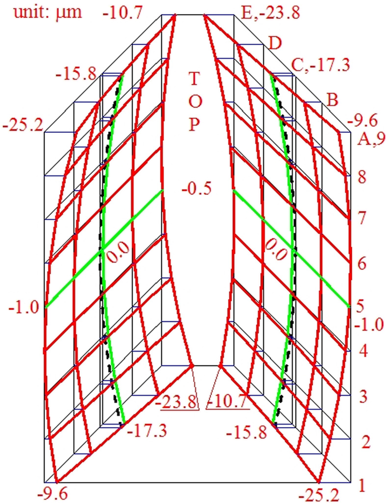
The topography of a longitudinally crowned work gear that is generated using a standard shaving cutter.
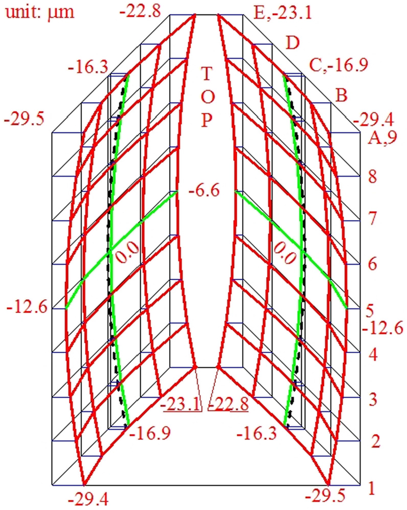
The topography of a double-crowned work gear that is generated using a VPA shaving cutter.
Example 2
This example shows the effect of the VPA coefficient

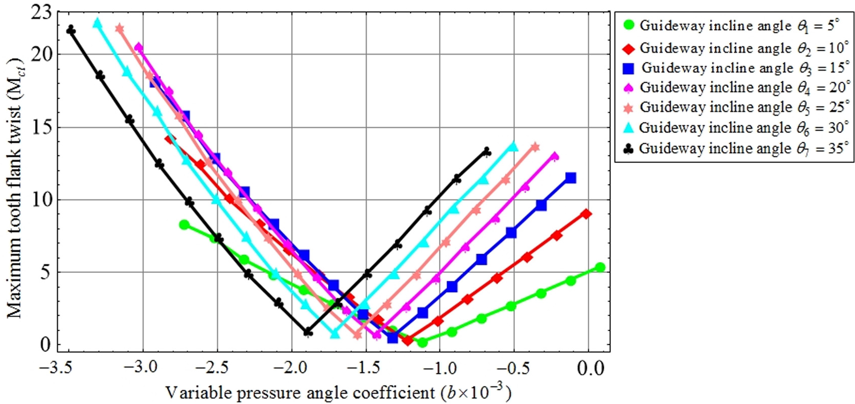
The effect of the variable pressure angle coefficient on the maximum twist in the tooth flank
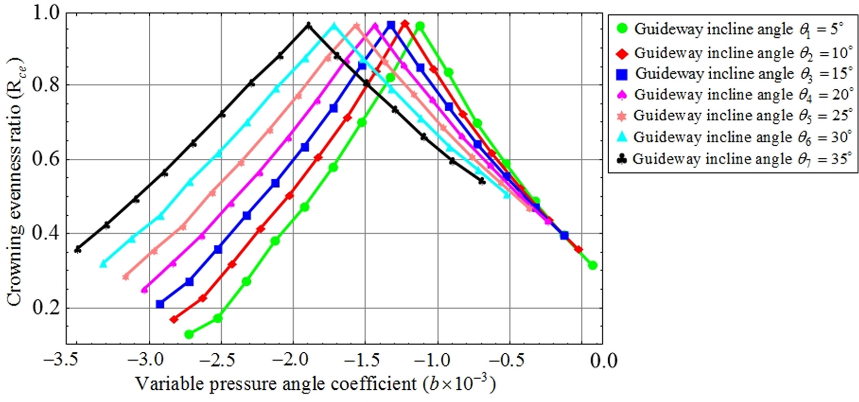
The effect of the variable pressure angle coefficient on the longitudinal crowning evenness ratio
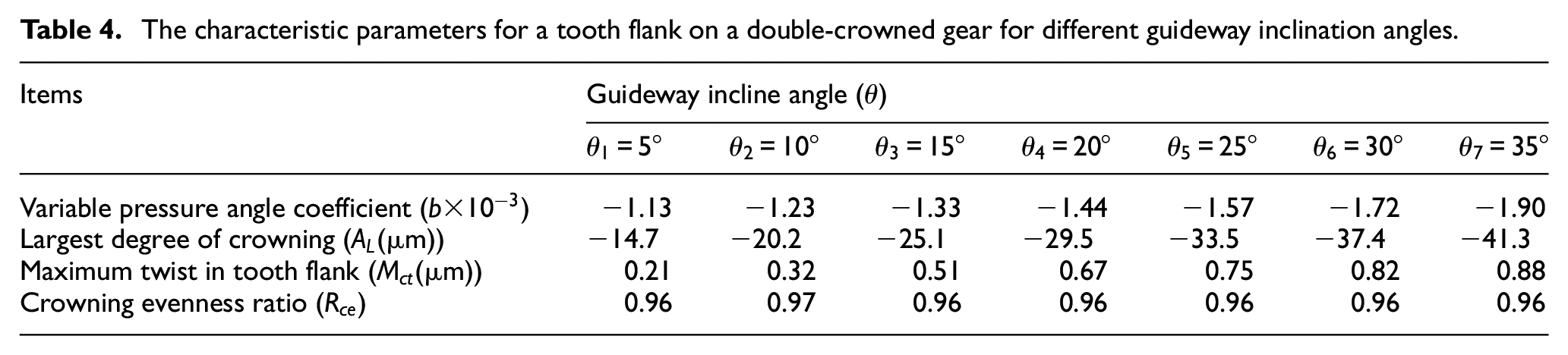
The characteristic parameters for a tooth flank on a double-crowned gear for different guideway inclination angles.
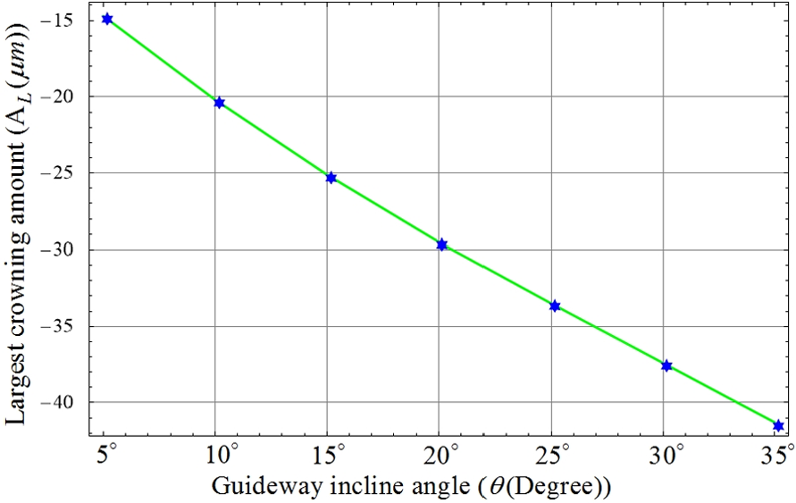
The relationship between the greatest degree of crowning and the guideway inclination angle.
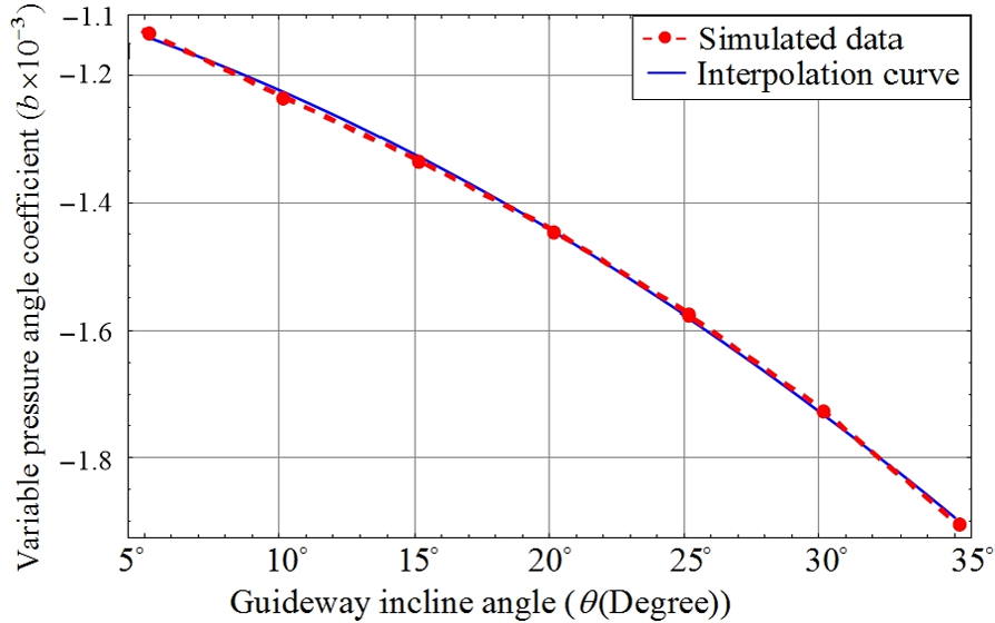
The relationship between the variable pressure angle coefficient and the guideway inclination angle.
Figure 13 shows that the curve for this interpolation function (solid line) is very close to that for the simulated data (dashed line). Therefore, it is easy to determine a VPA coefficient that corresponds to a guideway inclination angle using equation (15).
Example 3
This example determines the relationship between the VPA coefficient (b) and the helix angle of the shaving cutter

The characteristic parameters for the tooth flank on a double-crowned gear for shaving cutters with different helix angles.
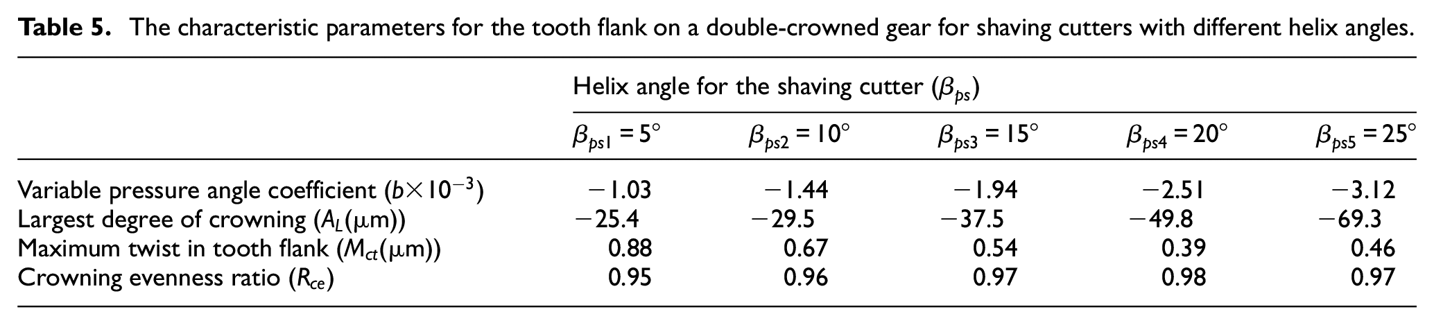
Equation (16) allows a VPA coefficient that corresponds to a helix angle for a shaving cutter to be determined.
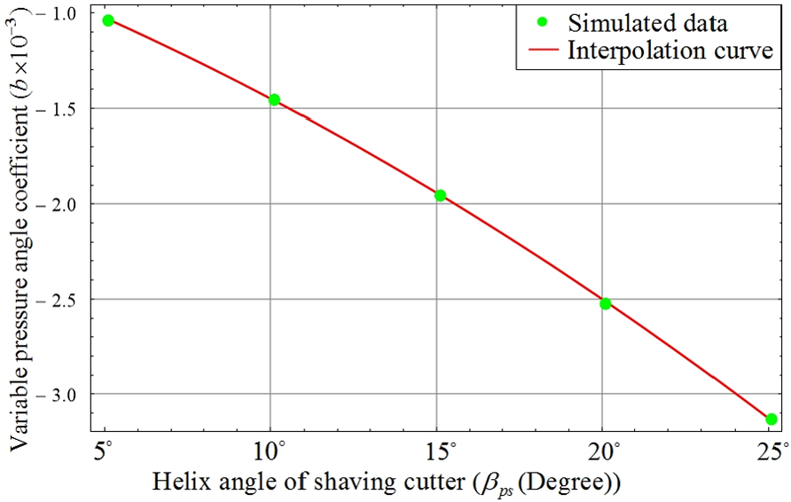
The relationship between the variable pressure angle coefficient and the helix angle for a shaving cutter.
Conclusion
A mathematical model is constructed for double-crowned tooth flanks for a shaved work gear that uses a VPA shaving cutter. The tooth flanks of the work gear are crowned in both the cross-profile and longitudinal directions. The simulated results allow conclusions to be drawn, as follows:
The natural twist in the tooth flanks for a double-crowned work gear surface that is generated using a VPA shaving cutter is much less than that when a standard shaving cutter is used.
The effect of the VPA coefficient on the maximum twist in the tooth flank and the longitudinal crowning evenness ratio for seven different guideway inclination angles is nonlinearly dependent on the VPA coefficient, as shown Figures 10 and 11.
The greatest degree of crowning is almost linearly dependent on the guideway inclination angle, but the VPA coefficient is nonlinearly dependent on the width of the face of the work gear, as shown in Figures 12 and 13 and equation (15).
The VPA coefficient is slight nonlinearly dependent on the helix angle for the shaving cutter, as shown in Figure 14. This is easily determined using equation (16).
Footnotes
Appendix 1
Declaration of conflicting interests
The author(s) declared no potential conflicts of interest with respect to the research, authorship and/or publication of this article.
Funding
The author(s) disclosed receipt of the following financial support for the research, authorship, and/or publication of this article: The authors are grateful to the Ministry of Science and Technology of Taiwan (R.O.C.) for the financial support through project numbers: MOST 104-2221-E-035-087 and MOST 104-2221-E-008-007.