
Abstract
The ever-increasing complexity in manufacturing systems caused by the fluctuating customer demands has highly affected the contemporary shop-floors. The selection of the appropriate cutting parameters is becoming more and more challenging due to the increasing complexity of products. Until now, the knowledge of the machine operators concerning the modification of the machining parameters and the monitoring information is not sufficiently exploited by the optimization systems. Web and Cloud technologies together with wireless sensor networks are required to capture the shop-floor data and enable the ubiquitous access from multiple IT tools. For addressing these challenges, this research work proposes a Cloud-based, knowledge-enriched framework for machining efficiency based on machine tool monitoring. More precisely, it focuses on the optimization of the machining parameters and moves through an event-driven optimization algorithm, utilizing the existing machining knowledge captured by the monitoring system. Based on the features of a new part, a similarity mechanism retrieves the cutting parameters of successfully executed past parts that have been machined. Afterwards, the optimization module, using event-driven function blocks, adapts these parameters to efficiently optimize the moves and the cutting parameters. The monitoring system uses a wireless sensor network and a human operator input via mobile devices. A case study from the mould-making industry is used for validating the proposed framework.
Introduction
In modern manufacturing systems, a considerable amount of knowledge regarding products and processes is generated, and remains confined to a specific machine tool operator.1,2 The capturing of this past knowledge and the reuse of it during the operational phase can improve the manufacturing system performance. 3 The accurate machining time and the selection of the cutting parameters are both becoming more and more challenging, particularly in the production of engineered-to-order products. In this type of manufacturing industry, the production and the operational phase of the system mainly rely on the machine operator’s knowledge. 2 In today’s competitive manufacturing environments, a key factor for company’s profitability is the adaptability to changes and the quick responsiveness to customer needs. Moreover, the communication among the different IT tools of a company can lead to a common information flow capable of providing meaningful information. Cloud Computing acts as an enabler in this communication, changing the traditional business model. Cloud Manufacturing, namely, the application of Cloud Computing strategies in the manufacturing sector, 4 enables the access of information and services from a variety of sources, thus facilitating the optimization of the overall production.5–7 Small and Medium enterprises can greatly benefit from this new industrial revolution since Cloud Manufacturing enables them to gain access to manufacturing data and software that they might not have been able to access in the past.
In addition to the Cloud technology, advanced monitoring systems capable of capturing the knowledge of the operational phase and addressing the dynamic environment of the production are necessary. 8 Moreover, shop-floor awareness and actual machining time of tasks can enhance decision-making during the production phase.
Furthermore, one of the challenges in modern manufacturing systems is caused by the increased product demand, leading to a need of high production rates while, at the same time, keeping low production costs. The selection of the optimum cutting parameters which minimize the production costs and maximize the production rate is essential for the increase of the overall efficiency of production systems. This has to be achieved with the minimum amount of cutting trials since this would lead to waste of material, energy, and time. This article proposes a Cloud-based, knowledge-enriched system for increasing machining efficiency based on machine tool monitoring. The proposed framework consists of a monitoring system, a knowledge-reuse mechanism, and an optimization system deployed in a Cloud platform in order to enable collaboration and ubiquitous data access among the systems.
The remainder of this article is organized as follows: section ‘State of the art’ reviews the current state of the art. Section ‘System architecture’ presents the structure of the proposed system. Section ‘Monitoring system’ shows the details of the monitoring system, followed by the knowledge-reuse mechanism and the optimization service presented in sections ‘CBR engine and similarity mechanism’ and ‘Optimization system’, respectively. Section ‘Development of the Cloud-based platform’ exhibits the details of the developed Cloud platform, and section ‘Case study and results’ demonstrates a case study of the proposed system. Finally, section ‘Conclusion and future work’ summarizes the research contributions and points out further work.
State of the art
Modern manufacturing dictates the evolution of manufacturing systems to meet the needs of the new production models that target highly customized products, produced in small lots. Subsequently, to trace the unpredicted circumstances that occur in shop-floors and to efficiently adapt to changes, the application of real-time monitoring systems has become a necessity.
The evolution of computer science and embedded technologies enables the extensive application of real-time monitoring systems. A dedicated review on monitoring systems for machining operations has been performed by Teti et al. 8 The authors specified that a monitoring systems need to be robust, reconfigurable, reliable, intelligent, and inexpensive in order to keep up with the increasing requirements for flexible manufacturing systems. Existing monitoring techniques employ various sensors based on different signals, mainly vibration, acoustic, and temperature signals, with the purpose of performing condition monitoring. 9 Monitoring techniques based on current or power measurements are rarely reported for the purposes of condition identification of cutting tools or machine tool components. 10 However, for the purpose of identifying machine status and availability, current and power measurements provide accurate and discrete results and, therefore, constitute ideal cost-effective candidates.11,12
The application of monitoring devices in the shop-floor for tracking the availability of machine tools results in an adaptive holistic scheduling has been introduced by Mourtzis et al.13,14 The framework is introduced in five layers, that is, the machine monitoring, the data preparation and diagnostic engine, the prediction engine, the visualization of results and actions, and the maintenance planning and adaptive scheduling of the system. Some distinctive work has been performed by previous literature on the subject of machining time estimation for computer numerical control (CNC) machine tools. It has been identified that the machining time estimation is still based on simple algorithms enhanced with factors derived from experience. 15 In this topic, Liu et al. 16 used a methodology that integrates the part geometry, the process plan, the machine characteristics, and the numerical control (NC) program in order to achieve an average estimation error of 3.6%. By introducing a variable, called machine response time (MRT), Coelho et al. 17 took into consideration the machine potential while estimating the actual machining time in the case of milling free-form geometries with a high feed rate. Nevertheless, the aforementioned systems do not utilize feedback from the real machining process, which is a field under investigation for this study.
Taking into account the variety and the heterogeneity of the sources that are employed by monitoring systems, information fusion techniques are used for the extraction of meaningful information. 18 Sensor-level fusion, feature-level fusion, and decision-level fusion are classified as 19 information fusion techniques. In the domain of the decision-level fusion, the Dempster–Shafer (DS) theory of evidence 20 is mostly used. 21 To enhance the performance of information fusion, it can be paired with multi-criteria decision-making (MCDM) processes, as in the work of Tapoglou 12 and Awasthi and Chauhan, 22 where the DS theory of evidence is used in conjunction with the analytic hierarchy process (AHP). The AHP 23 is commonly chosen among other MCDM methods, since it reflects the relative weight of each criterion and indicator very accurately. 24
The processing of monitored data leads to the extraction of meaningful information about the results of completed machining operations. The field of information retrieval and knowledge reuse has been extensively stressed in academic literature. 25 Towards this end, various similarity mechanisms have been employed to reuse historical data based on similar past tasks. The case-based reasoning (CBR) process is a problem-solving technique that relies on the reuse of past experience. The main benefit of CBR is that it can be used as a similarity measurement among different cases. 26 The CBR method is utilized in this research work due to its suitability for complex ill-defined concepts, with unstructured knowledge and because case generalization is required. CBR has been successfully applied in several domains such as design, decision-making, planning, diagnosis, medical applications, law, e-learning, knowledge management, image processing, or recommender systems. 3
A major requirement for a monitoring system is the integration capabilities with existing and newly introduced IT tools to support the collaboration inside and across enterprises. This potential is not sufficiently explored by existing software solutions which provide real-time monitoring as a part of software suites. With the aim to tackle this issue, Tapoglou et al. 12 integrate a monitoring system with an optimization service to track the availability of machine tools prior to generating the code for machining. Additionally, Mourtzis et al. 27 propose a collaboration platform based on real-time monitoring between the shop-floor and the maintenance department.
Cloud technologies, and especially the philosophy of Cloud Manufacturing, act as enablers for the ubiquitous access to information and the collaboration among different IT tools. An extensive literature review on Cloud Manufacturing has been performed by Mourtzis et al. 28 and Mourtzis and Vlachou. 29 The authors examine the current usage of Cloud Computing in manufacturing phases and conclude the literature review presenting a conceptual framework with core elements being the cyber-physical systems, smart sensor networks, Big Data analysis, and Cloud Computing. Cloud Manufacturing can support the realization of ‘Design Anywhere Manufacture Anywhere’ philosophy. According to Lu et al., 30 the key benefits of manufacturing as a result of Cloud technology adoption are scalability to business size and needs, ubiquitous network access, and visualization. Issues such as the resource location multi-tenancy and authentication also need to be tackled in a combined way. 31 A major concern for the adoption of Cloud Manufacturing is security, especially when intellectual property sensitive data are transmitted [0].
Optimization of cutting conditions in the literature has been traditionally realized with a variety of methods including mathematical, metaheuristic, and experimentally based methods. 32 These optimization methods are based on models that are able to simulate the cutting process and predict the in-process variables, as well as the characteristics of the final part. The models used in literature include analytical, numerical, empirical, and artificial intelligence–based models. 33 In order for these models to be constructed, experimental data from test setups or experimentally defined parameters are used. These parameters often reflect a standardized test procedure and are well suited as starting values for machining. The simulation models are usually used in order to get results such as the cutting forces during the process, the stability of the cutting process, and the resulting surface quality of the produced part.34–36
Traditional approaches in the field of optimization of cutting conditions include the optimization of cutting conditions using dynamic programming, genetic algorithms, simulated annealing, particle swarm optimization, and neural networks. 37 Some of the most recent optimization models include the selection of cutting condition, based on experimental data and design of experiment (DoE) methods, such as the Taguchi method or response surface method (RSM).38–41 Zain et al. 42 used experimental data to calculate a regression model for describing the surface roughness in milling, which in turn was used as an objective function for optimizing the cutting conditions using a genetic algorithm.
In the scope of this research, the optimization model constructed will include economic as well as technological aspects of the milling process. In this field, a series of researchers have presented optimization models for selecting the optimum cutting parameters based on a series of objective functions such as material removal rate, processing time, and tool wear optimization.12,43–46
Existing approaches do not contemplate knowledge reuse as a factor to increase their adaptability and awareness. Moreover, monitoring systems use sensors which measure vibration, temperature, and forces, without taking into account current measurements which can provide accurate results on machine availability and actual machining time. Finally, optimization of cutting conditions is mostly done with heavy-weight algorithms without considering monitoring data from the shop-floor. In this study, a knowledge-enriched framework for machining efficiency based on machine tool monitoring is presented, aiming to address the aforementioned limitations from literature. The proposed system consists of a monitoring system capable of capturing the required information providing adaptability and awareness to the optimization service. In addition to that, a knowledge-reuse mechanism is also implemented, aiming to extract meaningful information from past knowledge and support the optimization system to perform more accurate and quick decisions. The use of the Cloud platform is another factor that supports the ubiquitous data access to the information and enables the provision of the developed tools as services.
More specifically, the monitoring system captures and stores the actual machining time, the machining electrical cost, and the cutting parameters used by the human operator to the Cloud database classified by the features of the machined part. The information sources for the monitoring system are sensor measurements, input from the operator, and task information from the machine schedule. Therefore, for the extraction of the actual status of the machine tools, a weighting method and an information-fusion mechanism should be applied. The former is performed by the AHP and the latter by the DS theory of evidence. The knowledge-reuse mechanism retrieves the machining parameters for a new part, based on the similarity with existing parts. The similarity mechanism, which is applied, is the CBR method. Finally, the information concerning the actual machining time and cutting parameters of a similar part is fed to the optimization system and an optimized selection of both the cutting tools and the cutting parameters for the new task is made, utilizing the proposed optimization algorithm. The optimization algorithm is based on the random solution generation. Therefore, the selection of the optimum cutting tools and parameters is performed by taking into consideration the choice of the operator while performing actual machining. Thus, non-feasibilities are avoided.
System architecture
The proposed work introduces a smart factory which is characterized by awareness and adaptability, based on a knowledge framework. Specifically, it focuses on the transition from existing, manual-based machining practices to new, automated and adaptive ones, that will be aware of the shop-floor condition and also capable of utilizing past knowledge. The capturing and reuse of the past knowledge will lead to optimization systems capable of finding the optimum cutting parameters based on captured and stored knowledge from the monitoring system. The above-mentioned systems communicate through a Cloud platform where the monitored data, including actual machining time of a tasks and cutting parameters of used cutting tools, are stored and are utilized by the optimization system in order to select and to quickly and efficiently optimize the cutting parameters and generate the machining code of a new task (Figure 1). The developed Cloud environment enables ubiquitous data access among the different system and users. In addition to that, the monitoring, as well as the optimization systems, is developed as services in the developed Cloud environment, enabling their use-as-services. The proposed systems are developed in a Cloud platform to enable end-users to gain access to manufacturing data and software by using selected services. Finally, the Cloud platform enables the collection and storage of data in an automated way avoiding manual collection and filing of data through offline systems.
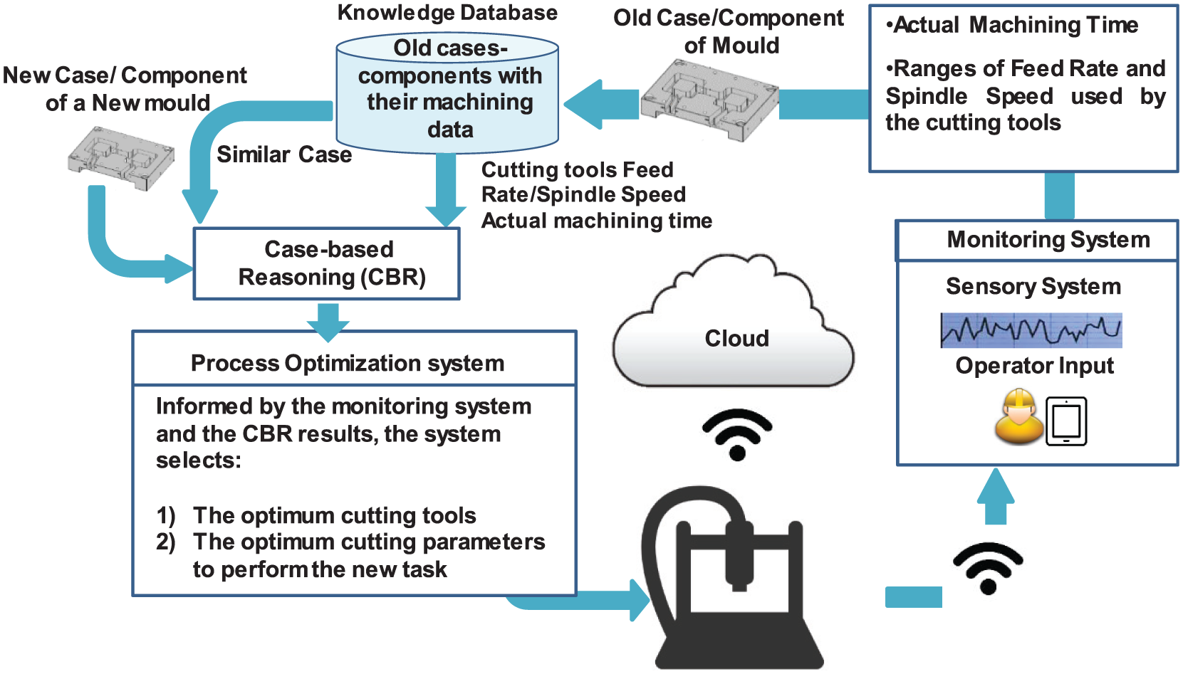
Main architecture of the proposed framework.
Monitoring system
With the purpose to realize real-time shop-floor monitoring, a methodology and a monitoring system have been designed. The proposed system consists of the necessary hardware and software to capture, process, store, and visualize the data retrieved from the shop-floor. The measurements are the outputs of current sensors attached on the main motor drives which are used in a machine tool, that is, the current consumption of the spindle motor and the motors that drive the axes of the machine tool. Furthermore, the angular velocity of the spindle is measured using a Hall-effect speed sensor. The captured sensor measurements are pre-processed in the data acquisition (DAQ) device and are subsequently transferred using wireless communications to a gateway, and then to Cloud. Apart from the automatic sensory measurements, the operator of the machine tool is also integrated in the monitoring workflow by providing information in a semi-automatic manner. The last step of the monitoring system is performed in the Cloud, and includes a decision-level information fusion technique to extract meaningful information from the raw data. The main purpose of the system is the determination of the actual status of the machine tool, along with tool availability and power consumption information. The statuses of the machine that are identified are ‘Available’, ‘Processing’, ‘Down’, and ‘Setup’. The monitoring results feed the optimization system to enable the decision of the appropriate cutting parameters.
Sensory system
The measurement of the current consumption of the main motors is performed as the first step of the monitoring workflow, using a sensory system that is installed in the electrical cabinet of the machine tool. The selection of a sensory system instead of the installation/use of a direct interface with a machine controller is mainly due to the fact that a sensory system is a cost-efficient and easy-to-install solution which is not bound to a specific machine tool. The monitored machine components are the spindle and the motors of the axes, with the current measurements being obtained during the operation of the machine. The selected current sensors are current transformers (CT) packaged as inductive clamps. This selection is encouraged by the non-intrusive manner of inductive clamps and the near-zero power consumption of CT. To support the current measurements of the spindle motor drive with measurements of the mechanical operating characteristics, and to enhance the information that will be provided to the optimization system, a Hall-effect speed sensor is employed.
DAQ
The DAQ device consists of a sensor board and a microcontroller. The outputs of the sensors are connected on the sensor board to prepare the signals for the DAQ device. This hardware preparation is achieved by transforming the current output of the sensor into voltage. The microcontroller pre-processes the data streams by calculating the root mean square (RMS) values for all current measurements. In the occasion of the angular velocity sensor, the digital output is translated into revolutions per minute (RPMs). Subsequently, the data are organized into packets with a specific identification number for each machine for the transmission to the Cloud.
Wireless sensor network
Each DAQ represents a node belonging to a wireless sensor network (WSN) for the machine tools of a shop-floor. The proposed WSN is organized in a star topology with the primary node being a microcomputer acting as a gateway to Cloud, and the replica nodes being the DAQ nodes. The microcomputer coordinates the communications inside the network and transmits the measurement packets received by the DAQs in predefined time intervals of one second. Considering the extended communication range that is necessary on large shop-floors, the radio frequency (RF) communication is selected over Wi-Fi (Figure 2). The wireless protocol used is ZigBee, 47 as it is robust, has low power, provides on-chip encryption mechanism, supports multiple network topologies, and gives the opportunity for thousands of nodes in the same network. Therefore, it is suitable for environments that are harsh in terms of RF communications such as manufacturing enterprises and need secure transmissions to minimize the risks of attacks.
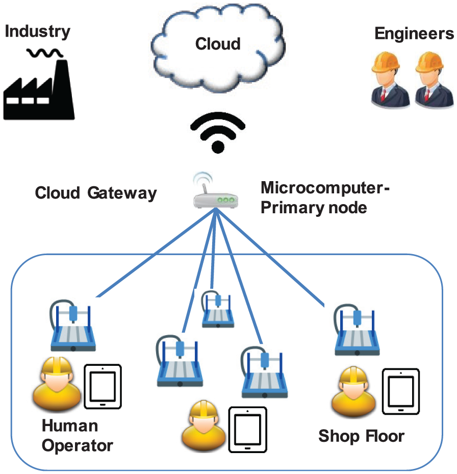
Wireless sensor network.
Input from human operator
The input from the human operator of the machine tool is also considered in the monitoring workflow, for the purpose of providing information on the running task, the cutting parameters, and the tool availability. Specifically, regarding the cutting parameters, the operator informs the system with the range of the feed rate that is used in a task, the spindle speed, and cutting depth. The input from the operator is obtained by using a mobile device which is also used for visualization of results. Furthermore, the operator informs the system with the statuses of ‘Setup’ and ‘Down’ which cannot be identified by the sensory system.
Input from the machine schedule
The schedule of the machine is also included as an input for the monitoring system. The schedule provides information on the current status of the machine and the following tasks. A legacy planning system is integrated in the machine monitoring system, providing it with the machine tools’ schedules.
Information fusion
Taking into consideration the heterogeneous sources which provide the machine status with information, an information fusion mechanism is needed to extract meaningful results. The information fusion is performed at the decision level, pairing the AHP and the DS theory of evidence (Figure 3). For the needs of this work, two levels of information fusion are considered, that is, low-level fusion and high-level fusion which are both applied at the decision level (Figure 4). The low-level fusion is applied for the determination of the status of the machine, considering the sensor output. The sensors are classified in two categories, that is, the sensors that track the status of the spindle and the sensors that track the status of axes. By using ‘If-Then’ rules, the statuses of the table and the spindle are identified independently. In the next step, which finalizes the low-level fusion, the evidence of the spindle and axes monitoring are fused using the DS theory to determine the overall status of the machine tool, based on the sensory system. The high-level fusion is applied to the outputs of the low-level fusion, the status provided by the operator, and the status provided by machine schedule.
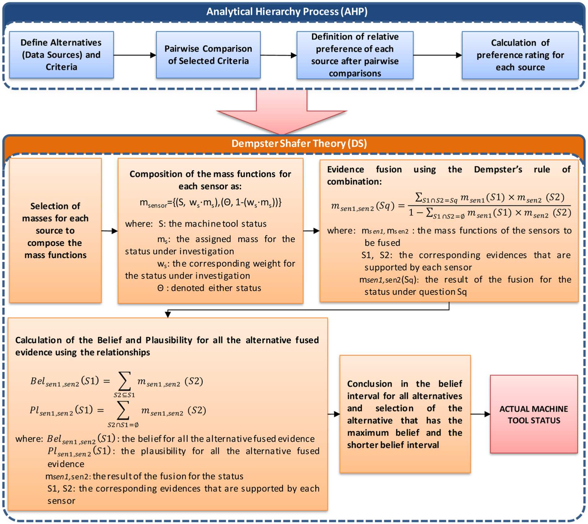
Workflow of the AHP and the DS theory.
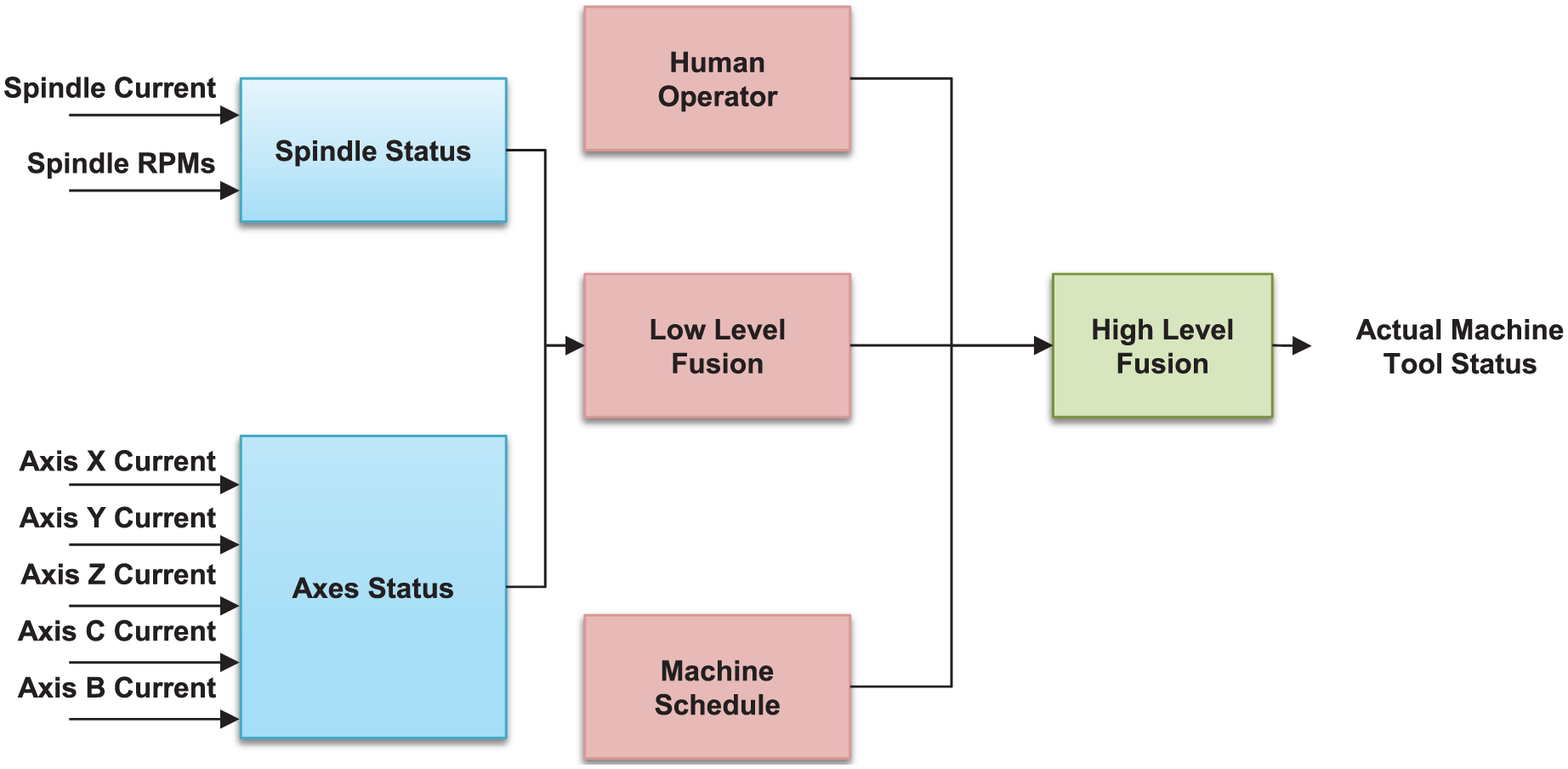
Dataflow of the information fusion.
The DS theory uses a number in the range [0, 1] to indicate belief in a hypothesis, given a piece of evidence. This number is the degree to which the evidence supports the hypothesis. The impact of each distinct piece of evidence is represented by a function called basic probability assignment (BPA) or mass function.
The mass functions for each source of the monitoring system have the following formula (1)

where S is the status (i.e. Available, Busy, Setup, or Down) as indicated by each source, ms is the mass of each source, and Θ denotes either status.
Regarding the low-level fusion, the DS theory of evidence is directly used on the statuses of the spindle and axes. The masses that are assigned to both ‘Available’ and ‘Busy’ statuses for the two sources are 0.5 and 0.9, respectively. This selection has been performed due to the fact that the proposed configuration of the sensor system has high reliability to identify the ‘Busy’ status of the machine tool, but lower reliability to identify the ‘Available’ status as it corresponds only to the availability of the spindle and axes separately.
The high-level fusion includes three heterogeneous sources (i.e. sensory system, operator, and machine schedule) that provide information (Figure 4). For this reason, the AHP is employed to conclude to the relevant weights that will be assigned to the mass functions prior to the application of the DS theory of evidence. This method is among the most employed methods as it provides meaningful information and results. In addition to estimating the relative weights, the AHP method also provides a measure of consistency, called the consistency index. The consistency index provides some pertinent information in terms of how consistent the pairwise comparisons are. Consistency is measured not only in terms of which element between the pair is more important, but also how much more important.
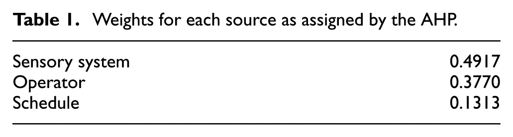
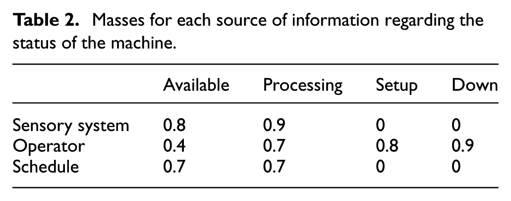
The criteria used in the AHP are precision, synchronization, flexibility, error probability, and prediction capability. Subsequently, pairwise comparisons determine the preference of each alternative over another. Synthesizing all judgments, the weighted average rating for each alternative source is calculated (Table 1). The masses for each source without taking into account the relevant weights are presented in Table 2.
Weights for each source as assigned by the AHP.
Masses for each source of information regarding the status of the machine.
In the next step, the mass functions for the high-level fusion are calculated by formula (2)

where ws is the weight for each source as calculated by AHP.
The results of the information fusion enhance the monitoring data with information on the statuses that cannot be identified by the sensory system and provide more accurate calculations of the actual machining time for each task.
The outcome of the monitoring system is a database containing all information related to the task performed by the machine tool, which is necessary for the efficient operation of the optimization system. This information includes the actual machining time of the task, the energy consumption, the feed rate range and angular velocity, and geometric values of the machined part.
CBR engine and similarity mechanism
Traditional rule-based approaches have been enhanced with CBR systems. 48 The main advantage of the CBR systems is that they can be applied to different problems, considering appropriate adaptations without needing assistance from an expert. CBR is also selected due to its suitability for complex concepts where knowledge is not structured properly. 26 CBR consists of the five main fields: (a) representation and storage, (b) retrieval, (c) reuse, (d) adapt, and (e) retain. Fields (a) and (b) are facilitated by the developed database, while the remaining fields are performed by the optimization system. More specifically, the CBR has seven main steps as shown in Figure 5 below.
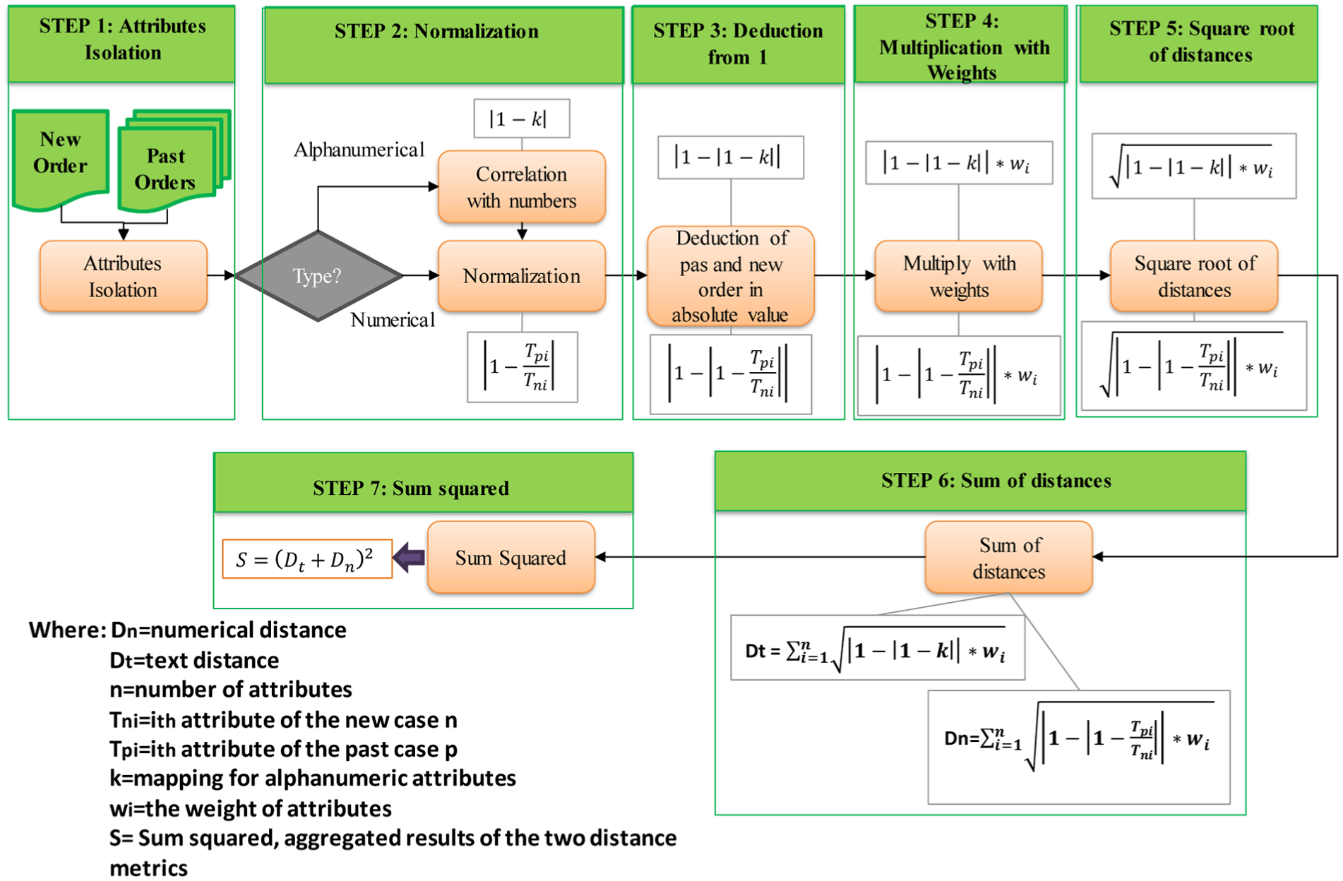
Description of main CBR steps.
The similarity measurement mechanism emphasizes on the differences exhibited between the basic attributes that characterize old and new parts. The past cases, in our work the past tasks, are retrieved from the repository and are compared with the similarity mechanisms. The attributes which are considered from the mechanism have numeric and alphanumeric values. The alphanumeric attributes take discrete values and are matched to numbers between 0 and 1 for normalization reasons. The pairwise comparison is based on the distance between the defined features. Equations (3)–(5) are used to measure the Euclidean distance through a pairwise comparison between the attributes of past and new cases, and specifically equation (5) aggregates the results of the two distance metrics
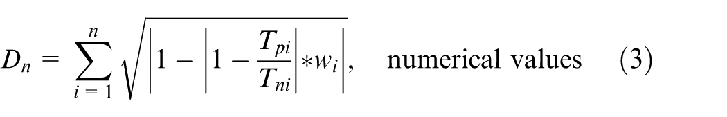
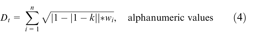

where Dn is the numerical distance, Dt is the text distance, n is the number of attributes, Tni is the ith attribute of the new case n, Tpi is the ith attribute of the past case p, k is the mapping for alphanumeric attributes, and wi is the weight of attributes.
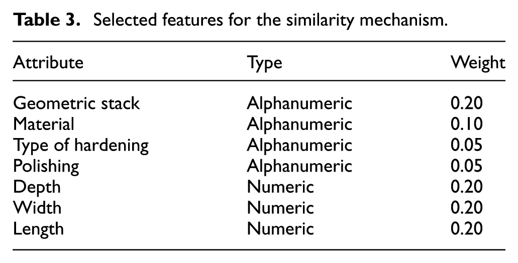
The alphanumeric and the numeric attributes for the similarity mechanism, along with their weighting parameters, are identified by interviewing the designers of a mould-making small and medium enterprise (SME). The selected alphanumeric values are the geometric stack, the material, the type of hardening, and the polishing. The numeric values that influence the machining characteristics are the depth, width, and length. Higher importance was set to the three numerical values by a total weight of 0.6. The four alphanumerical values share a total weight of 0.4, thus they are less important.
The past case with the highest similarity index is analysed first. The user retrieves the data of the most similar case, and based on his or her experience, has the capability to recognize if the described data are adequate to be considered for the new case. In order to further enhance the knowledge retrieval, in cases when the new product requires a different amount of components or processes than the retrieved most similar case, the second similar case can be consulted and afterwards the third one, and so on.
Utilizing the data retrieved from the monitoring system and having decided the matching past similar cases, the machining time and the cutting parameters to perform the new task are confirmed and the final generation of the optimum G-code of the new tasks is settled.
Optimization system
The optimization layer of the system is responsible for selecting the appropriate parameters for machining the cavity. In order for the system to make a well-informed decision, the data from previous cases are taken into account to improve the accuracy and speed of the algorithm. Moreover, the recommendations from the tool manufacturer are also included in the decision-making process. This way, best practice and experience from previous machining can be taken into consideration in the selection of the cutting parameters. The architecture of the system is described in Figure 6.
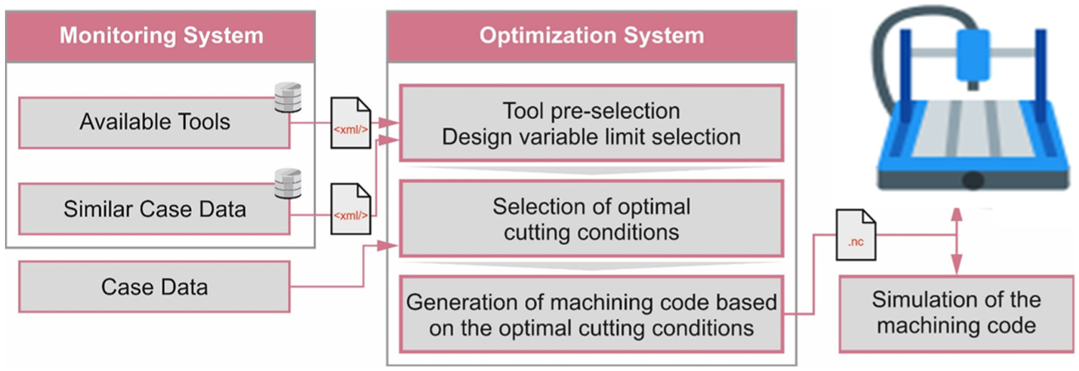
Architecture of the optimization system.
The optimization process starts with the retrieval of the information for the new case, the cases with the greatest similarity to the new case and the tool manufacturer’s recommendations. These data are retrieved through a web interface based on XML. Since the services reside on the same server, there is no need for additional encryption of the data. After the data have been received, the optimization algorithm can be initiated. The optimization is based on a series of mathematical models12,42 which are used to model the cutting process as well as the results in the final part. Knowledge is incorporated in the model by limiting the design space of each variable according to the degree of similarity between the new and the similar case, and the best practices identified from the tool manufacturer. Initially, the module lists all the tools that have been used in previous cases and filters out all the tools that are not able to physically machine the cavity in hand. For the tools that are able to machine the cavity, the cutting parameter range is retrieved. For selecting the range of each cutting parameter in the optimization algorithm, the full range of cutting parameters used in the cases with the greatest similarity is first selected. This range is then compared to the range suggested by the tool manufacturer and the most appropriate range is used for the optimization module.
In the optimization model, the objective function selected was the minimization of the total machining time for the component. This includes the tool replacement time due to tool wear. In more detail, the objective function used in the model includes the machining time (Tm) which is calculated through adding up the time needed for all the movements in the toolpath, and the tool replacement time (Tr) which adds a time penalty proportionate to the tool wear incurred by the specific machining process to the cutting tool. The objective function is summed up in equation 6 49
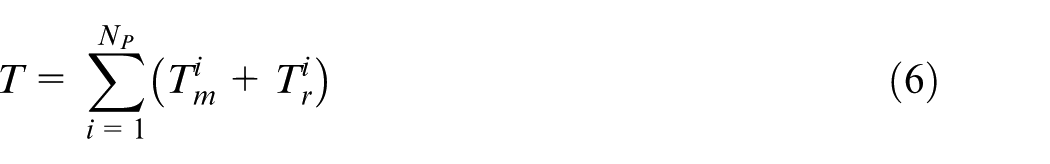
As it can be seen, the total machining time T is the sum of the machining times (Tm) and tool replacement time (Tr) for each depth of cut. These measures are proportionate to the length of the toolpath that is machined in each step (L) and are calculated through the following equations
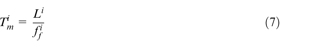
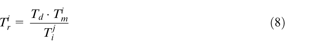
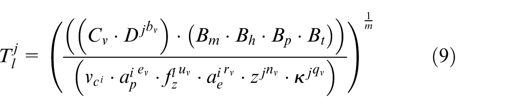
where Bm, Bk, Bp, and Bt are the correction coefficients, Cv is a process constant, κ is the inclination angle, and m, ev, uv, rv, nv, qv, and bv are the exponents.
The constraints used during the optimization process included the machining power, maximum deflection, and surface quality constraint. Since the final geometry has to have some specific quality characteristics, the cutting tool deflection has to be limited so that the tool does not damage the final surface of the part. This is realized in the optimization module by limiting the cutting force to a specific level where the tool deflection is under the permissible limit. This is realized through equations (10)–(12) 49


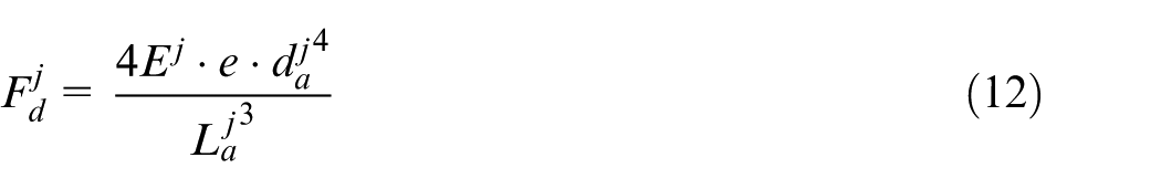
where Cz is a process constant; bz, ez, and uz are the exponents;
In order to prevent the optimization module from selecting cutting conditions that are outside the capabilities of the machine tool, the cutting power constrain is introduced. This constraint is presented in equation (13)
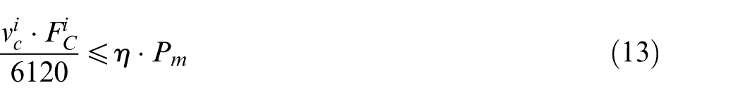
where η is the overall efficiency and Pm is the nominal power of the motor.
Finally, the surface quality of the part has to be in the permissible limits. This is realized using equation (14)
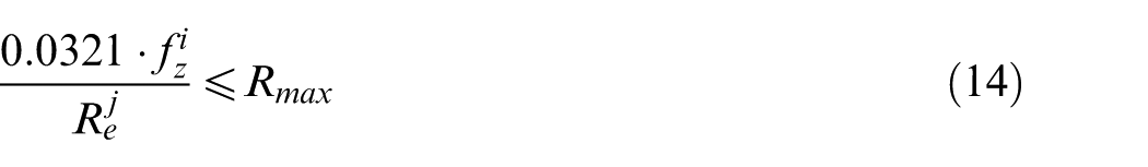
where
After the optimum cutting conditions are calculated, they are used to create the G-code for machining the cavity, which can be sent to a machine tool for machining, and a set of information files are fed to the knowledge repository for use in future cases. The generated toolpath is validated with the use of a simulation software that provides accurate information about the cutting process, the cycle times, and the final workpiece geometry.
Various optimization models have been presented in the literature regarding the selection of cutting parameters; this module aims to create an optimization architecture which takes into consideration the pre-existing knowledge in selecting the optimum cutting parameters in machining. One of the advantages of the proposed approach lies in the fact that it relies on data acquired throughout the CBR module to make a well-informed decision on the cutting parameters that should be used for machining the cavity.
Development of the Cloud-based platform
The proposed framework presents integration between a toolpath optimization system and a machine availability monitoring system, together with a knowledge-reuse mechanism. This integration is enabled by web technologies and specifically Cloud technology. A Cloud infrastructure hosts both optimization and monitoring applications, which are treated as services that can also function in a decoupled way. Both applications are provided to the end-user through the Software-as-a-Service (SaaS) model.
The machine availability monitoring application conforms to the representational state transfer (REST) architectural pattern, which is based on the Hyper Text Transfer Protocol (HTTP). The application is developed in the Cloud using the Ruby on Rails (RoR) framework, an Apache HTTP server, and a MongoDB database (Figure 7).
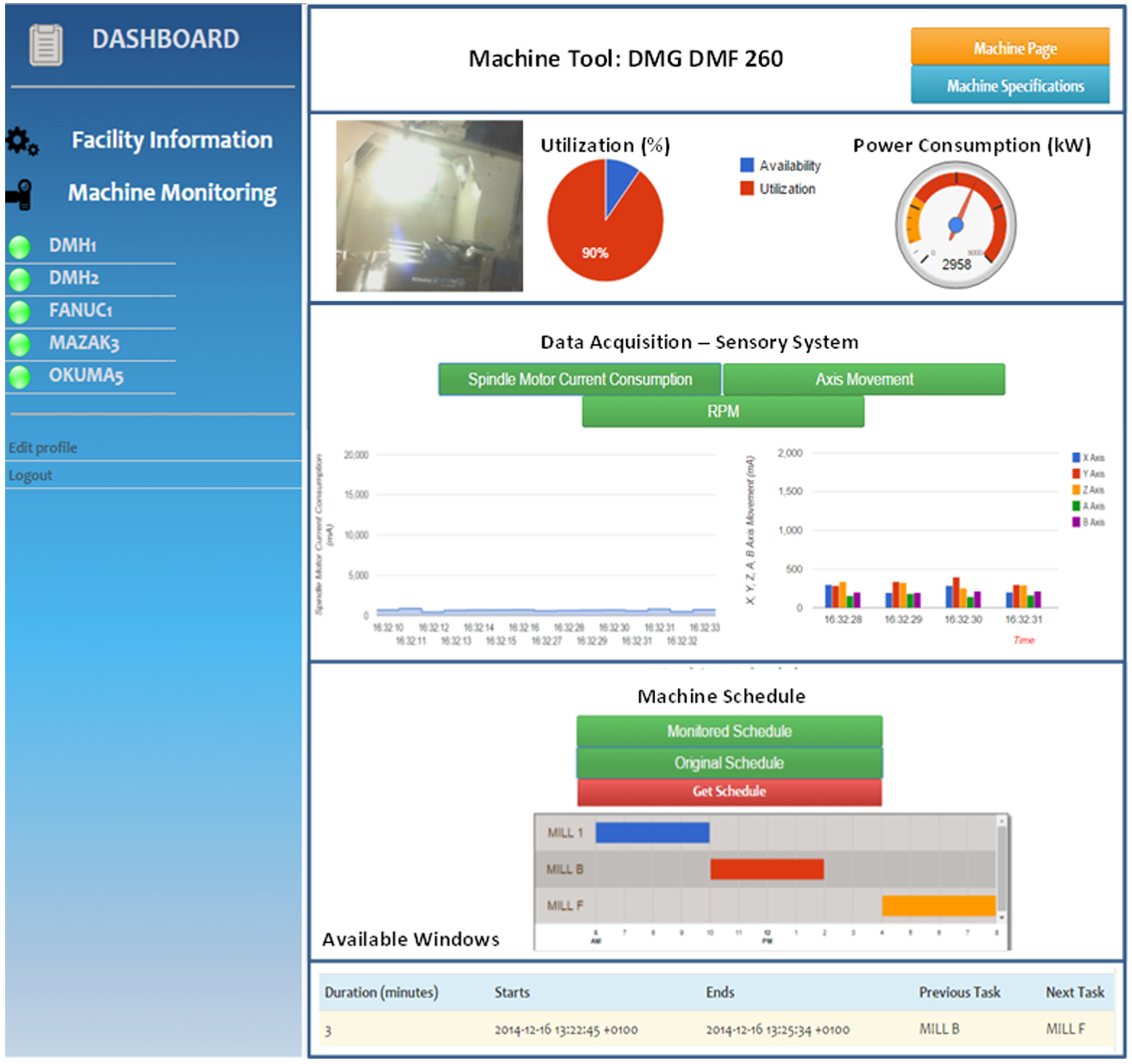
Screenshot of the developed monitoring software.
The optimization module is also hosted in a Cloud environment and is hosted in an Apache Tomcat server. It consumes the data from the availability monitoring module through a well-defined interface and provides the results through XML data and files.
Case study and results
Modern industries around the world are increasingly seeking quick-response and adaptive production systems. The developed platform has been evaluated in the mould-making industry. The case study has been performed in order to demonstrate the benefits derived from the accurate machine tool monitoring, the knowledge reuse through the CBR system, and accurate and optimum cutting parameter selection through the optimization system.
The shop-floor of the mould-making industry is composed of eight job-shops, which include 14 workcenters and 20 machine tools, in total. The machine tools are capable of performing different processes, namely, milling, roughing, turning, drilling, and finishing.
The monitoring system has been setup in eight of these machine tools, for the purpose of monitoring them and capturing the data. More specifically, sensors of the DAQ device have been connected to the electrical cabinet of the machine tools. Moreover, mobile devices have been given to the operators of the machine tools in order to capture the data related to the machine status and the cutting parameters.
In the above-described industry, moulds are considered as manufacturing parts. A mould needs to be designed and constructed in such a way that it can produce an injection plastic component with a single stroke of the press and eject it without any imperfections. Thus, the geometry of every mould component and all the specialized built-in mechanisms, that is, cooling system, are attributes that exponentially increase the machining difficulty, making the manufacturing process extremely time-consuming and exceedingly precision-dependent. Every mould consists of a number of components. The cavity is selected as the new sub-part that needs to be machined. The cavity is a component that characterizes the mould as a part, and the manufacturing of it is deeply related to its geometrical characteristics.
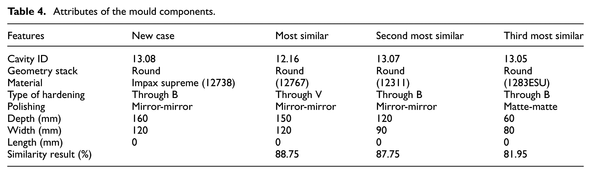
As a result, the attributes that were selected to be utilized through the similarity measurements are the geometry stacks, material, type of hardening, polishing, width, depth, and length, and they have both numerical and alphanumerical values (Table 3). For the purposes of demonstrating the performance of the CBR and similarity mechanism, a comparison of the cases has been performed based on both the numerical and the alphanumerical attributes. These attributes affect the process plan and the cutting parameters’ optimization of the task. The new part in our case is the cavity plate of the 13.08 mould for which we assume that there are no available data related to the cutting parameters and to the real machining time. Based on the CBR methodology, the past parts are retrieved and the similarity mechanism calculates the distance of the attributes using equations (3)–(5), while also considering the weights of each attribute. The similarity measurement has defined the cavity plate of the mould to be 12.16% and 88.75% similar. The ranking of the similarity measurement algorithms identified the cavities of the moulds 13.07 and 13.06 as the next most similar cases, with similarities of 87.75% and 81.95%, respectively (Table 4). Afterwards, the adaption of the data related to the cutting parameters, the cutting tools that were used and the actual machining time is performed.
Selected features for the similarity mechanism.
Attributes of the mould components.
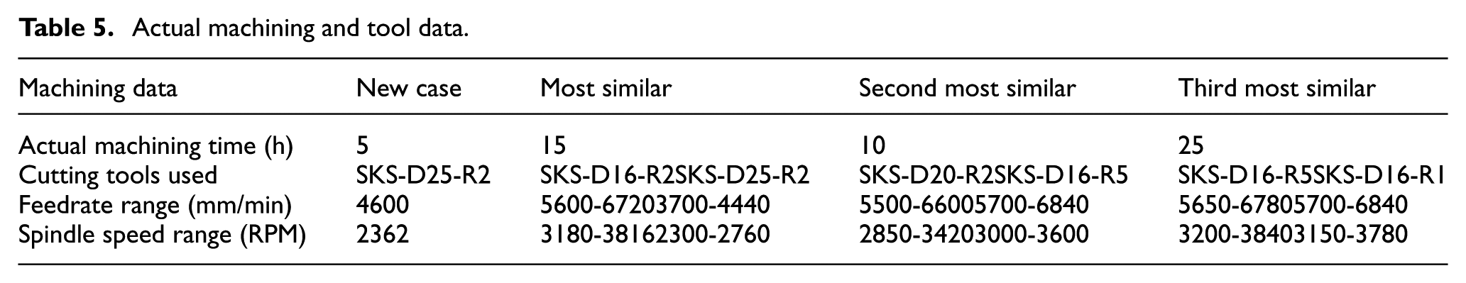
The cutting tools and the cutting parameters, including the feed rate and the spindle speed (Table 5), are obtained by the optimization system. The optimization system uses these data to limit the design space of each decision variable of the optimization model. This way, the design space is reduced and is better targeted to the examined case. After collecting and analysing the data, the optimal cutting parameters are calculated. The optimal cutting parameters are then used to generate the machining code for manufacturing the specific feature. The optimal cutting parameters, as calculated by the optimization module, are presented along with the data provided from the previous cases (Tables 4 and 5).
Actual machining and tool data.
After the end of the optimization, the toolpath generated was used as an input on the simulation software of this module. Figure 8 presents the results of the simulation along with the visualization of the toolpath. As it can be seen, the optimization module was able to calculate a set of parameters which fully use the capabilities of the tools and provide a valid machining code which machines the cavity and is ready to be used in machine tools.
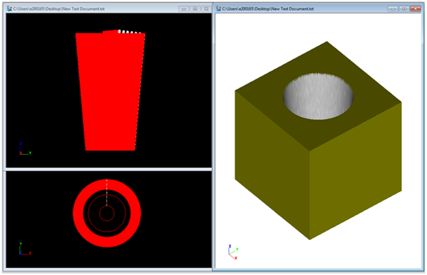
Toolpath simulation for the machining of the new case.
With the use of the proposed approach, the complexity of the decision parameters in modern workshops can be greatly reduced. Figure 9 presents a comparison between the classic approach used in modern workshops and the approach proposed in this research. In the classic approach, end-users have a big number of alternative tools that can be used for machining a specific feature, out of which they have to select the ones that can actually machine the feature in hand.
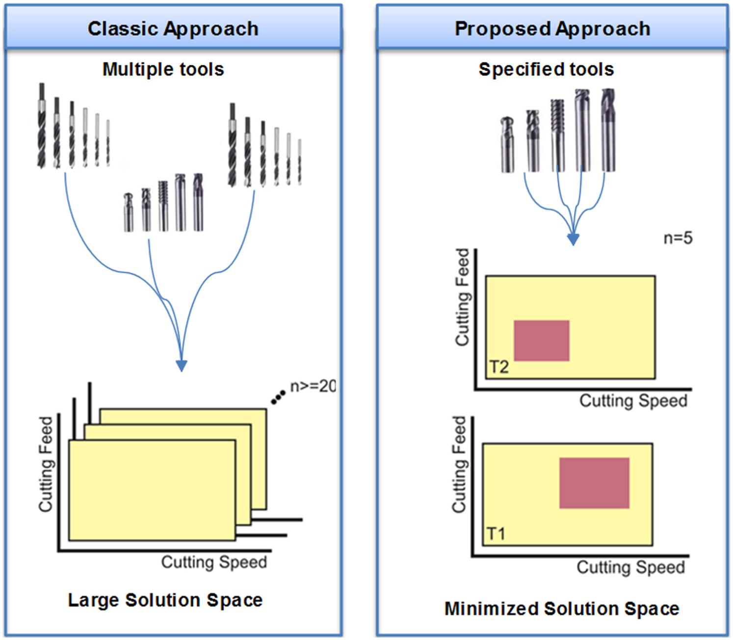
Comparison between classic approach in the selection of cutting parameters and the proposed approach.
After selecting the tools, the cutting parameters have to be selected from the full range proposed by the tool manufacturer (presented in yellow colour, in Figure 9). With the proposed approach, the information from previous cases is used to narrow down the list of available tools to a smaller number that have been used in machining previous similar cases. Moreover, the feeds and speed used in previous cases are also used to dramatically reduce the range of cutting feeds and speeds considered in the optimization process (presented in red colour, in Figure 9). This way the optimization module can deliver the results faster and with better accuracy than by using the traditional approach.
Conclusion and future work
Management of knowledge in modern workshops is one area that could contribute to the optimization of the overall efficiency of production lines to help in achieving a cost-effective and sustainable solution. This article presented a novel framework for managing and reusing existing knowledge from old cases into new components. Knowledge from the workshop is collected through a monitoring system that also incorporates operator feedback. A CBR mechanism is used to select the old cases that are most similar to the new case which is presented to the manufacturer. The knowledge from the past cases is used as an input in an optimization system which calculates the most appropriate cutting parameters for machining the case. After the optimization process, the machining code for manufacturing the part is created and verified with the use of simulation software. By using the presented framework, end-users can benefit from using the knowledge generated by previous cases to reduce the overall production time. Specifically, by performing integrations with real-time monitoring systems, the operations performed in the process planning phase can be enhanced by data derived from the actual shop-floor conditions. Therefore, the awareness on the capabilities of resources can be increased, and non-feasible process plans can be avoided. Moreover, in terms of reducing the iterations with the machine tool while machining new parts, the proposed system can accelerate the procedure by providing in the beginning the near optimum cutting parameters.
As a continuation of the presented work, the authors intend to include energy criteria 50 in the optimization algorithm. The optimization of the power consumption during machining will aim to be facilitated by the power consumption measurements from the monitoring system in order to conclude in a more accurate model. In terms of the monitoring, the authors intend to extend the system by interfacing the machine tool controller to enrich the information gained from the process. Consequently, the operator can be relieved from the duty of providing the used ranges of the cutting parameters after the completion of a machining task. Thus, the procedure will be automated and mistakes relevant to the data collection from the shop-floor can be avoided.
Footnotes
Declaration of conflicting interests
The author(s) declared no potential conflicts of interest with respect to the research, authorship, and/or publication of this article.
Funding
The author(s) disclosed receipt of the following financial support for the research, authorship, and/or publication of this article: The work presented in this paper is supported by the European Union funded research project ‘Collaborative and Adaptive Process Planning for Sustainable Manufacturing Environments – CAPP-4-SMEs’ (Grant Agreement No. 314024).