
Abstract
The superplastic forming process is used in a wide range of high-value-added manufacturing sectors to make lightweight, complex-shaped components for high-performance applications. Currently, it is a high-cost process, for example, the superplastic forming of titanium alloys involves a high-temperature furnace, costly (mould) tooling and has a high utilization of resources such as argon gas and energy. The authors of this article propose a prototype for next-generation superplastic forming laboratory equipment. The aim is to develop improved methods, particularly for heat management in the superplastic forming process, to allow a more widespread application of the process to manufacture lower cost products. The next-generation superplastic forming tool comprises a tool in the form of a hemispherical shell, pressure chamber with incorporated water cooling system and an infrared heating system. The construction, usability and suitability of the next-generation superplastic forming equipment have been proven by a series of physical experiments, and numerical simulations are performed and the results are presented and discussed in this article.
Keywords
Introduction
The aim of the work was to design and construct a prototype for a next-generation superplastic forming (NG-SPF) that utilized novel heat management techniques. This work is part of larger research programme and its contribution to general knowledge is to share with other researchers concept and construction method of NG-SPF. Most significant outcomes of this research are the process through which the setup has been constructed, experimental procedure with use of this setup and possible experimental results.
‘Superplasticity is the ability of a polycrystalline material to exhibit, in a generally isotropic manner, very high tensile elongations prior to failure’. 1 Usually, high temperature and low strain velocity are beneficial for the phenomena to be manifest. Superplastic (SP) materials include some ceramics, metals, intermetallics and composites. There are two common types of SP, fine structure and internal stress. 1 Most materials exhibiting SP behaviour can also be joined by diffusion bonding (DB). 2 In many applications, it is beneficial to SPF material and simultaneously or subsequently DB in the same tool (referred to as SPF/DB). Application of SPF/DB allows production of complex hollow structures with feedstock in the form of metal sheets stacked together that are selectively DB and inflated. 3
SPF has wide applications in a variety of industries, including important applications for aerospace. Among materials used for SPF, most commonly are aerospace aluminium alloys and Ti6Al-4V (Ti6-4). The high value of materials and technologies make components used in the aerospace sector perfect candidates for net-shape or near net-shape forming technologies, for example, aft fuselage of the McDonnell Douglas F-15E Strike Eagle. 4 Production of net-shape or near net-shape is particularly advantageous due to the high machining cost 5 and low machineability 6 of Ti6-4 even when using tungsten carbide (WC)-coated tools. 5
SP can be characterized by a constitutive equation as in equation (1), where

The strain rate sensitivity is proven to play an important role in the thickness variation of the material and increased m will result in more homogeneous thinning of the material. 7
Simulation approach
The Marc & Mentat FEM (Finite Element Method) algorithm is governed by equation (3). Solution of this equation is performed with the use of an iterative Newton–Raphson method. A Multifunctional Sparse Solver was used

The material forming in Marc & Mentat is driven by equation (4), where σ is the stress, A, B, and n are the material parameters, ε is the strain and
The thermal aspect of SPF is very important for this research. Heat is transferred between zones inside one body or between separate bodies only by means of temperature difference. There are three main heat transfer modes, that is, conduction, convection and radiation; all three modes are bound together and in real examples rarely occur separately. Heat transfer is governed by a series of basic laws, the first law of thermodynamics, the second law of thermodynamics, Newton’s laws of motion and the law of conservation of mass and rate equations. SPF and DB tools are exposed to very high temperatures and thermal gradients. The majority of time spent in the process is sacrificed to heating and cooling the tools. 8
Purpose of proposed experiments
The purpose is to perform sheet metal forming where non-contact metal heating is provided with use of infrared (IR) bulbs, where the tool and material temperatures are recorded and final strain of the material is measured. All parameters during SPF are strongly dependent on the process temperature. 7
Increase in fossil fuel prices and the resultant high energy prices have led to increased research on more reliable and energy-efficient production processes. Several authors have indicated the need for the development of more economically effective SPF technologies. Most researchers concentrated on the material rather than the tooling aspect of SPF; therefore, the process remained relatively unchanged since it was introduced to industry. 9
To maintain and hold the process temperature, large amounts of energy have to be used. 10 Classic hot platen setup heat efficiency is between 1% and 5%. 9 Available literature contains some numerical data regarding energy consumption of SPF presses. Representative forming press power consumption is 138.24 kW. Annually, a representative working press consumes 1159 MWh. 11 In 2012, industry paid on average 7.325 pence per kWh, and this equals consumption of approximately £85,000 for one press in 2012. 12 Together with 5% heat efficiency, heat losses account for a loss of £80,000 per annum per representative press.
The time efficiency of the process is increased in approaches proposed by several researchers and inventors. Any possibility of conducting SPF at lower temperatures than used presently in industrial practice decreases cycle length due to possibility of application of shorter heating and cooling times. 13 Classical heating methods have been compared with heating by direct heating methods; initial studies suggested that efficiency of classic processes is 1%–5% and use of direct heating by radiation can result in significant savings. 14
SPF and SPF/DB tooling materials face difficult operating environments due to temperature and thermal cycles, and tool lifetime is directly affected by thermal conditions of the SPF/DB process. 15 Thermal cycles during SPF lead to complicated thermal stress distributions that result in tooling distortion stack-up. High temperatures and stresses during the process cause micro-crack propagation and tool material spallation. Even low thermal gradients in the tooling generate some distortion after application of tool, and workpiece clamping to secure airtightness of the setup also generates high internal stresses. 16
Another effect of growing fuel prices is research on more efficient means of transport. In work describing forming of light elements, it is pointed out that the importance of transport means mass where use of light metal alloys and possibility of forming complex shapes without massive fasteners and joiners offered by SPF/DB are handy. 17 Analytical approach to production of car rim by different methods and their comparison led to conclusion that SPF/DB is good method of production of complex shapes when mechanical fastening and welding are points of possible failure nucleation. 18
An additional limitation is the requirement for isothermal: constant and uniform temperature of the tool and the material. Uniform temperature of material causes uniform plastic properties of the material. The variation of temperature along the material would allow the design of zones of material to undergo more intense deformation and leave relatively undeformed the rest of the material (selective deformation). Uniform temperature of the uniform material determines uniform material flow resistance. 11 The way to introduce non-uniform flow resistance into material of uniform temperature is introduction of structure gradients in the material. 19
Experimental setup design
To mimic the behaviour of metallic sheets during hot metal sheet forming, an experiment using a model material (polymer) sheet was performed. In this experiment, a Perspex sheet with a measurement grid engraved on its surface was deformed against a die made of medium-density fibreboard (MDF). The forming machine used in this experiment was the Formech FM660 in which the forming pressure was applied by the means of a suction pump and heat provided with the use of IR emitters. The sheet temperature was elevated to the forming temperature of the material, and forming was performed. After deformation, the dimensions of the grid elements between the equator and spindle of the product were measured, and the deformation percent strains of the workpiece were calculated as described by the British Standard Organization. 20
To estimate the efficiency of the IR emitters used in the construction of the experimental setup, heating trials were performed. The 500-W IR emitter was placed at a distance of 100 mm from the Aluminium foil. The sheet temperature was measured before the experiment and after the temperature stabilized.
Experimental procedure
The forming temperature for the polymer sheet is 120 °C. Polymer sheet thickness is 2 mm. Polymer sheet surface is not altered with use of any materials used for change of emissivity coefficient of the sheet surface. The polymer experiment is ultimate test of the experimental setup and provides data to compare material behaviour for future physical modelling of the Ti6-4 with use of polymers.
The metal sheet is clamped between the upper case and lower case. After sealing the chamber, argon gas is introduced and the IR emitters turned on. The emitters are used to directly heat material until its temperature reaches SPF temperature. After the material reaches the desired temperature, argon is introduced to the upper chamber to deform the workpiece against the lower chamber.
In case of uniform sheet surface absorptivity, it is expected that the sheet temperature will be close to uniform along the line between the centre of the sheet and the periphery of the active sheet zone.
Five metal forming experiments were performed. The absorptivity of the metal surface is varied by painting it. Initial experiment is performed with surface of the material not altered, and for remaining experiments, the surface of the feedstock is painted before the experiment. In second experiment, surface of the material is painted black for maximum possible absorptivity; in the third experiment, active surface of the material is painted white for minimum possible absorptivity. The fourth and the fifth sample active zones are painted in non-uniform way so the 30-mm-diameter circle in the spindle of the sample is highly absorptive and periphery is highly reflective for the fourth sample, while absorptivity distribution for the fifth sample is opposite.
Set of thermocouples placed in the tool and the material is used to measure temperature. The thermocouple readings are collected and analysed in real time. Results of real-time sheet temperature analysis are used to control power of IR emitters and consequently heating intensity. The thermocouple measurement results gathered by the PC are analysed and compared with results of numerical simulations performed in initial stage of the research regarding thermal effect of uniform sheet emissivity coefficient variation 21 and effect of controlling non-uniform material emissivity coefficients on the thinning of the material 22 during hot sheet forming. After the deformation, strains of the workpiece are calculated as described by the British Standard Organization. 23
Preliminary experiment results
Polymer blowforming
Polymer sheet was blowformed against MDF die. 21 Before deformation, thickness of polymer sheet was measured. After the deformation of the sheet, the dimensions of the measurement grid were measured and material thinning was calculated. The results of polymer hemisphere thickness measurements are presented in Figure 1. The best fit–trend line equation is Relative_material_thinning (x = Angle (0 = periphery)) = 4e*10−5x2 + 0.0062x + 0.4539, R2 = 0.601.
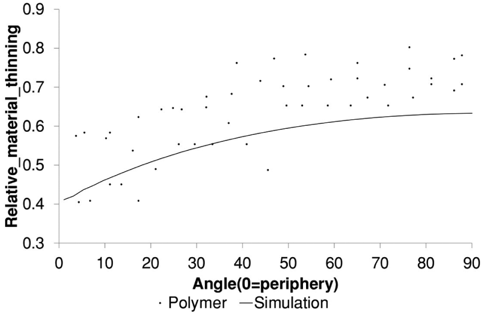
Material thickness measurements in polymer experiment.
Radiation measurements – temperature of the aluminium sheet heated up by 500 W radiator
The heat transfer between the radiation and metal sheet was investigated. Aluminium foil was placed vertically parallel to IR emitter, and the distance between emitter and the foil was 100 mm. The initial temperature of the metal sheet and the environment is 18.3 °C. Steady state sheet temperature is 57.5 °C. The reflectivity of aluminium foil is 0.88. Convective heat transfer coefficient between the foil and the environment is estimated to be 5.98 W/(m2 K), what in this condition gives heat flux of 234.4 W/m2. Radiation heat flux to the environment is 32.3 W/m2. Total heat flux from the foil to the environment is 266.7 W/m2. Total heat loss of the foil to the environment is 5.33 W, what is balanced by the radiation transfer from the IR emitter. Typical short-wave IR emitter tungsten filament temperature is 2200 °C. Heat exchange by radiation and energy balance equations allowed calculation of bulb emissivity coefficient to be 0.12.
Numerical simulation results
Axisymmetric model was prepared. 22 The purpose of this simulation is to estimate possible behaviour of the material during the experiment. A model consists of two contact bodies: a flat sheet at the left and a die at the right. The deformable material is clamped on its periphery, and once it touches the tool, the contact interface is stable. Constant pressure is applied to the metal sheet so that it is deformed against a hemispherical tool with fillet to create a hemispherical shell. Conclusions from cited work are as follows: cold tooling can be used for SPF, at high temperatures, with the suitable choice of low emissivity coatings and heating of the other side of the sheet. Cold tooling does not heat up substantially despite the long forming times (as compared with hot stamping in cold tools) and elevated temperature required for SPF. 22
Axisymmetric model was prepared. A model consists of three bodies: a radiator on top, a flat sheet in the middle and the die at the bottom. The deformable material is clamped at its periphery, and once it touches the tool, the contact is stable. Constant pressure is applied to the metal sheet so that it is deformed against a hemispherical die. The updated Lagrangian formulation was used. The simulation involves nonlinear large deformation. It consists of complicated thermomechanical relationships including heat transfer by radiation and thermal sensitivity of the material. The material strain rate is governed by equation (4) where parameters are strain rate and temperature dependent, and their values have been set to reflect behaviour of material fabricated with use of ALM technology. 24 Cavity radiation viewfactors are recalculated with every 10th time step. Material is thermally and structurally isotropic. FEM mesh is presented in Figure 2.
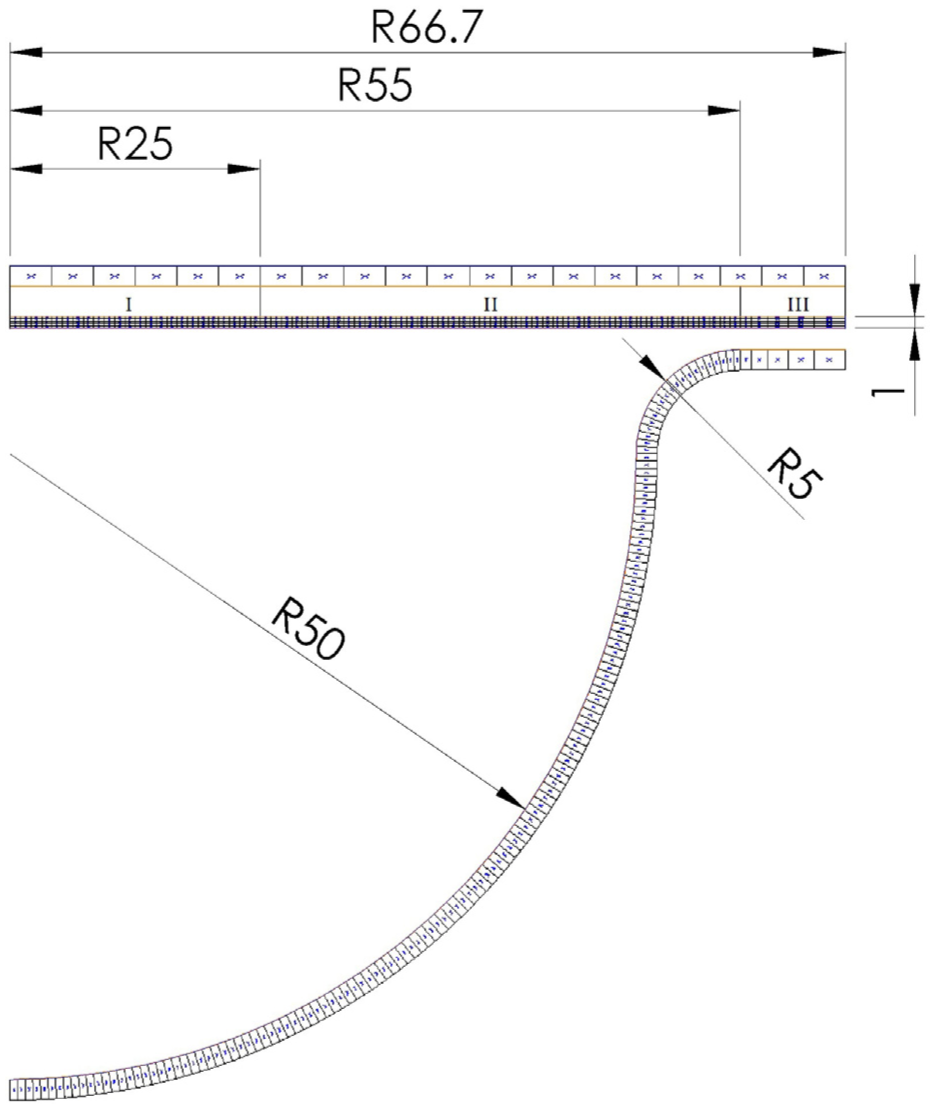
FEM mesh of the model with indicated emissivity coefficient zones in numerical simulation.
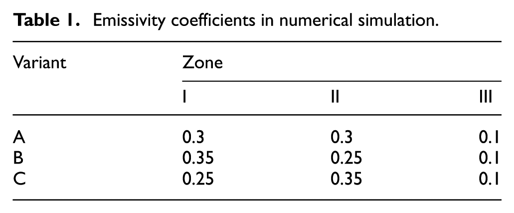
The following simulation parameters were used: die and heater temperatures were set at constant level of 1000 and 100 °C, respectively, and initial material temperature was 100 °C. The heater emissivity coefficient was set to 1, and the tool and the material surface facing the tool emissivity coefficients were set at 0.2. Emissivity coefficients of the sheet surface facing the heater are summarized in Table 1.
Emissivity coefficients in numerical simulation.
The simulation consists of two loadcases. In the first loadcase, radiation is turned on for 600 s to allow temperature of the sheet to stabilize; during this loadcase, only minimum pressure of 10 Pa is applied to initiate approach of the sheet to the tool without inducing stresses initiating deformation of the sheet. The second loadcase adds pressure of 1 × 10⁶ Pa across the sheet as a forming pressure, and the pressure is constant for 10,000 s.
Material thinning was calculated at the end of each simulation. For each simulation, temperature distribution was measured after initial 600 s of the simulation. The temperature distribution was read as an average at each cross section of the material.
Figure 3 presents the thinning results of this simulation. In this figure, it is seen that the difference in emissivity coefficient of the surface has a significant effect on the thinning distribution that has distinguished middle sheet sections corresponding to a higher emissivity coefficient zone in the case of B and a lower emissivity coefficient in the case of C.
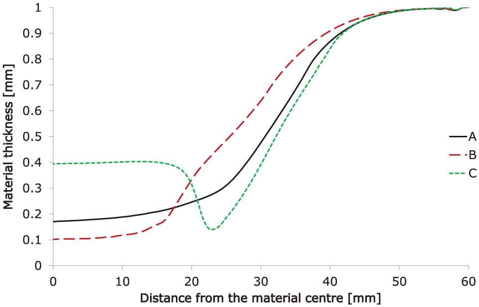
Effect of the heating variations on the material thinning in numerical simulation.
Figure 4 presents the temperature curves after 600 s. After 600 s, the temperature levels are set and differences between cases and heating zones are noticeable. The temperature graphs meet at transition zones between the low emissivity coefficient and high emissivity coefficient zones in the material (between I and II). This is because hotter material is more easily deformed and exhibits higher thinning. The thinning difference is corresponding with temperature difference.
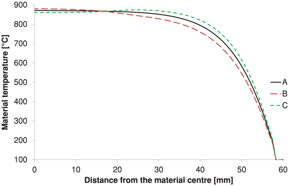
Effect of the heating variations on the material temperature distribution after the first loadcase.
Conclusions from these simulations are as follow: the distribution of the material thinning can be altered by selective heating and cooling of the material. The effect of the changes is affected by material parameters such as its physical properties and by its shape. It is possible to control the deformation parameters and the thermal phenomena by the changes of the material shape and by the changes of the material properties. The strain rate, and its distribution, during the forming process can be altered by appropriate application of applied heat. Even so low change of emissivity coefficient as 0.05 significantly alters thinning of the material.
Proposed NG-SPF setup and experimental procedure
The goal of the design is to closely simulate and perform the industrial SP blowforming process and, at the same time, keep the experimental process simple and easy to operate. To carry out an SP blowforming process, there are many important parameters to be considered, including operational parameters such as pressure, forming temperature, the mechanical and thermal properties of the SP material, the thermal properties of the material surfaces, geometrical properties of the forming dies, the temperature of die surrounding and heat transfer from the die. These parameters form a range of requirements which must be met by the experimental device in order to perform a representative experiment. The main requirements of the experimental device design are as follows: controllable forming pressure, controllable forming temperature, controllable emissivity coefficients of material and tool surface, controllable tool insulation properties, removability of the sheet and the dies after experiment completion, measurement of strain, measurement of tool and material temperature in several points and operation under combined process parameters.
The experimental setup is presented in Figure 5. The window clamp and upper case are equipped with water cooling channels. The inner diameter of the tool is 100 mm. The diameter of upper case insulation hole is 120 mm to create active part of sheet corresponding with diameter of the forming tool. Tool is equipped with series of channels where three couples of thermocouples are placed. On the bottom surface of the workpiece, three thermocouples are placed at points corresponding to the placement of the thermocouples in the tool. The thermocouples in the tool and the workpiece are placed in the spindle of the tool, its periphery and mid-arc of the tool. The chamber between the tool and the lower case is filled with insulation material.
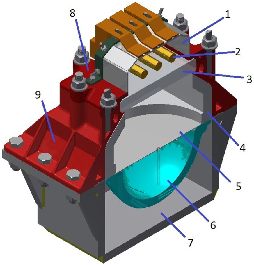
Proposed prototype project. 1 – mirror, 2 – IR emitter, 3 – quartz window, 4 – upper case insulation, 5 – workpiece, 6 – tool, 7 – lower case, 8 – window clamp and 9 – upper case.
The temperature is increased by means of IR bulbs and decreased using water or air cooling. To control temperature of the workpiece, a set of thermocouples and a digital controller are used. The pressure during the forming is maintained at constant level by use of standard BOC pressure controller to increase pressure and solenoid valve to release portions of gas in case the pressure is too high. The pressure is continuously measured with use of pressure transmitter. All temperature and pressure data are collected and logged with the use of PC. Several elements of the experimental setup are made with use of ALM technology; window clamp and upper case are made of maraging steel 25 and the tool is made of Co-Cr steel. 26
Simple schematic of data acquisition and control system is presented in Figure 6.
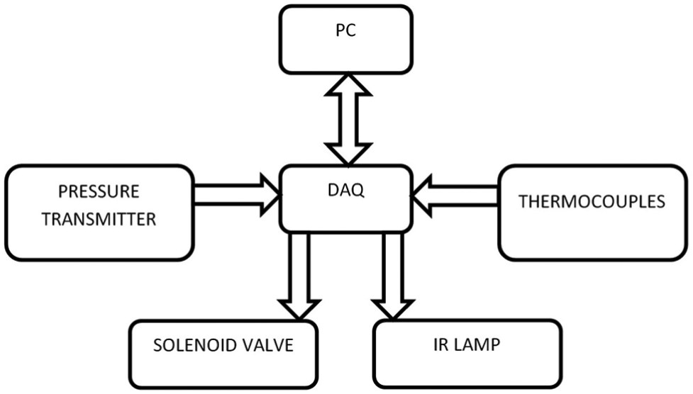
Data acquisition and control system schematics.
The experimental setup incorporates eight K-type thermocouples and pressure transmitter as a means of data collection. Placement of the thermocouples is indicated with circles in Figure 7. The temperatures and the pressures gathered in real time are analysed with use of IBM PC computer with National Instruments NI USB-6229 as a communication interface. The temperature and pressure are analysed in real time, and analysed information is used as feedback information. The temperature curve from thermocouple placed in the centre of the feedstock is used to control power of the IR emitters in order to maintain temperature at constant level. The inert gas is introduced to the system by means of standard BOC pressure controller, and the pressure on the valve is set up to nominal forming pressure. The pressure curve is used to control opening of the solenoid valve releasing gradually excess pressure. Solenoid valve opens when pressure in the chamber is 105% of nominal pressure and shuts when pressure in the chamber equals nominal forming pressure. Additionally, the pressure release valve has been installed in case of emergency pressure release need.
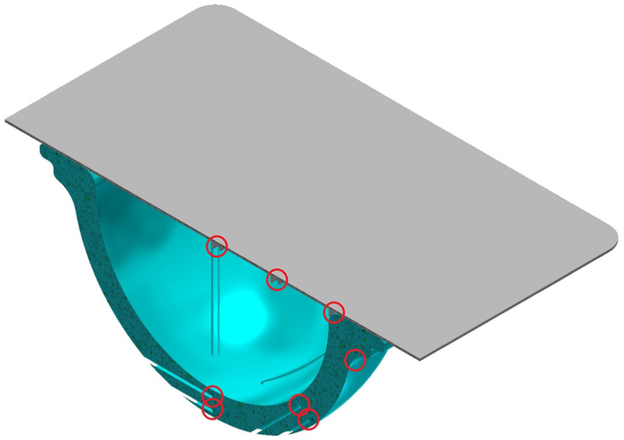
Thermocouple placement in the proposed prototype.
The experiment with use of metal sheet will be performed by blowforming of a material sheet clamped between the top and the bottom casing. Before the experiment, the tool surface is covered with yttrium oxide powder as high reflectivity and stop-off material. After the chamber is sealed, the material temperature is elevated to the forming temperature. Direct heating of material is performed using the IR lamp. When the material reaches forming temperature, the argon is introduced to maintain constant forming pressure of 10 atm.
The bottom side of the workpiece was marked with a measurement grid analogous to the one on the polymer sheet, and the measurement grid was placed in the middle of the workpiece in a rectangular grid of 109.25 mm × 109.25 mm. The details of the measurement grid are presented in Figure 8, and the height of feature printed on the bottom surface of the workpiece is 0.2 mm. Additionally, three couples of thin plates were placed on the bottom side of the workpiece to hold the three thermocouples in the desired positions. The thermocouple holders are located in the centre of the sheet, 25 mm from the centre of the sheet and 50 mm from the centre of the sheet.
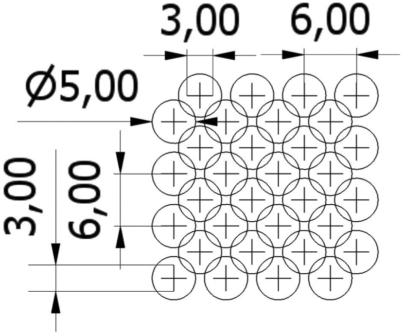
Fragment of the measurement grid.
Experimental setup–related numerical simulations
A numerical model of the quartz window was prepared. The purpose of this simulation is to estimate maximum working pressure of the quartz window used in construction of the proposed setup. In this simulation, the MSC Software Marc & Mentat® multi-physics simulation software was used. The model consisted of one body: an elastic body is clamped to a stiff frame and uniform pressure is applied across the free surface of the body to simulate the quartz window clamped between upper window clamp and the upper case visible in Figure 5. The model consists of 1323 full integration solid elements. The multifunctional sparse solver was used to solve the equations. Young’s modulus of the material was E = 71.7 GPa, and Poisson’s ratio ν = 0.17. 27 The dimensions of the plate are 105 mm × 105 mm × 15 mm. The pressure used in this simulation increased gradually from 0 to 50 MPa applied on the surface of 95 mm × 95 mm in the middle of the plate, remaining edges and surfaces are clamped. During the simulation, the maximum compressive and tensile stresses were recorded. The model and the load distribution are presented in Figure 9.
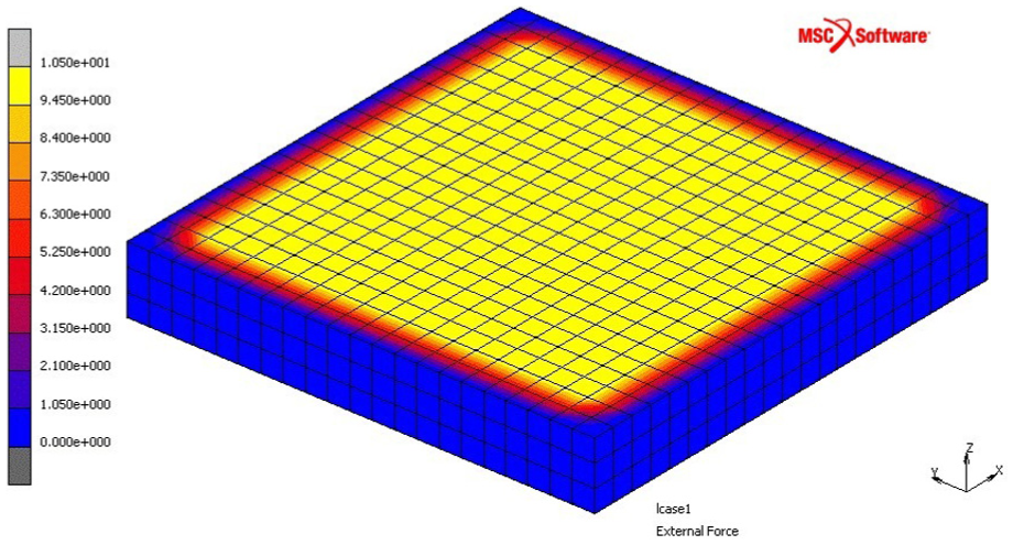
Quartz crystal model with load distribution.
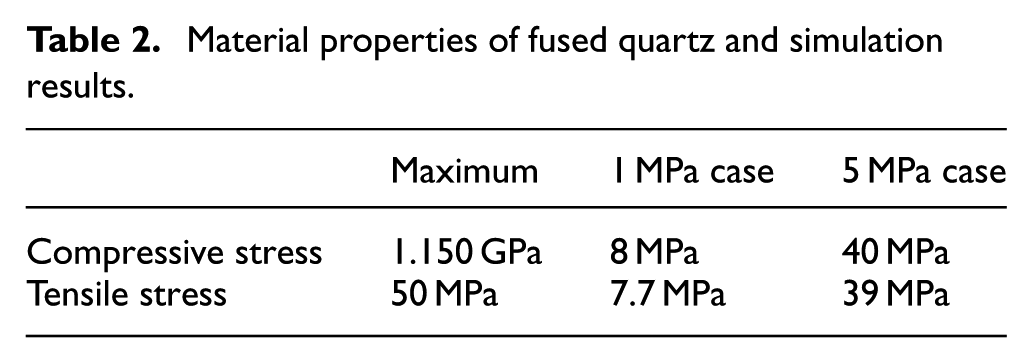
The results of the simulations and compressive tensile material parameters are presented in Table 2. In the second column of Table 2, parameters of the material are listed; in the third column, simulation results for applied pressure of 1 MPa are presented; in the fourth column, simulation results for applied pressure of 5 MPa are presented.
Material properties of fused quartz and simulation results.
A seal is made using high temperature resistant silicone glue between the quartz crystal and the metallic clamps. The glue works as a cushioning material due to thermal contraction and expansion of the setup elements. The other role of the glue is to secure an airtight seal between the window and the metallic elements of the casing.
The static numerical model of the window clamp was prepared. The purpose of this simulation is to estimate maximum temperature to be reached by the window clamp. A coupled thermomechanical computational fluid dynamics (CFD) simulation was prepared with the use of CD-Adapco STAR-CCM+ 9.06. The model consisted of two bodies – solid clamp and coolant fluid. The solid domain consisted of 958,927 elements. The window clamp material was compliant with EOS M300 maraging steel. 25 The fluid domain consisted of 91,034 elements. The fluid initial temperature was 21 °C for air and 3 °C for water. Fluid mass flow was 0.043 and 0.00136 kg/s for water and air, respectively. The heating of the system occurred by the exposure of the frame of the rectangular central opening of the steel clamp, and the cooling of the system occurred by heat exchange to the fluid and the remaining walls of the setup were adiabatic.
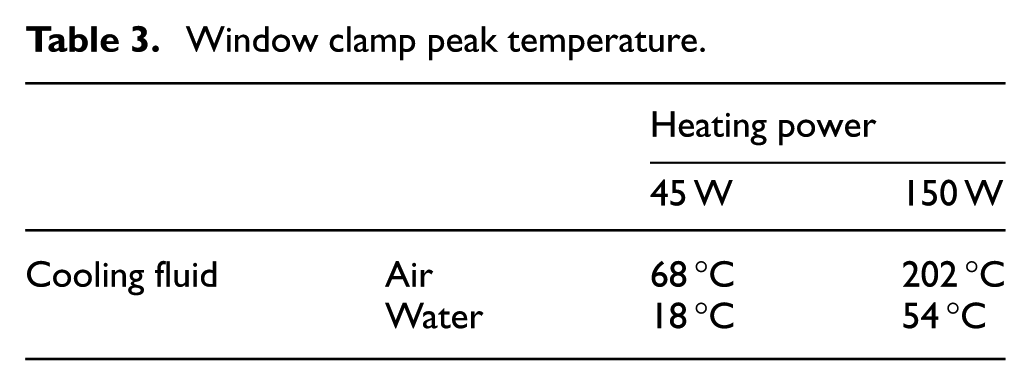
The temperature distribution in the coolant and the window clamp for case with air cooling and 150 W heating used is presented in Figure 10. The results of thermomechanical CFD simulation are presented in Table 3. The maximum temperature of clamp material in this simulation was 202 °C. The maximum operating temperature of maraging steel is 400 °C.
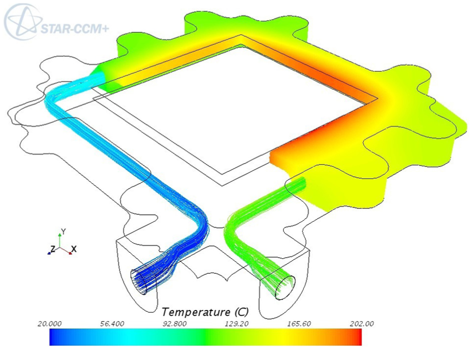
Temperature distribution in the coolant and the window clamp.
Window clamp peak temperature.
Numerical model of setup was prepared. The purpose of this simulation is to estimate maximum working temperatures of the proposed setup. A model consists of a number rigid bodies, as shown in Figure 11. The model consists of 1296 full integration planar solid elements. Multifunctional sparse solver was used to perform the calculations. In this simulation, the MSC Software Marc & Mentat multi-physics simulation software was used. Whole setup initial temperature is 23 °C, and heater temperature ramps from 23 °C to 2200 °C in first second to remain constant during rest of the simulation. The cooling liquid temperature is 23 °C, and heat transfer coefficient is 100 W/m2 K. The air cooling of the setup is applied by application of surface film on the outer surface of the casing, and the air temperature is 23 °C and heat transfer coefficient is 30 W/m2 K. Tool, 26 casing, 25 sheet 28 and insulation material 29 properties are applied as in available datasheets. The model incorporates upper radiation cavity between radiator, insulation, material and casing, and lower radiation cavity between material and tool.
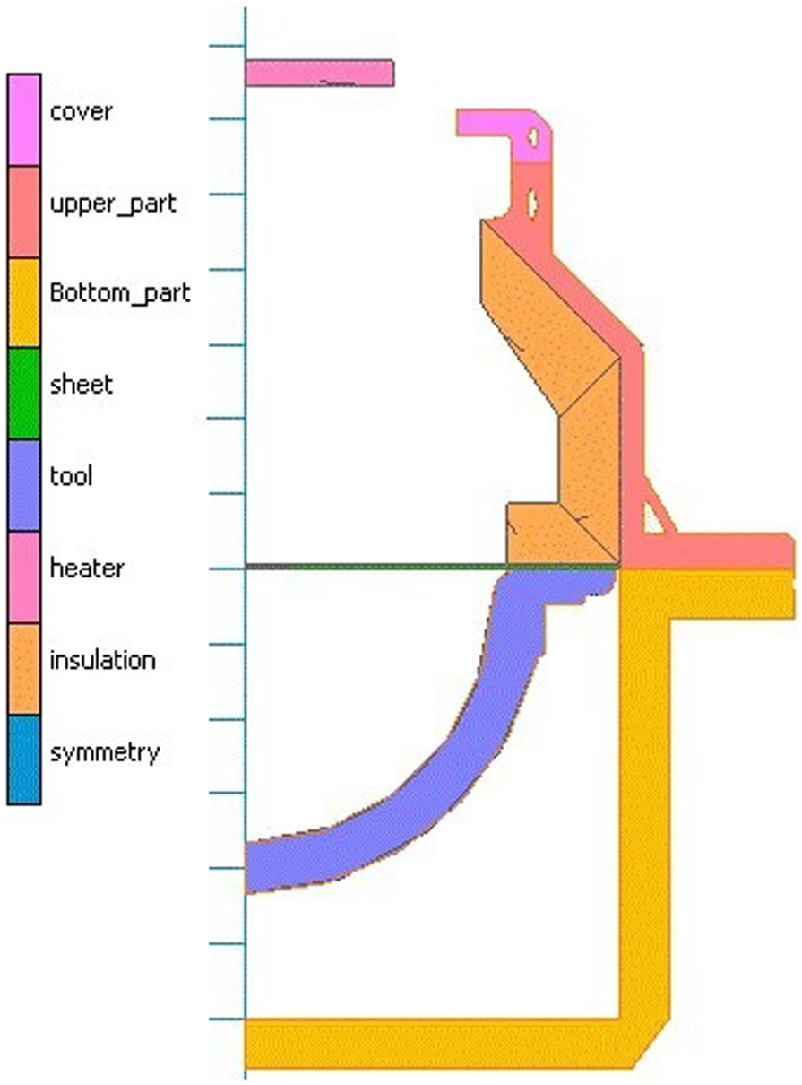
Contact bodies in setup simulation.
It can be observed in Figure 12 that most of the material reached the forming temperature after 53.5 s. When the material reached the forming temperature, the rest of the experimental setup did not reach temperatures that would damage the tool elements. The cooling system is able to remove and manage heat in an efficient way and the insulation of the pressure chamber performed well and did not allow overheating of the chamber walls.
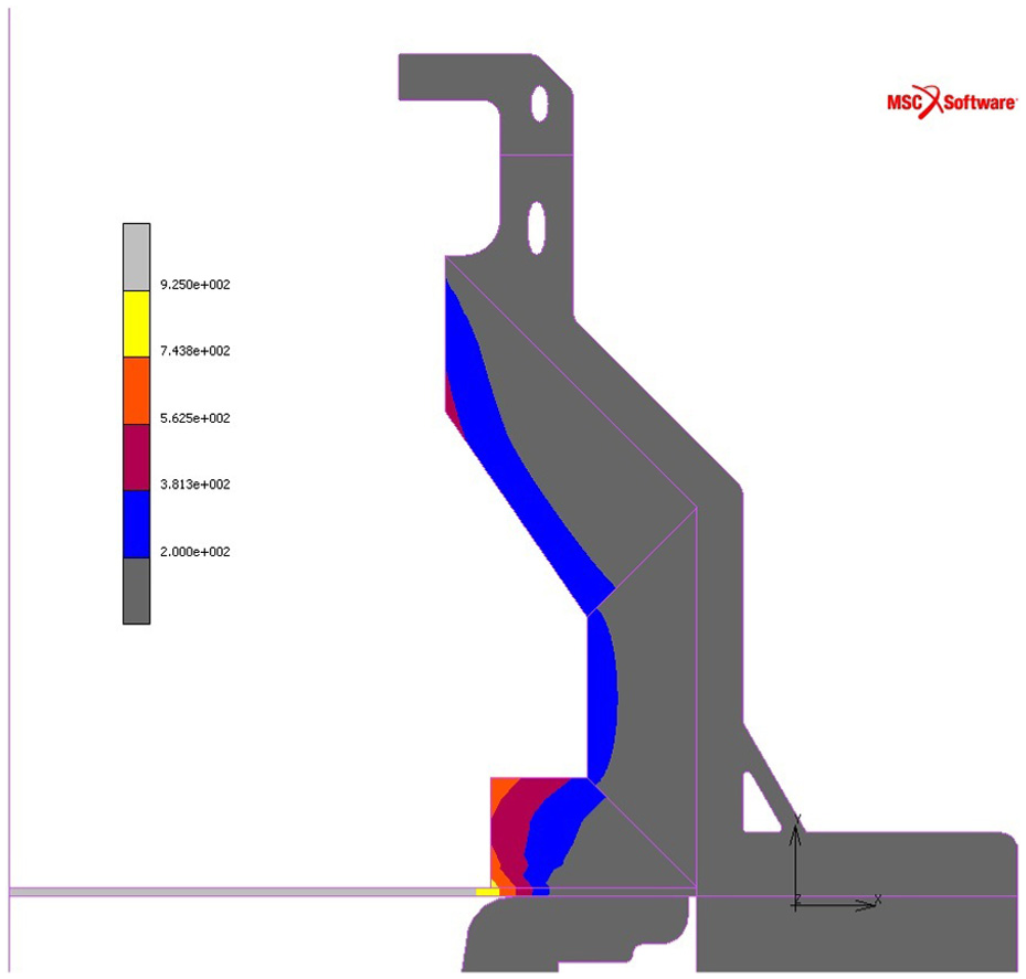
Temperature distribution in the setup elements when material reached forming temperature. Temperature in Celsius degrees.
Discussion
For the experiments performed to date, a hemispherical shape of tool was selected due to its simplicity and historic usage for forming limit type experiments. To measure strain present during metal forming, a measurement grid is engraved on the surface of the workpiece.
To measure temperatures of tool and material, thermocouples placed in three zones are used. Thermocouple placement is visible in Figure 7. Such placement of thermocouples provides information about the most extreme conditions present in the experiment and one intermediate reading. Each thermocouple in the material measures temperature in real time. In each of the two points in the tool are placed two thermocouples, 1 and 3 mm below the surface of the tool to create heat flux meters, in the third point thermocouple is placed on the external surface of the tool.
The tools used are made with the use of direct metal laser sintering (DMLS) using an EOS Eosint 280 machine. 30 DMLS is chosen as a technique to manufacture important elements of the setup as this technique allows the designer to be unconstrained by limitations of traditional production methods. The most important characteristics of the elements built with use of DMLS technique are high shape accuracy and ease of incorporating conformal cooling channels in the product itself. 31
The tool is the most important part of the chamber and subject to very high temperatures and steep thermal gradients. EOS CobaltChrome MP1 steel is selected as a tool material. And it has a maximum operating temperature of 1150 °C. 26
Other crucial elements of the chamber are the window clamp and upper case both being parts of the pressure chamber assembly. Both elements are made of MS1 maraging steel with maximum operating temperature 400 °C. The minimum shell thickness of 5 mm was selected as providing good thermal conductivity and sufficient mechanical strength to withstand 10 atm pressure in the chamber with a good safety margin.
The thickness of the quartz window was designed to be 15 mm using the empirical equation and application of a safety factor 8.
For this experiment, Ti6-4 sheet metal fabricated with the use of EOS Eosint 280 machine is selected as a workpiece. This work relates mostly to Ti6-4 SPF as this is one of most commonly SPF-formed material. Ti6-4 has a low thermal conductivity when compared with other metallic materials; therefore, the distribution of the temperature across the material will not be achieved as quickly as in the case of other materials; differences in material behaviour originating in temperature difference will be more pronounced. Ti6-4 thermal conductivity is 7 W/m K, maraging steel thermal conductivity is 22.5 W/m K and copper thermal conductivity is over 350 W/m K. Another advantage of the Ti6-4 is its readiness to be produced with use of DMLS or selective laser melting (SLM) techniques. Ti6-4 elements produced with DMLS and selective laser sintering (SLS) techniques exhibit a microstructure and macrostructure promoting SP behaviour and such phenomena were observed in as-produced elements without any additional post-processing. Additional advantages of the rapid manufacturing processes such as ease of one-off manufacturing, ease of design modification in case of needs and unconstrained shape design freedom are also beneficial for this research. 32
Design of the experimental setup and procedure also allow replacement of Ti6-4 sheet with St316 stainless steel sheet fabricated with use of Renishaw AM250. 33 Deformation characteristics of St316 were studied in the temperature range of 850 °C–1050 °C, and strain rates used varied in range of 1 × 10⁻⁴–1 × 10⁻¹ s−1. It was found that the flow stress was strongly dependent on the temperature and strain rate. 34
Simulations presented in this work carry several assumptions. The most important are property parameters of the materials used in the simulations. The deformed material is defined by Power Law Model. The mechanical parameters of the material are temperature and strain rate dependent. The most uncertain material property used in the simulations is the emissivity coefficients of the surfaces of materials, which in most cases were estimated from information in available literature. The emissivity coefficients in simulations are always temperature and light wavelength independent.
Further assumptions in the modelling are associated with the thermal boundary conditions used. In the experimental setup, heat evacuation to the environment was necessary and this influenced the overall thermal balance. In simulations, where local variations of material surface temperature were applied, the setup does not exchange temperature with the environment. In all simulations, the heating elements are assumed to be at a constant uniform temperature during the forming stage. Finally, in CFD simulations, the initial temperature of coolant was assumed to be constant.
The greatest limitation of the experimental forming setup is its size and this limits the sample size, power of the heating elements and maximum forming pressure; it also necessitated a cooling system. However, knowledge and experience gained during construction and use of this experimental setup can be used to build a full-scale industrial SPF press with higher energy efficiency.
In the experimental setup, the maximum power of the heating elements is limited by the size of the window through which the material is irradiated and the largest feasible elements have a maximum power of 500 W; the summative power of the heating elements is 1500 W. The experimental setup was designed to SPF Ti6-4 but due to the heating power limitations which causes risk of too slow material heating or not reaching temperature sufficient to SPF Ti6-4, the desired temperature has not been reached.
In the experiment, several vital properties of the materials are unknown, for example, emissivity coefficients of the surfaces of all materials lining the interior of the pressure chamber and the dependence of the emissivity coefficient of the workpiece on the temperature.
The overall heating efficiency is important in order to achieve the desired process temperature as well as to maintain a stable temperature during the process itself. The size of the setup, the relative proximity of the workpiece and the temperature-sensitive elements forced the incorporation of a cooling system and this significantly decreased heat efficiency.
The experimental setup was designed to work with a maximum pressure of 1 MPa. The theoretical maximum pressure at working temperatures, as proven by the numerical simulations, is much higher. The most fragile element quartz window can work with maximum pressure over 5 MPa as presented in Table 2. Safety factors have been applied to decrease the risks associated with high pressures combined with high temperatures. The pressure relief valve applied in the setup was limited to 15 atm (∼1.5 MPa) and this is a further constraint on the maximum pressure that can be applied. Construction of a larger experimental setup will allow the application of higher forming pressure.
The results obtained with the setup will be affected by the mounting method and mounting position of the thermocouples on the workpiece material. The presence of a thermocouple between the material and the tool will affect the local thinning of the material by the creation of an impression of the thermocouple on the surface of the formed material. Additionally, the thermocouples can be significantly more stiffer than the formed material and this can influence the deformation of the workpiece by the introduction of additional local forces during the forming process. Stiffness of the thermocouples is much more important for polymers than for metals as metals are expected to be much stiffer when compared to the polymers.
Described assumptions are acceptable for this research as the work aim is to identify and better understand thermomechanical phenomena but not to quantify their effects.
Future work considers use of other materials than Ti6-4, for example, aerospace aluminium alloys or SP steels. Another possible future work is use of tool in shape other than hemispherical, for example, top hat shape. In present experiment, constant pressure is applied which results in non-uniform deformation velocity. Use of more complex pressure curve aiming to achieve constant deformation velocity is considered as a future work.
To be able to gather more data and increase process control of the present setup, it is proposed to incorporate additional sensors and controllers in the setup. Installation of an additional heat flux meter in the tool periphery would allow measurement of tool temperature in the proximity of the cooling channels as well as read heat flux corresponding to the thermocouple placed in the periphery of the tool. An additional pair of thermocouples placed in the cooling fluid entering the setup and leaving the setup together with a simple mechanical fluid flux meter would allow measurement of fluid cooling efficiency in real time and use of the data to describe general heat balance. Installation of a pressure transmitter would allow continuous pressure measurement in the chamber. A further modification of the setup would be the installation of an additional window or windows which can be used as visors to be able to observe the interior of the setup with use of one or more optical or IR cameras.
Numerical simulation experiments were carried out on hemispherical, cylindrical and top hat shapes, but only the hemispherical-shaped tool was used to perform physical experiments. However, the design of the forming setup allows for the consideration of removable tooling which can be easily replaced with other shapes. This facility could be exploited further to allow experimentation on the behaviour of a range of materials during forming against more complex shapes, for example, inflated structures. In addition, the behaviour of tools built with the use of lower cost (and maybe less temperature resistant) materials can be assessed.
A natural next step would be to prepare a similar experimental setup where forming would occur without the use of any other tool than a compressed ‘fluid’ medium. In this case, local heating would occur by means of locally focused IR radiation. The radiation can be focused or otherwise altered by use of mirrors, locally placed lamps, system of lenses or a laser can be used to scan the surface of the material. 35 This setup would consider die-less forming, the forming would occur only or mostly in heated locations, that would allow in some cases for differentiating radiation exposure in time.
Future work could involve measurement of temperature-dependent emissivity and reflectivity coefficients of workpieces as well as elements used to build the setup. It would be interesting to evaluate the behaviour of materials if the thickness of the sheet was varied and/or the sheet could have more embedded features, for example, structures on the surface of the material like valve bosses.
Finally, it would be interesting to use the knowledge and the concept of this setup to build a full-scale industrial forming setup to be used in commercial applications. The heat efficiency results of this setup compared with current industrial practice offer great promise.
Conclusion
The experimental setup and procedure are designed to perform high temperature forming of metallic sheets. Results of a series of preliminary simulations and experiments regarding the experimental setup and construction, performance and expected experimental results are presented and discussed. The following conclusions are drawn from this work:
The prototype of the equipment is suitable to perform blowforming experiments of the metal sheet at a temperature of 925 °C.
Materials used in construction of the experimental setup are sufficient to withstand strain and elevated temperatures during the process of forming.
Designed measurement systems provide data comparable with numerical results. Preliminary experiments and simulations estimated possible results of the experiment.
Footnotes
Acknowledgements
The authors thank Konstantinos Karantonis of CD-Adapco for issuing STAR-CCM+student license. They also acknowledge the technical support from University of Wolverhampton and University of Derby technical staff teams.
Declaration of conflicting interests
The author(s) declared no potential conflicts of interest with respect to the research, authorship and/or publication of this article.
Funding
The author(s) received no financial support for the research, authorship and/or publication of this article.