
Abstract
The existing guidance principle of deep-hole cutting tools has been used for more than 200 years. A novel guidance principle of deep-hole cutting tools is proposed based on the fluid wedge effect. The novel guidance principle stems from hydrodynamic lubrication in journal bearings and can prevent deep-hole cutting tool deviation during machining. A novel wedge-shaped body is fixed to the drill tip and the shank. The wedge-shaped body and the wall of the deep hole form four wedge-shaped spaces, and the cutting oil is drawn into the four wedge-shaped spaces to form four wedge-shaped oil films. Pressure develops in the oil film, and the forces of the oil films force the wedge-shaped body together with the drill tip and the shank to be centered in the deep hole and to move along the axis of the deep hole. The resultant force of the oil films tends to rectify the deviation of the cutting tool, and the resultant force equals 228 N in one example. Analysis and calculation of the forces of the wedge-shaped oil films were conducted, and the force of each oil film was 128 N in another example. Experiments showed that the average straightness of the deep holes machined by the novel deep-hole cutting tools was less than that achieved using the existing cutting tool. The parameters of the wedge-shaped body influenced the force of the oil film and the straightness of the deep holes.
Introduction
Asymmetric construction of existing deep-hole cutting tools
The techniques of gundrilling and gunboring began developing in the late 18th century with the need for more accurate bores in rifle barrels and cannons. While the average tool engineer is well versed in conventional hole-making processes, such as twist drilling or reaming, he or she may be quite unfamiliar with gundrilling, gunboring, and other deep-hole machining processes. 1
Most deep-hole cutting tools are asymmetric.2–4 An existing deep-hole cutting tool is shown in Figure 1. It is a single-tip tool that drills from the solid by cutting to the center. The deep-hole cutting tool consists of a drill tip and a shank. The tip of the deep-hole cutting tool consists of a hollow steel body (4) with inserted carbide cutting edges (2) and carbide guide pads (3).5–7 The deep-hole cutting tool has a single tip-cutting action. The cutting forces are counteracted by two guide pads that extend along the length of the hollow steel body (4) and ride on the wall of the deep hole.
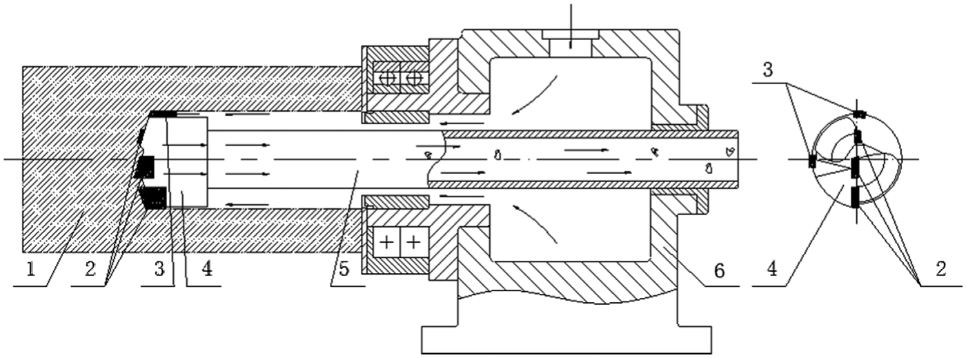
Existing deep-hole cutting tool and its fluid flow.
Guidance principle of existing deep-hole cutting tools
The guidance principle of existing deep-hole cutting tools can be determined from Figure 1. The guidance is based on the deep-hole wall and the guide pads relative to the resultant forces. The guide pads and one side of the wall of the deep hole are in contact, so the deep-hole cutting tool follows the machined surface of the deep-hole wall. The asymmetric construction of the deep-hole cutting tool and its guidance principle was developed approximately 200 years ago. 1
Based on the existing guidance principle, Matsuzaki et al. 8 increased the number of guide pads. Kong and colleagues9–11 analyzed the dynamic behavior of the drilling shank. Biermann et al. 12 produced a cutting simulation. Al-Wedyan and Hayajneh 13 studied the property of machining dynamics. Biermann et al. 14 optimized the guide pads of deep-hole drills. Al-Ata and Hayajneh 15 discussed the issues of bell-mouths in deep holes.
In recent years, to solve deep-hole machining problems with special structures, special size, and special materials, researchers have applied optical, electrical, and ultrasonic techniques to deep-hole machining. Zhu et al. 16 studied the deep-hole electrodischarge drilling. Brajdic et al. 17 analyzed the deep holes drilled by laser. Liew et al. 18 explored the ultrasonic vibration deep-hole machining. Bilgi et al. 19 used the electrochemistry deep-hole drilling. However, the above methods are unsuitable for machining ordinary deep holes. Currently, the existing guidance principle of deep-hole cutting tools is still the main technical principle of deep-hole machining.
Disadvantages of existing guidance principle of deep-hole cutting tools
The existing guidance principle has disadvantages. First, the cutting tool structure is asymmetric and the resultant cutting force is not zero, so the workpiece will bend and distort, which will influence the diameter and straightness of the deep hole. This is especially true with low-stiffness workpieces. In contrast, symmetric cutting tools, such as a twist drill, will not make the workpiece bend due to the cutting tool itself. Second, because the cutting tool is asymmetric, when it rotates, the processing system will vibrate, make noises, and generate an unnecessary centrifugal force.20,21 Third, because the two guide pads act tightly on the hole wall, they will cause significant friction forces and induce pad wear. Simultaneously, power dissipation will increase significantly. Fourth, apart from cutting edge failure, the failure of guide pads will make deep-hole machining impossible. Fifth, defects of the machined surface of the deep-hole wall will very likely cause the cutting tool and the entire deep hole to deviate from their proper position. Therefore, many researchers have tried to overcome the above disadvantages. 22
Fluid flow in existing deep-hole cutting tools
Drilling or boring to make deep holes is usually done using cutting fluid (oil or coolant). The functions of cutting fluid are to remove chips, to cool the tool and workpiece, and to lubricate the tool.23,24
Figure 1 shows the fluid flow in the existing deep-hole cutting tool. The fluid flow is similar to that in the product sample from Botek™, USA, Inc. 25 The cutting edges and guide pads are fixed in the hollow steel body to form the tool diameter. The hollow steel body diameter must be slightly smaller than that of the complete tool to allow passage of the cutting fluid (oil or coolant). The hollow steel body is screwed on to the shank thread hole. The shank diameter is smaller than that of the deep hole to allow for passage of the cutting fluid.
The cutting fluid flows past the outside of the shank, cools the tool and workpiece, and drives the chips out. The chips exit through the hollow steel body and the interior of the shank.
Fluid wedge effect and hydrodynamic lubrication of journal bearings
Unlike Figure 2(b), Figure 2(a) does not show the fluid wedge effect. In Figure 2(a), the moveable and stationary plates are parallel. The space between the two plates is full of oil, which is a Newtonian viscous fluid. The top plate moves at a speed of v. Because of the oil viscosity, the velocity variation is linear from 0 to v. The oil thickness between the two plates is the same, which does not create a pressure in the oil film to support a load.
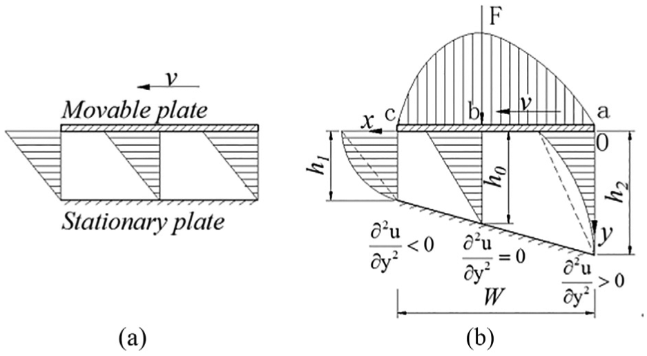
Velocity and pressure distributions in the oil film between two plates: (a) oil film with constant thickness and (b) wedge-shaped oil film.
In Figure 2(b), the top plate moves with a velocity v in the x direction on a film of oil. The stationary surface of the lower plate has a zero velocity. As shown in Figure 2(b), the pressure in the oil film increases initially, reaches a maximum, and then decreases. Because the oil film pressure in the wedge-shaped space is higher than the oil film pressure at the entrance and exit, the oil film can support a load F. p is the pressure in the oil film.
Equation (1) can be derived from Figure 2 and is the classical Reynolds equation for one-dimensional flow (assuming that the oil is incompressible)
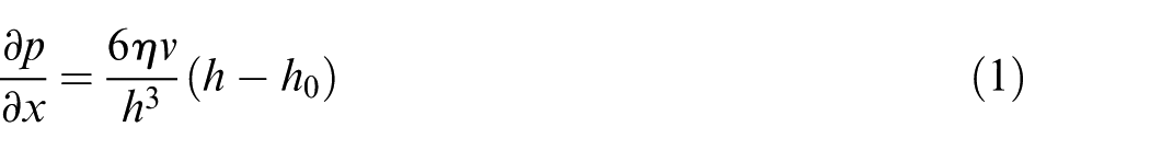
where
As shown in Appendix 1, equation (2) is proven from Figure 2
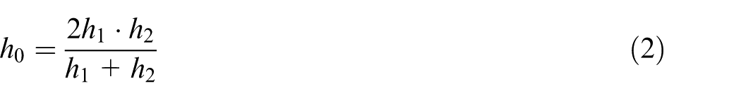
where
Problems of deep-hole machining
The following problems exist during deep-hole machining. First, deep-hole cutting tool deviation occurs often, which influences the machining precision, and can even render the workpiece useless. Second, during deep-hole machining, it is difficult to observe the position and state of the cutting tool and the deep hole. Third, if the machine tool is not stopped, it is impossible to correct the deviation of the deep-hole cutting tool. To overcome the disadvantages of the existing guidance principle of deep-hole cutting tools, a novel guidance principle is proposed in this article.
Guidance principle of deep-hole cutting tools based on fluid wedge effect
A “guidance principle of deep-hole cutting tools based on the fluid wedge effect” is proposed in this article. This novel guidance principle makes the deep-hole cutting tool to move forward along the axis of the deep hole by the action of the fluid.
Deep-hole cutting tool with a wedge-shaped body
The key of the novel guidance principle is the deep-hole cutting tool with a wedge-shaped body as shown in Figure 3. The greatest difference between Figures 1 and 3(a) is that in Figure 3(a), there is a wedge-shaped body (7) and the wedge-shaped body (7) has four eccentric arcs.
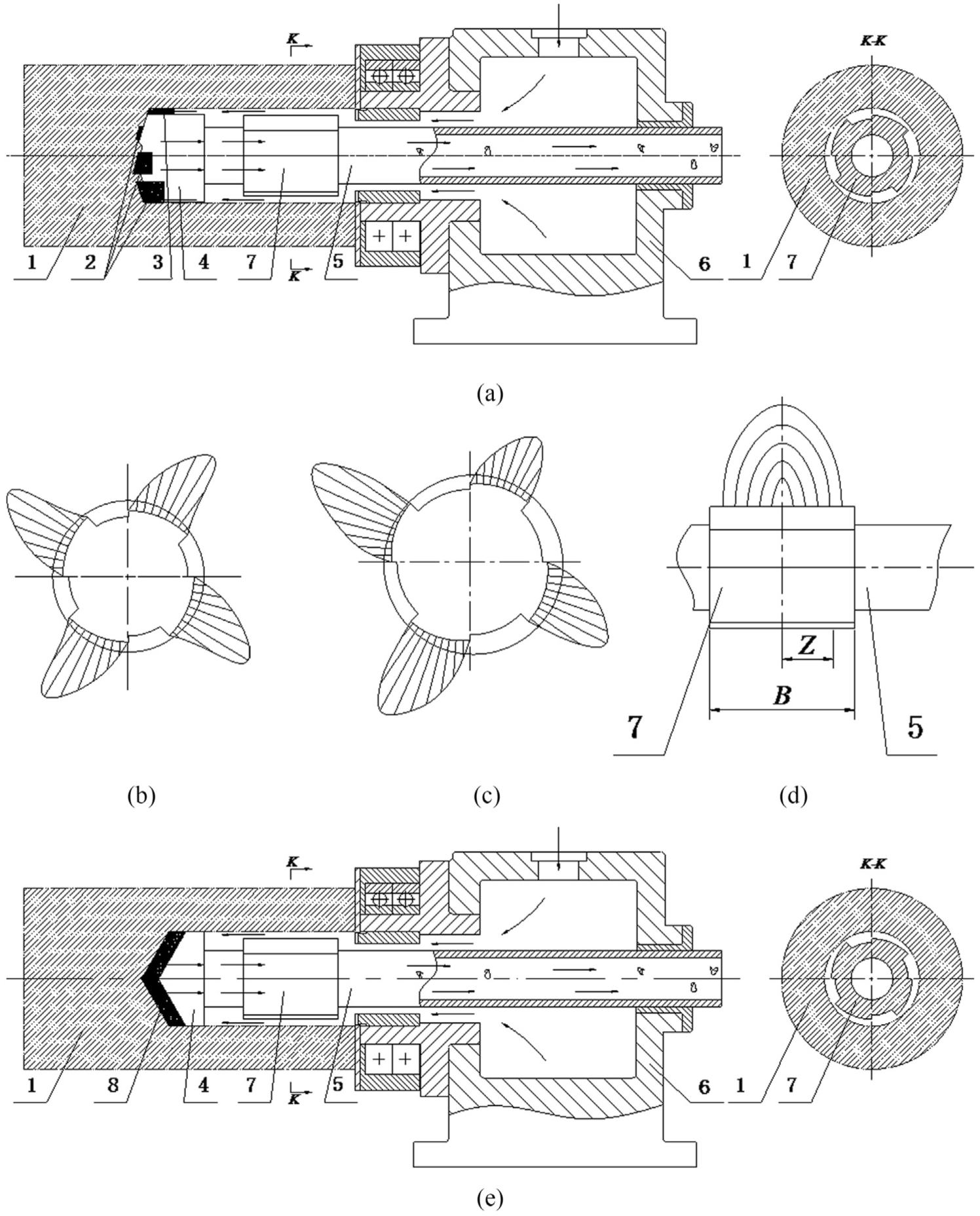
Schematic diagram of guidance principle of deep-hole cutting tool based on fluid wedge effect: (a) deep-hole cutting tool with a wedge-shaped body, (b) circular oil pressure distribution (
Guidance principle based on fluid wedge effect
The guidance principle based on the fluid wedge effect is derived from hydrodynamic lubrication bearings and is shown in Figure 3.
In Figure 3, the K–K view shows that the wedge-shaped body (7) and the wall of the deep hole form four wedge-shaped spaces. The workpiece rotates relative to the wedge-shaped body. The cutting oil is drawn into the four wedge-shaped spaces to form the four wedge-shaped oil films.
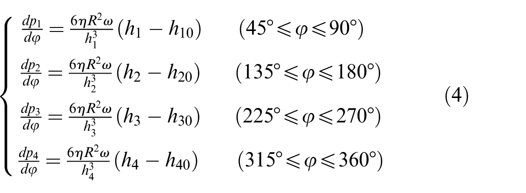
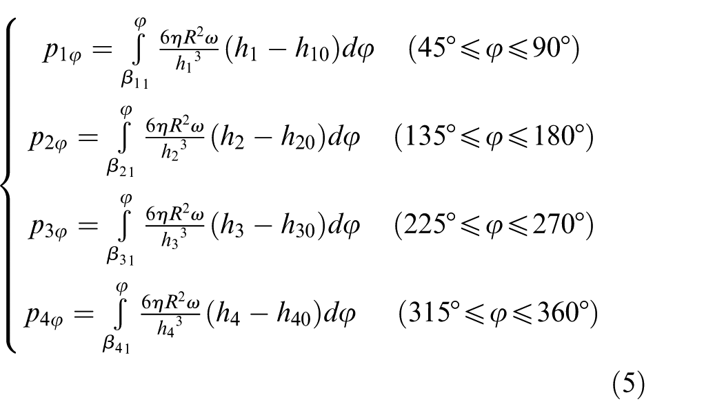
The pressure distribution of the oil film along the circle in Figure 3(b) can be derived from the classical Reynolds equation (see equation (1)). 26 As shown in Figure 3(b), the oil film pressure in the wedge-shaped space is higher than the oil film pressure in the inlet and the outlet.
The four wedge-shaped oil films are equidistantly spaced, so they act on the wedge-shaped body just as a three- or four-jaw chuck clamps a workpiece. The forces of the four wedge-shaped oil films force the wedge-shaped body along with the drill tip and the shank to be centered in the machined deep hole. The deep-hole cutting tool moves forward along the axis of the machined deep hole.
According to the “guidance principle based on the wedge effect,” deep holes can be machined with symmetric (see Figure 3(e)) or asymmetric cutting tools. Figure 3(e) shows a deep-hole cutting tool with a symmetric structure. If the forces of the four wedge-shaped oil films are sufficiently large, the four oil films also force the wedge-shaped body along with the drill tip and the shank to be centered in the machined deep hole and to move forward along the axis of the machined deep hole.
When the cutting tool has the usual asymmetric structure (Figure 3(a)), the four wedge-shaped oil films act on the cutting tool system in the same manner as a three-jaw chuck clamps the workpiece. If the cutting tool moves along the axis of the deep hole, the resultant force created by the four oil films is zero. If the cutting tool deviates from the axis of the deep hole (Figure 3(c)), the resultant force created by the four oil films is not zero, and the resultant force tends to reduce the deviation of the cutting tool. In addition, because of the support of the oil film, the wedge-shaped body helps to improve the stiffness and stability of the cutting tool system.
The number of eccentric arcs or wedge-shaped spaces can be designed as 3 to 5. Because the oil films support the cutting system, the guidance principle of the deep-hole cutting tools based on the fluid wedge effect is different from the existing guidance principle and is a novel invention. 29
Parameters of the wedge-shaped body and oil films
Figure 4 shows the structure of the wedge-shaped body. In Figure 4, four arcs exist in the wedge-shaped body. The oil films corresponding to arcs 1, 2, 3, and 4 are defined as the first, second, third, and fourth oil films.
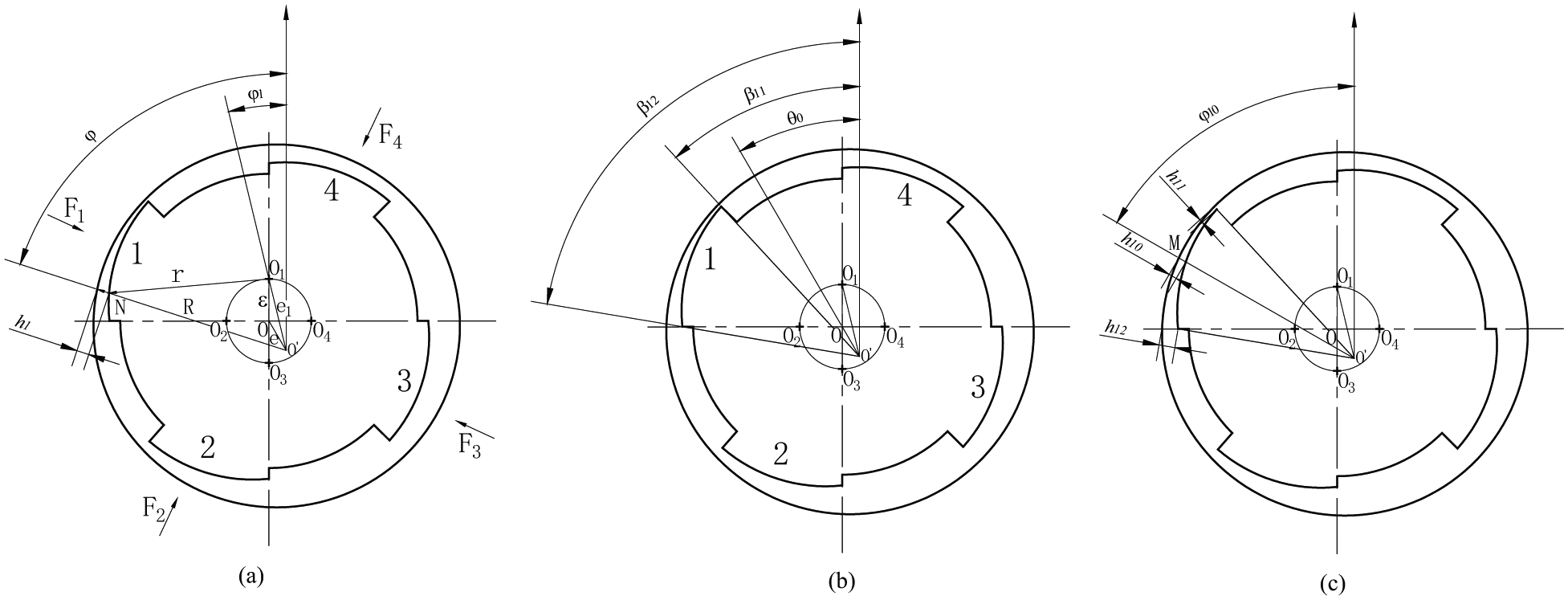
Structure of a wedge-shaped body: (a) radii and related parameters, (b) angles and related parameters, and (c) film thicknesses and related parameters.
In Figure 4(a), O is the center of the wedge-shaped body and
O1 is the center of arc 1 of the wedge-shaped body. O2, O3, and O4 are the centers of arcs 2, 3, and 4, respectively. In Figure 4,
In Figure 4(a), for arc 1,
The maximum pressure occurs at point M. Likewise, as for arcs 2, 3, and 4, we can also define
The cutting tool rotates relative to the workpiece, and
B = 60 mm,
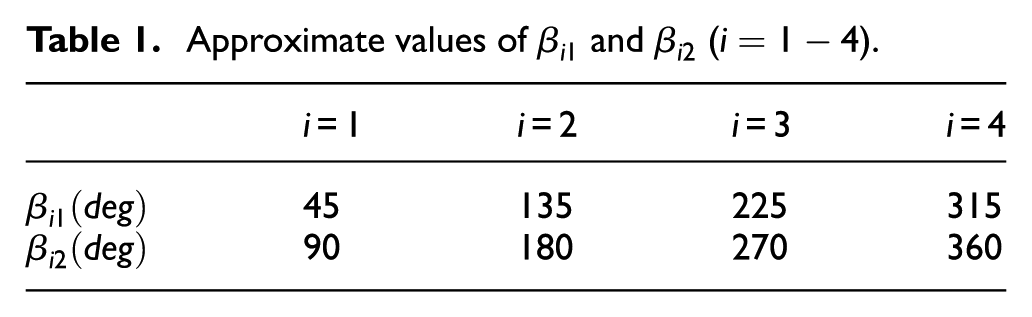
Approximate values of
Analysis and calculation of forces of wedge-shaped oil films
Analysis of forces of wedge-shaped oil films
The force of the oil film in a deep hole is similar to that in the hydrodynamic lubrication bearing, and it depends on (1) the clearance between the deep hole and the wedge-shaped body, (2) the relative rotational speed between the deep hole and the wedge-shaped body, and (3) the viscosity of the cutting oil.
For a deep hole with a large diameter, the relative velocity between the workpiece and the cutting tool is high, which will create a high oil pressure to support and guide the cutting tool. For a deep hole with a small diameter, the relative velocity between the workpiece and the cutting tool is low, which will not create a high oil pressure. In this case, wedge-shaped oil films can still support the cutting tool because the supporting capacity needed to machine a deep hole is lower than that in the hydrodynamic lubrication of a sliding bearing. For example, the former may be 500 N, whereas the latter may be 5000 N. In addition, deep-hole machining is advancing toward high-speed cutting. The oil viscosity and supply can be met easily in deep-hole machining.
Calculation of forces of wedge-shaped oil films
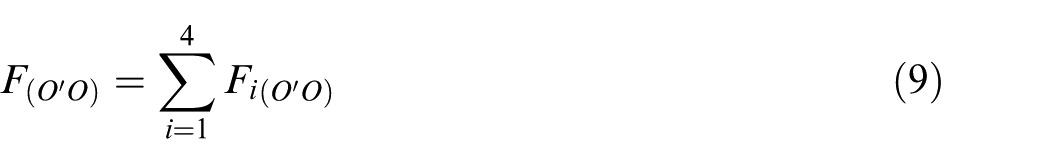
Resultant force of wedge-shaped oil films
The resultant force of oil films tends to rectify the deviation of a cutting tool.
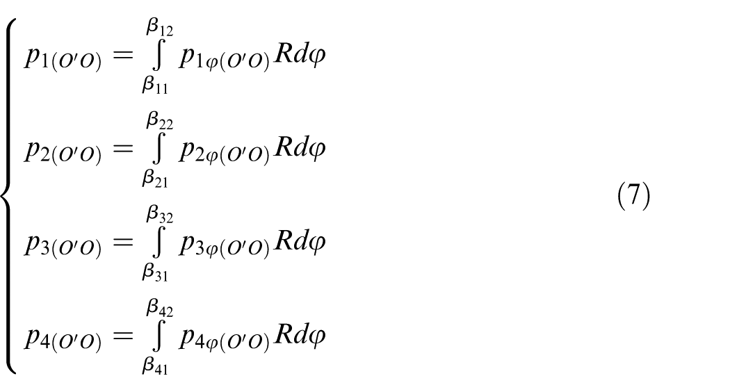
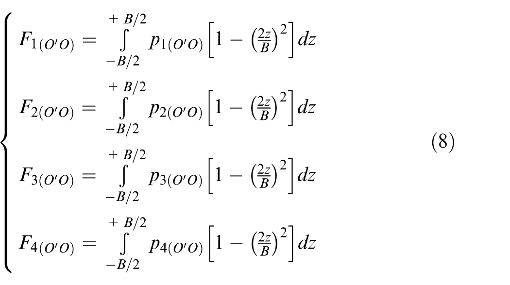
Equation (3) is proven in Appendix 2 based on Figure 4
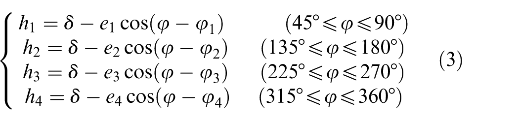
Similarly, as for arcs 2, 3, and 4, define


In ideal cases, if
In Figure 4,
then
The positive direction is from
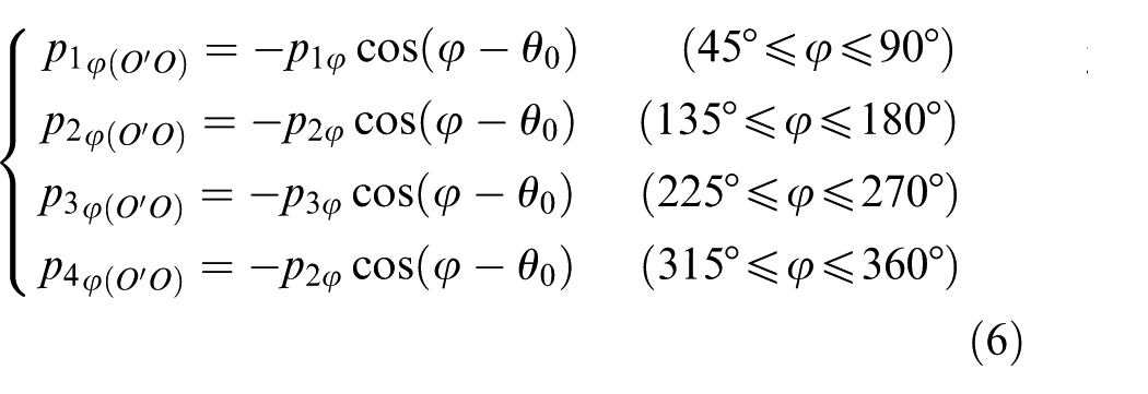
then
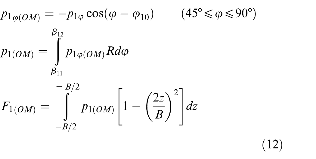
As shown in Figure 3(d), the curve of the pressure distribution in the oil film is axially a parabola, 26 so
Example 1
Objective: to calculate the resultant force of oil films,
Given: in Figure 4
R = 37.7 mm, r = 36.86 mm, and
Other parameters have been introduced in section “Parameters of the wedge-shaped body and oil films.”
Solution: the solution is provided in Table 2.
Calculated parameters of designed wedge-shaped body.
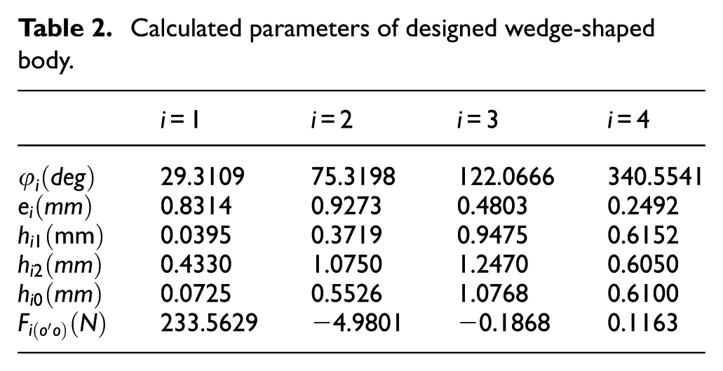
Result:
Figure 5 shows that as “e” increases,
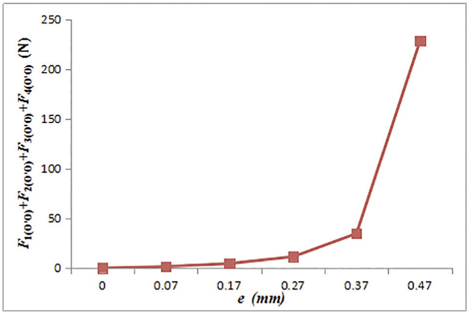
Resultant force of oil film (
Force of each wedge-shaped oil film
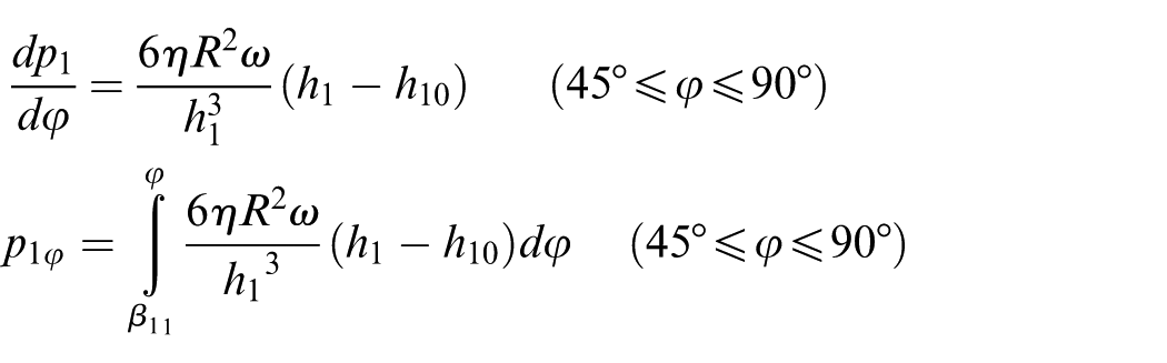
In Figure 4, when
In Figure 4,
In equation (3), let

Equation (11) can be derived from equation (10)
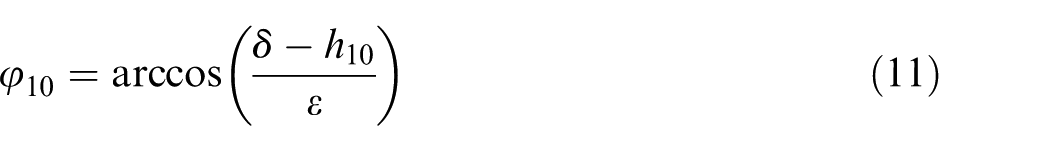
In Figure 4,
The positive direction is from O to M. (Note:
Example 2
Objective: to calculate the force of each oil film,
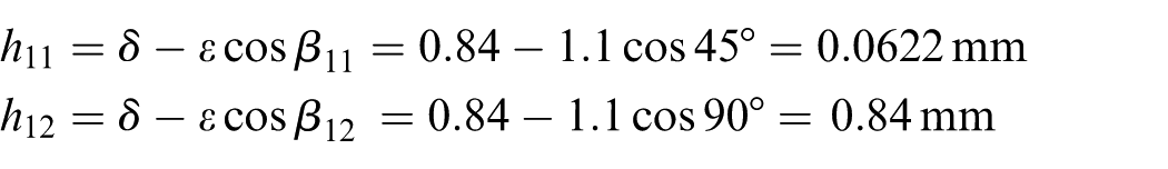
Given: in Figure 4
e = 0 and
R = 37.7 mm, r = 36.86 mm, and
Other parameters have been introduced in section “Parameters of the wedge-shaped body and oil films.”
Solution:
From equation (10), we get
From equation (2), we get
From equation (11), we get

Result:
Figure 6 shows that as
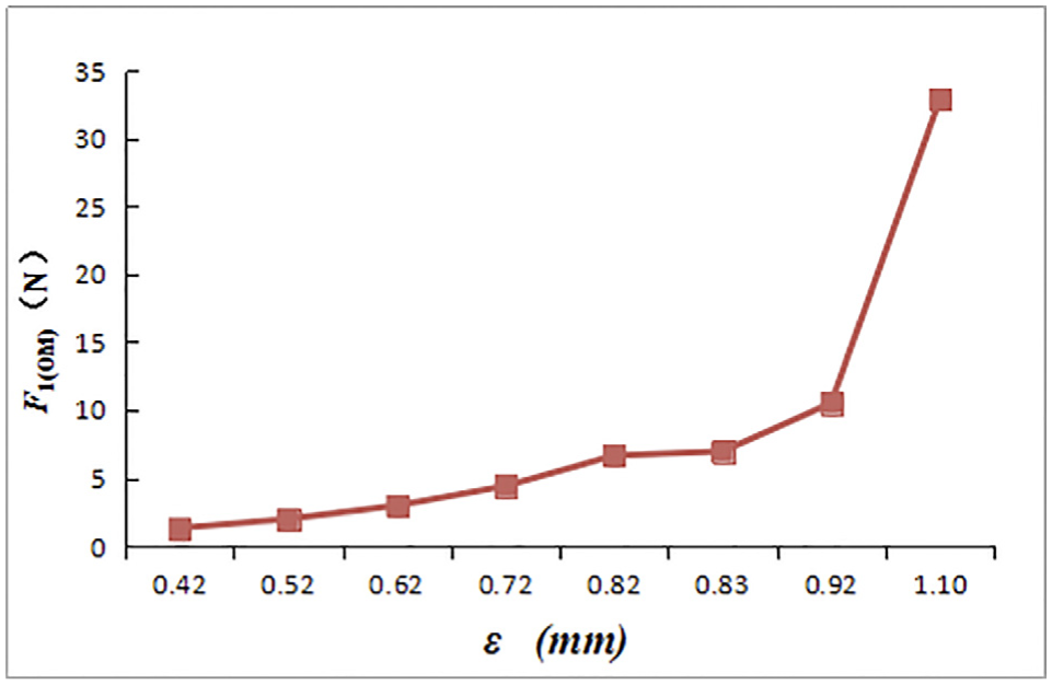
Force of the first oil film (
Example 3
Objective: to calculate the force of each oil film,
Given: in Figure 4
e = 0 and
R = 37.7 mm, r = 37.5 mm, and
Other parameters have been introduced in section “Parameters of the wedge-shaped body and oil films.”
Solution:
From equation (10), we get


From equations (2) and (11), we get

Result:
Experiments
Figure 7(a) shows the existing deep-hole cutting tool, and Figure 7(b) shows the proposed deep-hole cutting tool and the novel guidance principle. The workpiece was 6.3 m long and its outside diameter was 190 mm. The deep hole in the workpiece was a through-hole of 75.4 mm diameter.
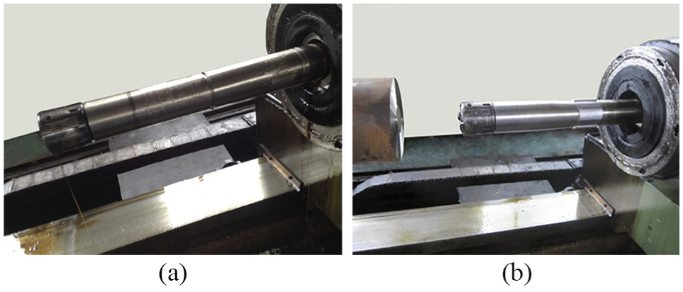
(a) Existing deep-hole cutting tool and (b) proposed deep-hole cutting tool and novel guidance principle.
The wedge-shaped body had four eccentric arcs in Figure 7(b). During drilling, wedge-shaped zones and films were formed by the wedge-shaped bulges and the wall of the machined deep hole; sufficient oil was supplied to drive the chips out.
Figure 8 shows the equipment required to measure the straightness of a deep hole. A measuring head with a position-sensitive detector was inserted into the deep hole and was driven to move along the deep hole. A laser emitted a beam toward the position-sensitive detector. The facula was used to measure the straightness of the deep hole. The electrical signals of the facula were converted and displayed as dimensions with a digital readout outside the deep hole.
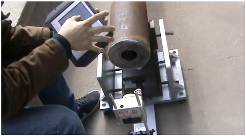
Equipment used to measure the straightness of a deep hole.
Group one
The experimental design is the same as that described in Example 2. The experimental results by the novel cutting tools are shown in Figure 9.
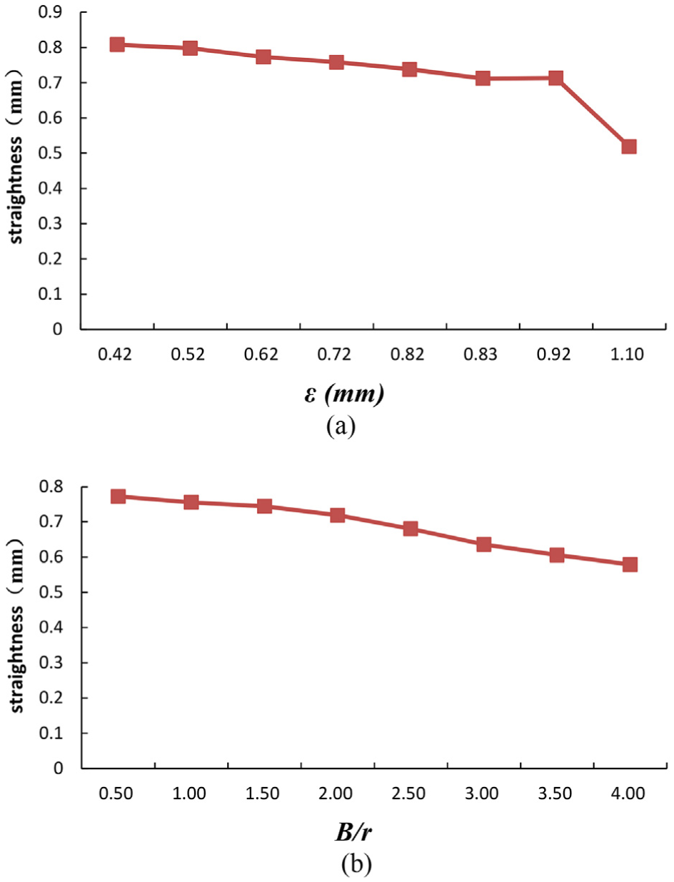
(a) Straightness of deep hole versus
As the center distance
In Figure 9, the mean value of the straightness of deep holes was less than 0.8 mm. In contrast to the experimental results in Figure 9, the mean value of the straightness of the deep holes machined by the existing cutting tool was more than 1.1 mm.
Group two
The experimental design is the same as that described in Example 3.
The mean value of the straightness of the deep holes that was machined by the proposed cutting tool was 0.485 mm, which was 0.323 mm less than that machined by the existing cutting tool.
Despite the existence of group one or group two, the mean value of the roundness of the deep holes machined by the proposed cutting tool was 0.008 mm, which was less than that achieved by the existing cutting tool.
The surface roughness of the deep holes as machined by the proposed cutting tool was 1.6 µm, which approximated the one achieved with the existing cutting tool.
Conclusion
The following conclusions can be drawn according to the above research:
The existing guidance principle of the deep-hole cutting tools has been used for more than 200 years. Most deep holes are machined using this principle. The deep-hole cutting tool follows one side of the deep-hole wall because of asymmetric construction. Although the existing deep-hole machining principle has its advantages, the deviation of the deep hole is a difficult problem that needs to be addressed.
The guidance principle of deep-hole cutting tools based on the wedge effect stems from the hydrodynamic lubrication in journal bearings and can prevent the deviation of deep-hole cutting tools during machining. The key of the novel guidance principle is the wedge-shaped body. The wedge-shaped body was invented and is fixed to the drill tip and the shank. Four wedge-shaped oil films exist, which act on the wedge-shaped body just as the three-jaw chuck clamps a workpiece. The forces of the oil films make the wedge-shaped body with the drill tip and the shank be centered in the machined deep hole, and the wedge-shaped body moves forward along the axis of the machined part of the deep hole.
If the cutting tool does not deviate from the axis of the deep hole, the resultant force created by the four oil films is zero. If the cutting tool deviates from the axis of the deep hole, the resultant force created by the four oil films is not zero, which will reduce the deviation of the cutting tool automatically.
The novel guidance principle for deep-hole cutting makes the tool to move along the axis of a deep hole. The existing guidance principle for cutting tools allows for movement along one side of the wall of a deep hole. Therefore, this novel principle yields a higher machining precision.
Experiments showed that the deep hole that was machined by the novel guidance principle was straighter than that obtained by the existing cutting tool. The parameters of the wedge-shaped body influenced the force of the oil film and the straightness of the deep holes.
The guidance principle based on the fluid wedge effect may provide a solution to the difficult problem of cutting tool deviation in deep-hole machining.
Footnotes
Appendix 1
Appendix 2
Declaration of conflicting interests
The author(s) declared no potential conflicts of interest with respect to the research, authorship, and/or publication of this article.
Funding
The author(s) disclosed receipt of the following financial support for the research, authorship, and/or publication of this article: This research was supported by the Natural Science Foundation of China (Grant No. 51175482) and the Achievement Foundation of North University of China (Grant No. 201602).