
Abstract
The welding distortions of large-scale structures are extraordinary complicated. If an effective tool of predicting welding distortion is available, then marine design and manufacturing engineers can use this to improve production quality and reduce costs. This article focuses on the comparative studies of welding procedure of a stiffened panel. An efficient thermal elasto-plastic finite element method–based procedure is developed to predict the welding deformation and residual stress of structures. A combined shell/solid model is adopted to enhance modeling and calculation efficiency. The welding process of a stiffened panel is simulated. Three welding procedures of simultaneous, successive and bidirectional welding are studied. The results show that welding distortion can be well controlled by adjusting the welding procedure.
Introduction
Stiffened plate panels are elementary units in structures of naval and merchant ships. Arc welding is the primary means of attaching stiffeners to the plate of panel. The non-uniform expansion and contraction of materials in welded structure cause unavoidable welding residual stresses and deformation. Out-of-plane distortion induced by welding can be observed even at very early stages of plate fabrication and keep developing at subsequent ones.
Some recent work has highlighted practical techniques to control and mitigation welding deformation. 1 Numerical approaches can serve as effective tools in assisting designers to optimize the fabrication process. In recent years, various finite element models of welding have been developed. Deng and Murakawa 2 proposed a prediction and evaluation system of welding distortion based on inherent strain theory of elastic finite element method (FEM). The contributions of each joint for the distortion were determined by the thermal elasto-plastic finite element analysis and using interface elements. Through the system, the buckling distortion induced by welding in thin plate panel structures was predicted and the influences of several factors on buckling were investigated. Wang et al. 3 applied elastic finite element analysis based on inherent deformation theory to bead-on-plate welding and thin plate welded structures to investigate the mechanism of welding-induced buckling. Eigenvalue analysis was performed to obtain the critical tendon force of buckling modes. Mun and Jang 4 improved the inherent strain analysis method by incorporating heat equivalent layer effects into the heat conduction analysis. More accurate predicted results of welding deformation of a hull panel block were obtained by applying constraint level to the final equivalent load on the block. Bachorski et al. 5 developed a shrinkage volume approach, which assumes that linear thermal contraction is the main driving force for welding distortion, to predict post-weld distortion. The use of linear elastic FEM permits large, highly complex welded structures to be modeled within a reasonable time frame.
Camilleri et al. 6 suggested a computationally efficient method (CEM) for modeling welding processes. The thermo-mechanical welding process was separated into thermal transient, thermo elasto-plastic and final structural elastic stages. In the first stage, transient thermal distributions were established through analytical or numerical approaches. A thermal transient solution based on a two-dimensional cross-section of the weld was sufficient to acquire accurate temperature fields. In the thermo elasto-plastic stage, algorithms of mismatched thermal strain (MTS) and thermal contraction strain (TCS) were adopted to estimate longitudinal and transverse thermal strains, which associate the thermal welding strains with the structural elastic response of the welding. A butt welded plate 7 and thin plate with fillet-welded stiffeners 8 were modeled to investigate strategies for computationally efficient welding simulation in the context of predicting welding deformations. The experiment of a stiffener attached to a large plate through fillet welds was performed to study the extent to which the experimental determination can be simulated using the simplified model. 9
Thermal elasto-plastic FEM provides a more comprehensive route to simulate welding processes. Various key welding factors and special weld details can be dealt with in it. Deng et al. 10 performed experimental and numerical simulations to investigate the welding residual stress distribution in medium thick-walled austenitic stainless steel pipe. The temperature field and residual stress were predicted using a 2D axis-symmetric thermal elasto-plastic FEM computational procedure. Kiyoshima et al. 11 developed a method of thermal elasto-plastic FEM based on variable length heat sources for the analysis of thermo-mechanical behaviors for multi-pass joints. The residual stress field in a dissimilar metal J-groove joint with axis-symmetric geometrical shape was investigated using the proposed approach. The influences of the heat source model on welding deformation and residual stress were discussed. Chen et al. 12 studied the influence of welding sequence on distortion and residual of a large stiffened plate structure by an improved thermal elasto-plastic FEM. The welding directions and sequences of longitudinal stiffeners were shown to have a significant effect on welding distortions. Park and An 13 proposed a model of joint rigidity method to investigate the effect of welding sequence on fillet welding distortion. Both experimental and simulation results demonstrate the differences of welding distortion under different sequences. The parametric studies of traveling arc, welding start/stop and welding sequence in the circumferential direction on residual stress distribution in a thin-walled pipe weld were investigated by Lee and Chang. 14 The results show that the residual stresses within and near the weld deposit are general influenced by the welding sequence. Residual stress of repair welds was studied by Dong et al.15,16 using computational modeling procedures and experimental techniques. The distribution and magnitude of residual stresses were predicted through 3D shell modeling and the important general features of the repair residual stress fields were identified.
Proper welding procedure is one of the key process-related factors which influence distortion of structures. This article concentrates on a comparative study of deformations in a stiffened panel owed to different directions and sequences of fillet welds. A new efficient analytical modeling for the simulation of welding process is established. An improved procedure is suggested based on the simulation results to ameliorate the distortion and stress distribution of the structure.
Welding procedure
Welding-induced distortions of structures are influenced by design-related and process-related factors. 17 Design modifications such as increasing base plate thickness and reducing stiffener spacing can increase bending stiffness of structure and thus resist the contraction forces developed through welding. Variations in fabrication procedures too are found to have significant effects on distortion. Deng and Murakawa 2 demonstrated the difference of the welding distortion and residual stress of a thin plate panel under simultaneous and sequential fabrication procedures. Tack weld spacing, support and clamping conditions and welding sequences can also be optimized to minimize welding distortion. 18
Welding procedure is one of the primary factors affecting residual distortion and stress of welded thin plate structures. This study addresses the directions and sequences of fillet welds during attachment of a stiffener to the plate. Figure 1 illustrates the three welding procedures considered in the present work. In this figure, the arrows represent the direction of movement of the welding torch. The solid lines in arrows indicate the first welding pass on one side of fillet weld and dashed lines indicate the next pass on the other side after cooling of the previous weld. For simultaneous welding, welding passes on both sides of the fillet are performed simultaneously in the same direction. In the case of successive welding, the first welding pass is implemented on the left side of a tee joint and the second pass is done on the right side after cooling of the first weld. The principal differences between successive and bidirectional welding are the direction and start and end points of the second welding pass, as shown in Figure 1(c).
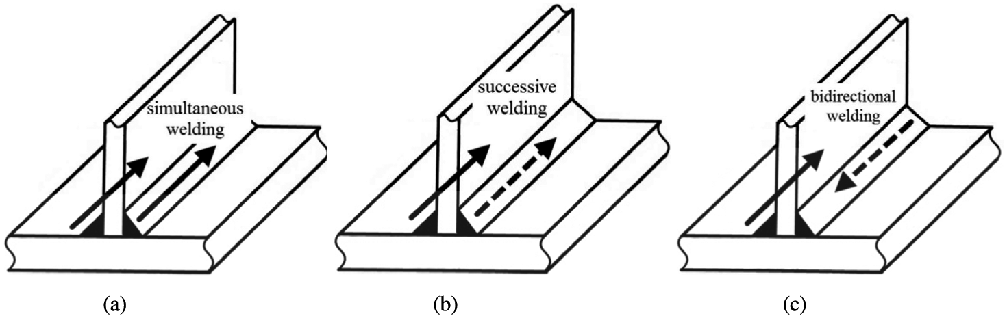
Welding procedure: (a) simultaneous welding, (b) successive welding and (c) bidirectional welding.
Stiffened panel case
A stiffened panel is selected as the study object in this article. The structure consists of a 6-mm-thick plate and five longitudinal stiffeners, see Figure 2. The lateral dimensions of the plate are 2688 × 2400 mm. The stiffeners are tee types with a spacing of 480 mm. The widths of the web and flange of stiffeners are 80 and 40 mm, respectively. The web and flange thickness of the stiffeners is 8 mm. The material of the stiffened panel is EH36 steel.
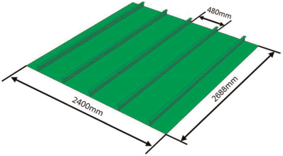
Structural geometry.
All stiffeners are joined to the plate by double-sided fillet welds using CO2 gas metal arc welding. The welding current is assumed as 270 A and voltage is 26 V. The welding speed is taken to be 8.0 mm/s. The efficiency of heat input is assumed as 0.75. The leg length of the fusion zone is 6 mm. Figure 3 shows the three welding cases considered in this study. In this figure, the symbols S1 to S5 indicate the sequence of stiffeners being welded. All cases have the same welding sequence of stiffeners. The first stiffener to be welded is the middle stiffener and the last or fifth stiffener to be welded is the one on the extreme right. The numbers 1 to 5 indicate the order of welds and the arrows indicate the direction. For example, in the case of WS1, the two welds for every stiffener are carried out simultaneously. The arrows indicate the direction of the weld which, in this case, is from the one to another edge of stiffeners. Now consider the case of WS3. Here, the two welds for every stiffener are carried out bidirectionally. The first weld starts from the one to another edge of stiffeners and the second weld proceeds back and so on. Similarly, one can deduce the welding sequences and directions for WS2.
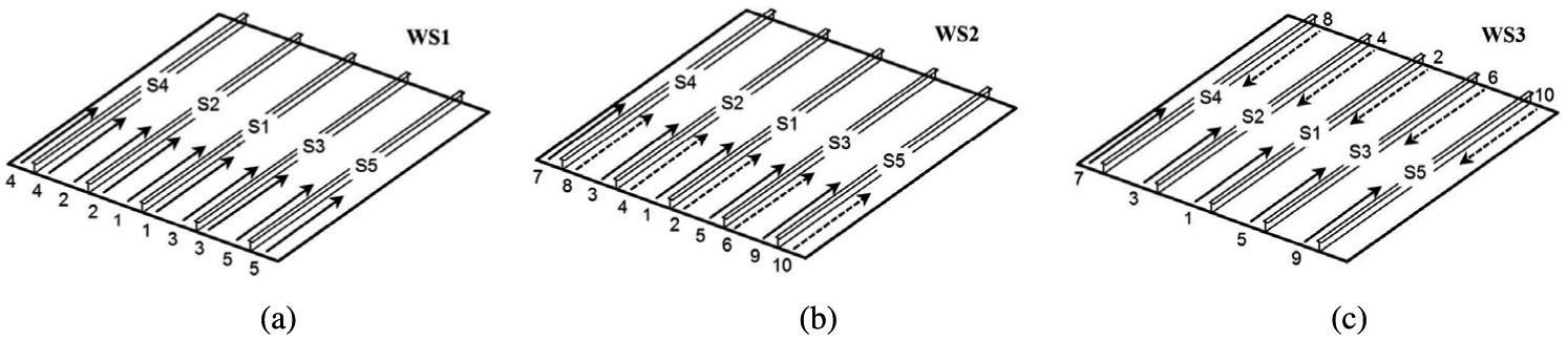
Welding cases: (a) WS1, (b) WS2 and (c) WS3.
Finite element implementation
Numerical approach
Welding simulation can be decomposed into two steps of thermal and mechanical analyses. A sequentially coupled thermal elasto-plastic FEM is adopted in this study. In the thermal analysis, the transient temperature distributions are calculated according to equation (1)
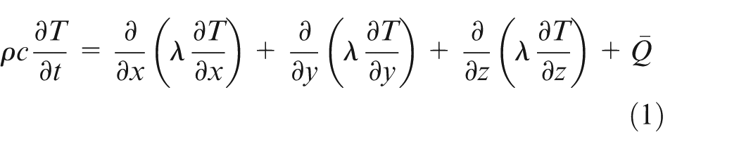
In equation (1), T represents the temperature; ρ, c, λ are the density, specific heat capacity and the thermal conductivity of material, respectively;
Temperature field results obtained from the thermal analysis are the inputs for the mechanical analysis model. Thermal expansion and shrinkage of material in the heat cycle of welding induce welding deformations and residual stresses in the structure. The total strain increments can be decomposed into several components as equation (2)

where
FE model
Numerical simulation of the welding process of the stiffened panel is implemented using the commercial FE code Abaqus/Standard. In order to enhance the efficiency of calculation and decrease the complexity of modeling, a shell/solid model is adopted in thermal analysis. Shell elements with section integration (SESI) 19 are introduced to realize three-dimensional heat transfer. The welded plates are modeled by shell elements and several temperature integration points are set through the shell thickness at the nodes of shell elements. Temperature at any position in a shell element can be obtained through nodal temperature values and the interpolator in the reference surface and through thickness. Weld feet are modeled by solid elements. The degrees of freedom at the contact surface between welded plates and feet are related by linear constraint equations. The equations make the temperature consistent between shell and solid elements and realize the heat energy conduction effectively. Thus, the high temperature gradient in fusion zone can be described precisely by the shell/solid model. The temperature fields of welding process are exerted on the mechanical model of shell elements as external loads after the thermal analysis. Due to much less degrees of freedom in shell/solid model than that in entire solid model, the computational efficiency of the former enhances significantly.
A fine mesh is used in heat-affected zone (HAZ) and the dimensions of both shell and solid elements are about 2 mm × 4 mm. In the light of a low temperature gradient outside HAZ, a relatively coarser mesh is sufficient in terms of accuracy. Previous research12,19 demonstrates that this kind of meshing strategy is suitable for the welding simulation of the stiffened panel. The same mesh is employed in the thermal and mechanical models. There are 99,330 shell elements, 49,280 solid elements and 187,968 nodes in model. In order to reduce computing time for the thermal analysis, the substructure including one entire stiffener and surrounding plate is used to simplify calculation scale when the stiffener is welded. The boundary conditions of the mechanical model are shown in Figure 4.
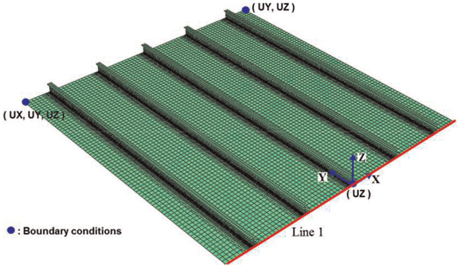
Boundary conditions of the FE model.
The material of the structure is EH36 high strength steel and the temperature-dependent properties are shown in Figure 5. A transient moving heat source with Gaussian surface and uniform volumetric distribution is adopted in the heat transfer analysis. The description of heat source model can be found in Chen et al. 12 The convection boundary condition is set on the surface of the structure in thermal analysis. The convection coefficient of heat transfer is assumed as 15 × 10−6 W/(mm2 °C) considering heat loss due to convection under free air condition and radiation is ignored in thermal analysis. The ambient temperature is assumed to be 20°C.
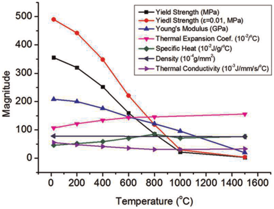
Material properties.
Verification of accuracy
The comparative studies between experimental and numerical results of a tee joint weld are carried out to verify the accuracy of the approach. The experiment is implemented by Deng et al. 20 in order to investigate the characteristics of welding deformation in fillet joint. Figure 6 shows the experimental configuration of the tee joint. The length and breadth of the flange are 500 mm. The height of the web is 300 mm. The thickness of the flange and web are 12 and 9 mm, respectively. The tee joint is tack welded by 10 mm short bars before two-sides successive welding performed. The welding parameters are as follows: welding current I = 270 A, voltage U = 29 V and welding speed v = 400 mm/min. The welding deflection at lines A-A, B-B and C-C are measured in the experiment by a three-dimensional photograph measurement. Targets on the upper surface of the flange are used to measure coordinates before and after welding. The deflection at each location is calculated through these coordinates. Angular deformation of the fillet joint can be obtained from the vertical deflection at three lines.
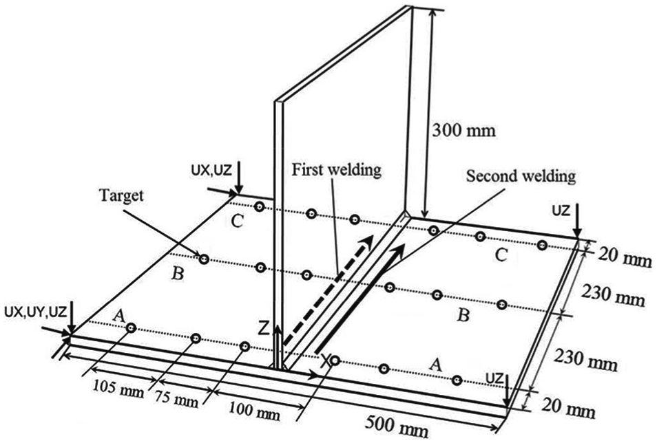
Experiment configuration.
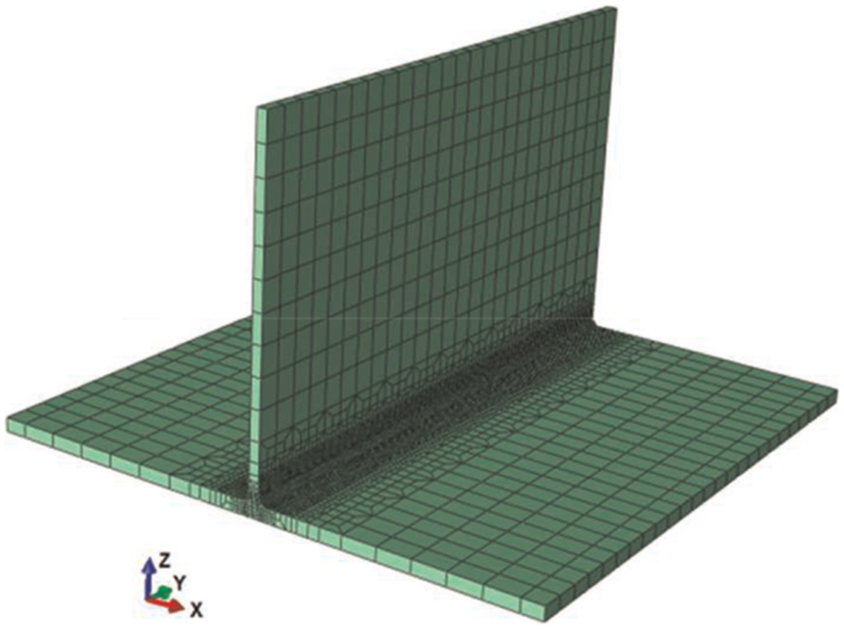
FE simulation using same approach to the study object is carried out according to the experimental setup. Two kinds of models, including shell/solid model (as shown in Figure 7) and solid element model (as shown in Figure 8), are adopted to simulate the welding process. Meshing strategy of experimental fillet joint is similar to the stiffened panel.
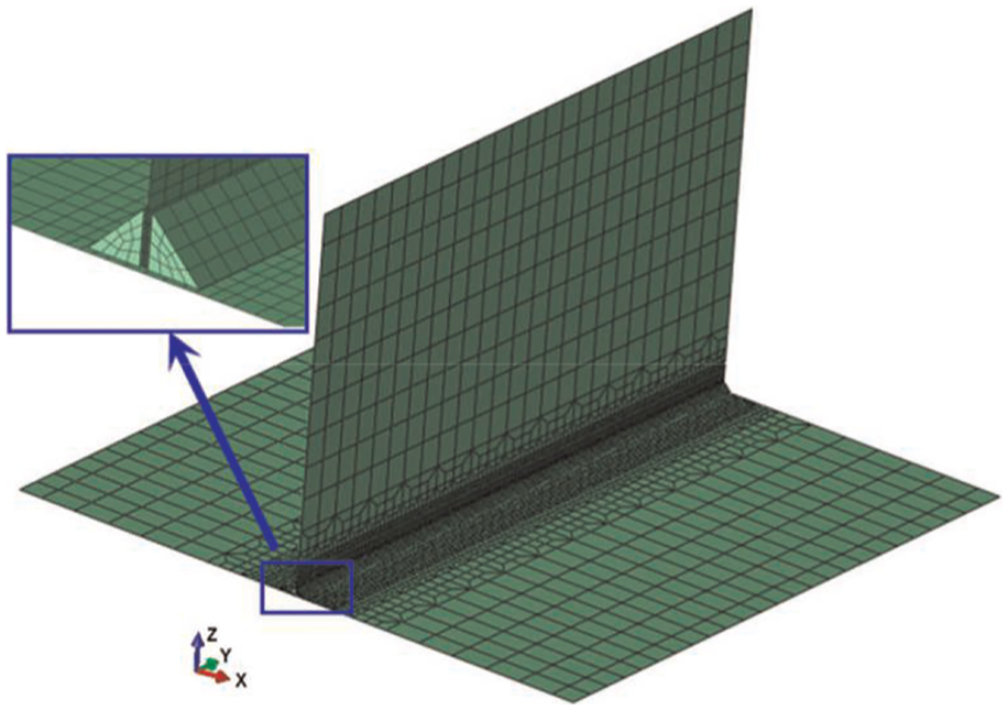
Shell/solid model.
Solid model.
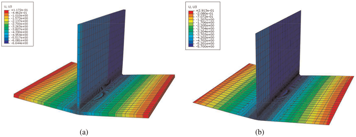
Temperature distributions at the joint zone and history away from HAZ of the two models are shown in Figures 9 and 10, respectively. At the joint zone, the temperature distributions through the thickness of plates calculated through shell/solid model match well with solid model, even though the gradient is great. At the point A (shown in Figure 10), the differences of the maximum temperature are quite slight. These demonstrate that the temperature fields of welding process can be obtained precisely through the developed approach.
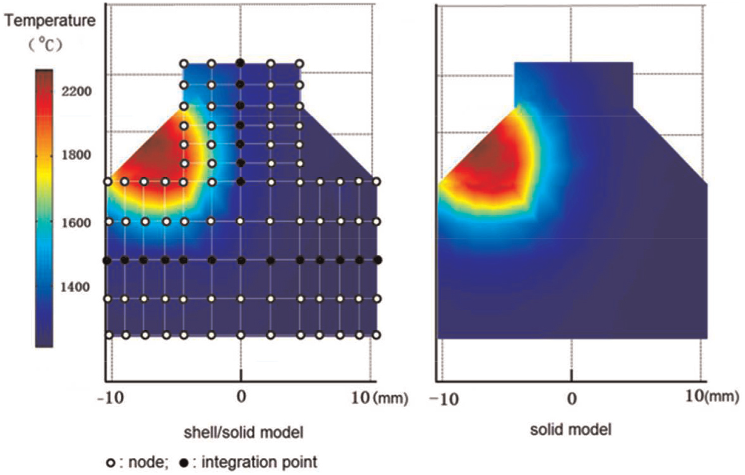
Temperature field.
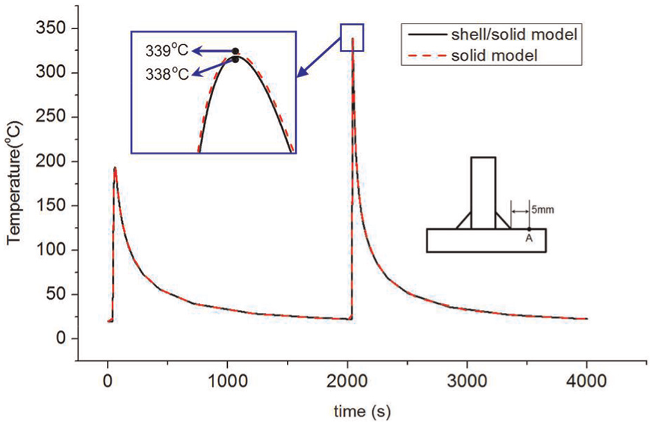
Temperature history.
The experimentally measured and simulation results of the out-of-plane distortions at three lines A-A, B-B and C-C are illustrated in Figure 11. The overall distortions of the fillet joint are shown in Figure 12. Reasonably good agreements in deformations are obtained by shell/solid model. The longitudinal stresses S22 along welding line at line B-B are illustrated in Figure 13. Similar agreements are obtained too. From these results, we can conclude that the proposed method can predict welding deformation and stress of tee joints effectively.
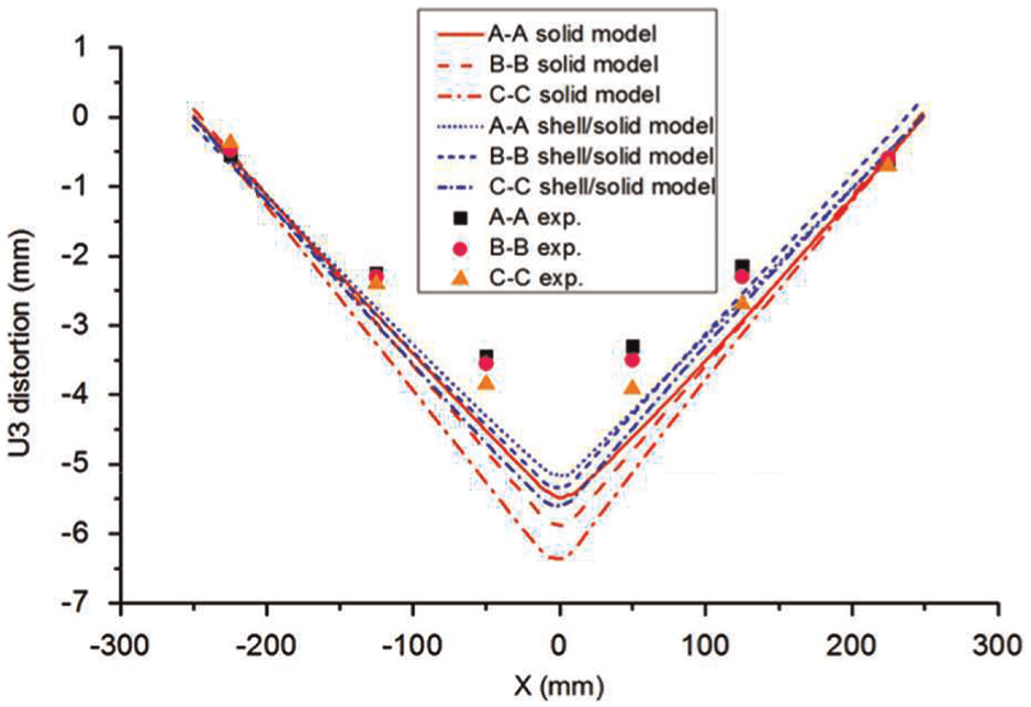
Out-of-plane distortions.
Welding distortion: (a) solid model and (b) shell/solid model.
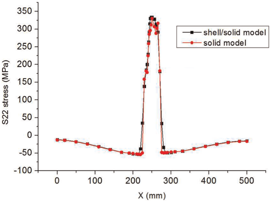
Mid-surface longitudinal stress.
The distortion under various welding procedures
The welding distortions of the structure under various procedures are presented in this section. Figure 14 shows the final overall and local deformation contours of WS1 and WS2. Hogging bending of stiffeners along the longitudinal direction is exhibited in all welding cases, which is the primary feature of overall distortion of the structure. Local distortions occur between two adjacent stiffeners.
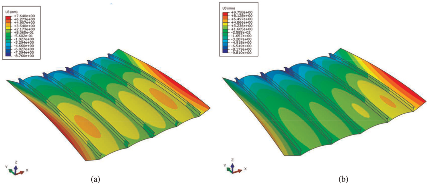
Deformation contours: (a) WS1 and (b) WS2.
Figure 15 illustrates the vertical distortion at Line 1 under the three welding cases. The significant difference between the three welding cases lies in the overall torsion of structure. Corresponding to the boundary condition, the vertical distance of two ends of stiffeners S4 and S5 at Line 1 position indicates the torsional extent of the structure. WS1 has a smallest overall torsional distortion compared to the other two cases of successive and bidirectional welding. It is seen that simultaneous welding of fillet joints in the structure generates less overall distortion of structure.
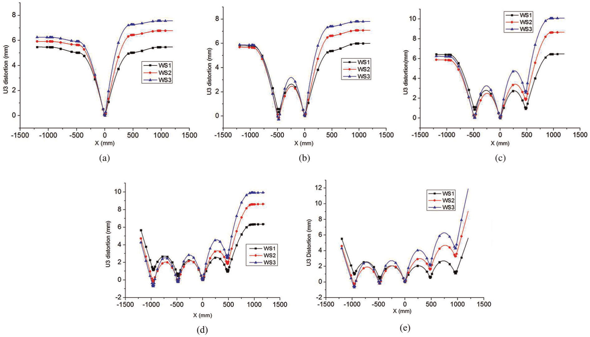
Vertical distortion at Line 1: (a) after first stiffener, (b) after second stiffener, (c) after third stiffener, (d) after fourth stiffener and (e) after fifth stiffener.
Overall torsional distortions under WS2 and WS3 are attributed to the asymmetric distortion of fillet joints of the structure. For the welding case of WS1, the structure distortion after cooling down of the first stiffener S1 weld is quite symmetric (Figure 15(a)) and the symmetry keeps well when all stiffeners are welded. Considering the welding case of WS2 and WS3, it can be seen that asymmetric structural distortion takes place from the first stiffener being welded due to non-simultaneous heat input. The asymmetry develops more after next stiffener is welded, which evolves into the final overall torsion distortion of the structure. Comparatively speaking, the magnitude of overall torsion under WS3 is greater than that under WS2.
Possible improvement of welding procedure
The overall torsional distortion of structures is particularly troublesome because it is hard to mitigate against when it couples with global bending and local distortion. Wang et al. 21 studied the twisting distortion of a thin plate stiffened structure and found that the twisting distortion can be produced by inappropriate welding processes. In this section, an exploration of possible improvements in the welding procedure is reported. This is done by adjusting the welding procedures of some fillet joints in the structure to ameliorate the torsional distortion features of the structure. Figure 16 shows the difference of welding procedure between the improved welding case of WS4 and WS2. The sequence of stiffeners being attached to plate in WS4 is same as WS1, WS2 and WS3. In the WS2 welding case, two weld passes of fillet joints of all stiffeners are implemented first on the left side and then on the right side. In WS4, the two weld passes of fillet joints of stiffener S2, S4 and S5 are reversed, namely first the right side and then the left side.
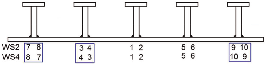
Improved welding procedure.
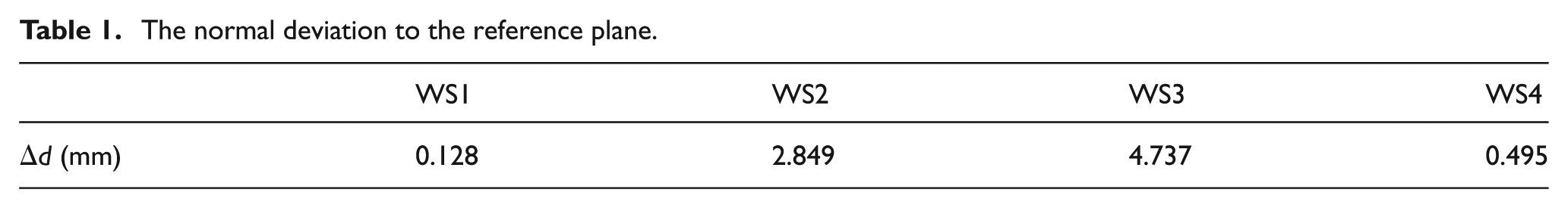
Compared with the welding case of WS2, good distortion symmetry to middle stiffener S1 under WS4 can be observed from Figure 17, which demonstrates a good improvement of overall torsional distortion through adjusting welding procedure. In order to quantify the magnitude of distortion, a reference plane defined on the deformed structure is introduced here (Figure 18). Three points of A, B and D at the ends of stiffener S4 and S5 are chosen to form the plane. The normal distances Δd from point D to the reference plane at four welding cases are calculated and listed in Table 1. After adjusting the welding sequences of some fillet joints, the distance Δd decreases from 2.849 mm under WS2 to 0.495 mm under WS4. A small deviation demonstrates a little torsion existed in the structure. For stiffened panels, welding sequences and procedures may generate non-uniform local distortion of stiffener panels, which can be used to improve overall distortion behavior of them.
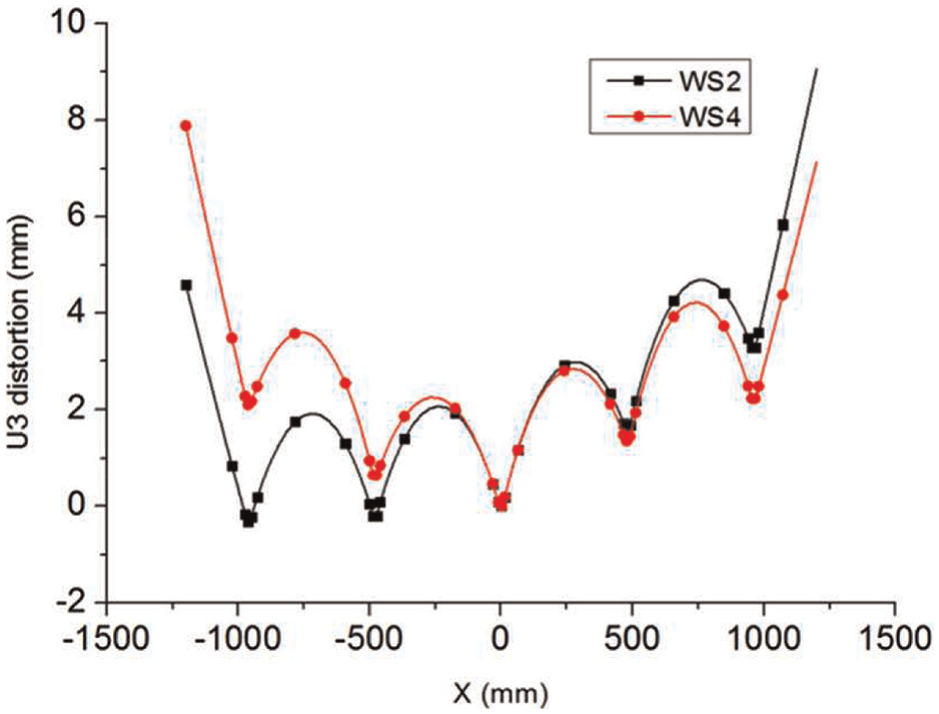
Vertical distortion under WS2 and WS4.
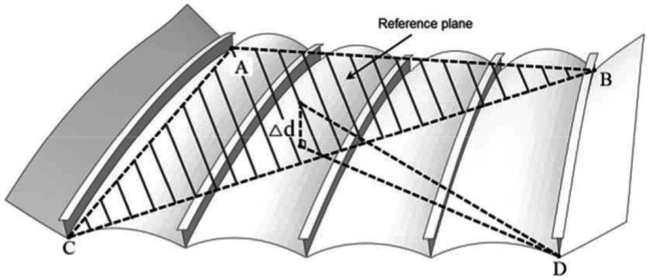
The reference plane.
The normal deviation to the reference plane.
Residual stress
The residual stress distributions of the longitudinal mid-surface stress S22 under the welding cases of WS1 and WS4 are shown in Figure 19. The tensile stresses are located at the plate edges between two stiffeners and the narrow band region near welding lines. The width of the tensile stress band is about 80 and 60 mm for WS1 and WS4, respectively. The compression residual stress more than 80 MPa occupies most area of the plate under WS1, while the corresponding areas under WS4 are only concentrated in the ends of stiffeners. The difference can be explained that the mirror effect of heat conduction is significant in simultaneous welding and the heat energy inputted from weld torch is harder to conduct to neighbor materials compared with successive welding. Consequently, more thermal energy is absorbed in simultaneous welding condition to expand parent materials, which produces larger range of tensile stress than that in successive welding.
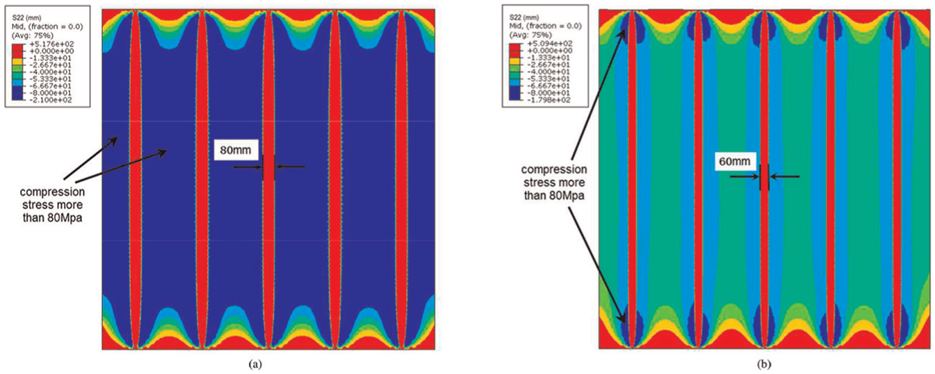
Residual stress contours: (a) WS1 and (b) WS2.
The welding distortion and compressive residual stress in a thin plated panel structure under different fabrication procedures were studied by Deng and Murakawa. 2 Two fabrication procedures were compared and discussed in the study. The first, Case C, was a single-sided welding. The longitudinal and transverse stiffeners of the structure were welded at the same time. In the second, Case D, the longitudinal stiffeners and transverse stiffeners were fabricated and welded successively. After each fabrication procedure, the gaps between stiffeners and skin plate were corrected. The fabrication included five welding and gap correction steps totally. The results here focus on the differences in the residual stress in the stiffened panel under various welding procedures. Figure 20 shows the residual stress S22 of the plate at the middle transverse section of the panel. The compressive stress between two adjacent stiffeners under WS1 reaches 85 MPa, which is larger than that of 50 MPa under WS1, WS2 and WS3. The welding procedures of WS1, WS2 and WS3 induce similar magnitude of residual stress in the structure. It should be noted that the greater compression residual stress in panel is, the easier buckling distortion of the panel takes place. Both fabrication and welding procedure influence the distortion and residual stress of welded structures.
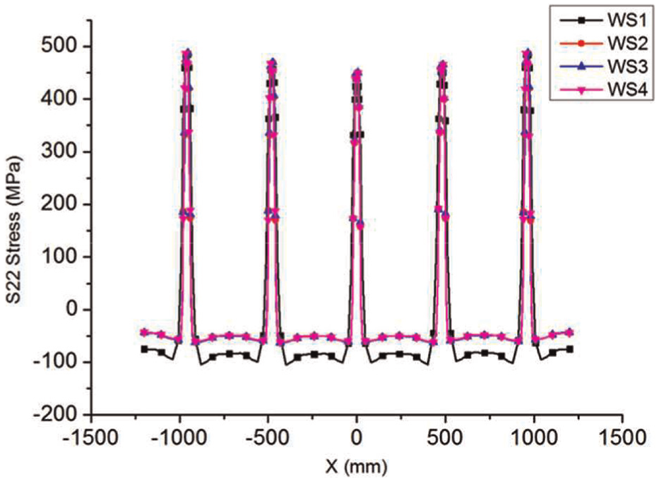
Residual stress at transverse section of plate.
Conclusion
This article carries out the comparative study of welding procedure of a stiffened panel. The welding process of the structure is simulated through a thermal elasto-plastic FEM using SESI. Welding distortion and residual stress in structure under simultaneous, successive and bidirectional welding are studied. The conclusions are summarized in the following.
The influences of welding procedure on welding distortion and residual stress in the stiffened panel are significant even under same weld heat input. Simultaneous welding induces less overall torsion distortion of the structure compared with successive and bidirectional welding. It is feasible and practical to improve overall torsion distortion of stiffened structures by adjusting welding procedure. Greater residual stresses are induced in the structure by simultaneous welding, which makes plating more easily buckle. The numerical approach used in this article can serve as an effective tool for improving welding procedures of stiffened panels. The experimental validation and comparison with simulation results for welding distortion and residual stress is left for future works.
Footnotes
Declaration of conflicting interests
The author(s) declared no potential conflicts of interest with respect to the research, authorship and/or publication of this article.
Funding
The author(s) received no financial support for the research, authorship and/or publication of this article.