
Abstract
This article covers the efforts on characterising ice-bonded abrasive polishing tool in terms of the mechanical and tribological properties such as hardness, coefficient of friction, and wear rate. These studies were attempted on the tools prepared at different temperatures ranging from −10 °C to 0 °C with a view to identify the condition suitable to prepare ice-bonded abrasive polishing tool for effective polishing of Ti–6Al–4V alloy specimen. It also presents the methods adopted to determine various properties of ice-bonded abrasive polishing tool. Hardness was estimated from the measured penetration depth of cone shape indenter into the tool, coefficient of friction was determined from the change in power drawn by the motor rotating the tool mould, and wear behaviour of tool was assessed from the melting rate of the tool determined from the change in height of ice-bonded abrasive polishing tool at different stages of polishing. From the results of this study, it is clear that ice-bonded abrasive polishing tool prepared at −4 °C has possessed sufficient hardness, coefficient of friction, and reasonable wear rate suitable for polishing of Ti–6Al–4V specimens. This article also covers the details of low-temperature coolant supply unit developed to prepare the ice-bonded abrasive polishing tool at any desired temperature between 0 °C and −40 °C and thus to maintain it for a long time. Polishing studies with such ice-bonded abrasive polishing tool showed 72% improvement in finish after 90 min of polishing of Ti–6Al–4V specimen with tool, prepared at −4 °C.
Introduction
Ultrafine surface generation processes such as lapping and polishing are assuming greater significance in view of the need for nano-level finish on various components used in precision systems such as optical, semiconductor, and medical devices.1–3 In polishing, fine abrasives remove micro asperities left out on the components by previous manufacturing processes and generate ultrafine finish on the work surfaces. These abrasives are used in a variety of forms such as bonded abrasives in grinding and loose abrasives in lapping and polishing. In bonded abrasive tools, the bonding material provides sufficient strength to abrasive grains during grinding. These tools must possess sufficient hardness, wear resistance, and the ability to withstand forces and temperatures during grinding.4–6 Generally, bonded abrasive tools are periodically sharpened by means of dressing which interrupts production. Finishing with bonded abrasive tools leaves out certain scratches on the components and thus limits their use for ultrafine finishing. In polishing with loose abrasives, the abrasives held loosely in a fluid, that is, a slurry of abrasives, are employed in various processes such as lapping, chemical mechanical polishing (CMP), magnetic assisted polishing, fluidised abrasive polishing, and water jet polishing. In all these processes, sedimentation and agglomeration of loose abrasives are avoided by maintaining the properties of suspension and by precisely feeding the suspension into the polishing zone.7–9 Consistent results are realised by periodically conditioning the polishing pads used in many polishing methods.10,11 Some of the drawbacks associated with bonded and loose abrasive finishing methods are overcome by unconventional methods of polishing such as liquid-bonded wheel, frozen magnetic fluid grinding wheel, magnetic-bonded abrasive particles, soft abrasive grinding wheel (SAGW), and sol–gel polishing pads.12–15 Recent attempt covers the development of a frozen abrasive tool that can possess the characteristics of bonded and loose abrasive tools and can continuously expose fresh abrasive particles by melting of frozen tool, that is, self-dressing capability, during polishing. In this method, a frozen mixture of de-ionized water and very fine particles of cerium oxide (CeO2) and aluminium oxide (Al2O3) is combined with polymer-type surfactant for polishing of silicon wafers. The temperature of the tool was maintained below 0 °C by supplying cold air. 16 An attempt was made for in situ preparation of polishing tool, known as ice-bonded abrasive polishing (IBAP) tool, by freezing the suspension of water and silicon carbide (SiC) particles with liquid nitrogen. As this method of freezing the suspension could not maintain the tool at any particular temperature for a long period during polishing, the polishing tool could be used only for about 15 min.17–19 The set-up for making the IBAP tool was modified with a separate refrigeration unit that could continuously circulate a mixture of ethylene glycol and water, that is, coolant, through a heat exchanger of refrigeration unit. With this set-up, the temperature of the coolant could be brought down to −12 °C from ambient temperature. Although this method took about 5–6 h for preparing a tool of 200 mm diameter with 30 mm height, this tool could be used for polishing of specimen only for 30 min. Furthermore, the temperature of polishing tool could not be maintained at any desired temperature due to manual method of control of refrigeration unit. 20 To enhance the life and performance of IBAP tool for polishing of metallic specimens, this work attempts to develop a low-temperature coolant supply unit for preparation of IBAP tool and then characterises the IBAP tool in terms of the mechanical and tribological properties such as hardness, coefficient of friction, wear resistance, and self-dressing ability.
Background
The thermo-mechanical properties of ice such as thermal conductivity, density, elastic modulus, hardness, and coefficient of friction depend on the temperature of ice. In the past, a few attempts were made to study the variation in elastic modulus, strength, hardness, and coefficient of friction of ice maintained at different temperatures. The elastic modulus of polycrystalline ice was found to vary from 0.3 to 12 GPa when the temperature of ice was maintained in the range of −0.1 °C to −10 °C.21–24 In fact, the elastic modulus of ice prepared at lower temperatures was found to be high and the ice has behaved like a perfect elastic body obeying Hooke’s law. 21 The compressive strength of ice has also increased with reducing temperatures and is found to increase from 4.9 MPa at −0.1 °C to 15 MPa at −10 °C. In contrast to this, the tensile strength of ice is found to lie between 1.7 and 2.4 MPa with the temperature of ice maintained between −0.1 °C and −10 °C.22,23,25 Similarly, the compressive strength of frozen silty clay maintained at temperatures of 0 °C and −10 °C is found to be higher than that of pure ice.26,27 The hardness of ice maintained at different temperatures between 0 °C and −50 °C is also found to increase with reducing temperatures.28–30 In fact, the hardness of polycrystalline ice was found to vary from 6 to 20 MPa when the temperature of ice was maintained in the range of 0 °C to −10 °C. At higher temperatures, the hardness of ice has reduced due to the formation of liquid-like state of ice at grain boundaries. 29 The ice maintained at temperatures below −40 °C is found to have a very high coefficient of friction since the formation of water film over the ice at this temperature is more difficult and the interaction of the material with ice is mostly solid–solid interaction. The ice maintained at temperatures between −9 °C and −6 °C has less coefficient of friction but increased when its temperature reached 0 °C.31–34 The coefficient of friction between ice and ultra-high-molecular-weight polyethylene (UHMWPE) ski sole was found to decrease with increasing temperature. Above 0 °C, the ice became very soft and the coefficient of friction has decreased. During ski sliding on ice surface whose temperature is −5 °C, the ski sole has worn out and became flat due to rubbing of sole surface with hard ice particles. 35 All these studies have clearly stressed the relevance of ice temperature to realise the desirable coefficient of friction between the ice surface and any interacting surface with it.
From the above, it is clear that the mechanical and tribological properties of ice are likely to vary with the temperatures chosen for preparing IBAP tool and can, in turn, influence its performance during polishing. In general, the bonding material (ice) must have sufficient hardness and wear resistance, to retain the abrasives and enhance the life of bonded abrasive tool.4,5 But the friction between the work surface and the polishing pad surface plays an important role in material removal rate and surface finish during polishing process.36,37 Hence, this work is envisaged to study the variation in the properties of IBAP tools prepared at different temperatures and then to identify a window of temperatures suitable for preparing IBAP tool for fine finishing applications.
The studies cover characterisation of IBAP tool in terms of hardness, coefficient of friction, and wear rate of IBAP tool prepared at different temperatures ranging from −10 °C to 0 °C. This article also covers the procedures employed for measuring hardness, coefficient of friction, and the rate of melting of IBAP tool along with the details of low-temperature coolant supply unit developed to maintain IBAP tool at any chosen temperature for a long duration. Finally, the effect of IBAP tool properties on polishing performance of IBAP tool was assessed by a set of polishing experiments conducted over flat Ti–6Al–4V alloy samples with IBAP tool.
Experimental set-up
IBAP set-up
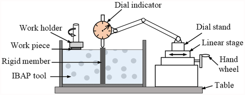
Figure 1(a) shows a schematic diagram of IBAP set-up. It consists of low-temperature coolant supply unit, workpiece handling unit, polishing tool holding unit, and temperature measuring unit.
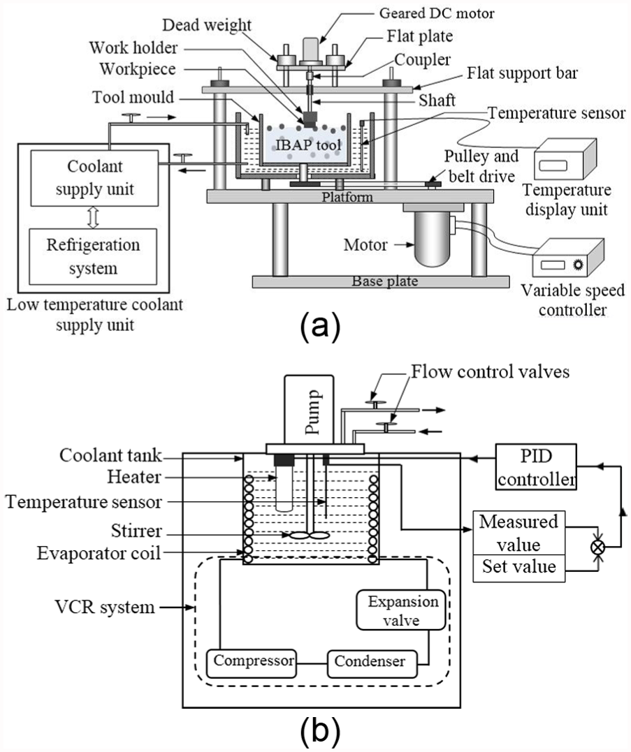
(a) Schematic diagram of ice-bonded abrasive polishing set-up and (b) low-temperature coolant supply unit.
Figure 1(b) shows the detailed schematic diagram of low-temperature coolant supply unit. It was developed to supply the coolant, at low temperatures in the range of 0 °C to −40 °C, around the tool mould to freeze the slurry into IBAP tool. This unit has a vapour compression refrigeration (VCR) system for removing the heat from the coolant. This particular system was chosen since it has a high coefficient of performance (COP). In this system, R404a was used as the refrigerant since its boiling point is at about −46 °C. As this refrigerant poses global warming problems when exposed to open atmosphere, this refrigerant was used to cool isopropyl alcohol, whose freezing temperature is at about −86 °C. The temperature of the coolant was maintained at any set temperature with the help of a proportional–integral–derivative (PID) controller that collects the temperature measured by a resistance-type temperature sensor (PT 100), having a range of −150 °C to 850 °C. The controller takes the measured temperature and compares it with the set temperature to either switch on or off a heater (Figure 1(b)). In this scheme, when the temperature of the coolant falls below the set temperature, the heater will be switched on to raise the temperature of the coolant and thus maintains the coolant at any set temperature. By stirring the coolant continuously with a mechanical stirrer, the temperature of the coolant in the tank was maintained uniformly. With the help of coolant pump and ball valve, the coolant was circulated around the tool mould and its level around the mould was also maintained.
The workpiece handling unit consists of a work holder to hold the workpiece and direct current (DC) motor to drive the shaft of the work holder. The relative motion between the workpiece and the polishing tool was ensured by rotating the shaft at a desired speed using a variable speed controller. The workpiece was rigidly held in the work holder, which is connected to one end of the shaft. The other end of the shaft was driven by the geared DC motor. The entire assembly can be moved vertically over four guide rods fixed to a flat support bar. Uniform contact between the work surface and the tool surface was ensured by placing the dead weights on either side of the plate holding the motor, as shown in Figure 1(a).
The polishing tool holding unit essentially consists of a tool mould of 215 mm diameter with 85 mm height. A set of reinforcements are provided at the bottom of the mould to hold the IBAP tool in the mould. The outer mould surface was insulated by a thermal foam, and the heat transfer between the coolant and the environment was minimised. The IBAP tool of 200 mm diameter and 30 mm thickness was prepared using layer-by-layer freezing method, 17 and the time taken to prepare the tool was about an hour. The relative motion between the polishing tool in the mould and the workpiece was provided by driving the mould with a belt and pulley arrangement made with a permanent magnet DC motor. Its rotational speed was varied between 10 and 600 r/min with a variable speed controller.
The temperature measuring unit measures the temperature of the coolant circulated around the mould. To measure the temperature of the coolant, a resistance-type temperature sensor (PT 100), capable of measuring the temperature up to −150 °C, was placed in contact with the coolant around the tool mould. The resolution of measurement of the temperature is 0.1 °C.
Methodology
This section describes the procedure adopted for characterisation of IBAP tool prepared at different temperatures ranging between −10 °C and 0 °C.
Characterisation of IBAP tool
As the performance of IBAP tool depends on its thermo-mechanical properties, this study was attempted to characterise IBAP tool in terms of hardness, coefficient of friction, and tool wear. The procedures followed to determine these properties of tool, prepared at any temperature in the range of −10 °C to 0 °C, are outlined here.
Estimation of hardness
As the hardness of ice influences its retention strength of abrasives in IBAP tool, this particular study was taken up to measure the indentation hardness of the composite IBAP tool. Figure 2(a) shows the set-up employed for determining the indentation hardness of IBAP tool with a cone-type penetrometer. Figure 2(b) shows the shape of stainless steel cone indenter, having a cone angle of 30 °. The weight of cone assembly is 80 g. Enough care was taken to ensure the axis of indenter perpendicular to the surface of IBAP tool. A cone-shaped indenter was allowed to fall freely on IBAP tool by manually releasing the button and allowing the indenter to stay on the tool surface for a period of 5 s. Its depth of penetration into the tool was measured from the dial indicator. 38 The same procedure was repeated to measure the depth of penetration at three different locations of 30, 50, and 70 mm from the centre of IBAP tool in the radial direction, as shown in Figure 2(c). The average of three readings was considered as the depth of penetration (h) and the same was used to estimate the indentation area. The indentation hardness (H) of IBAP tool was estimated by means of the following relationship between the indentation area (Ai) of a cone indenter and the load (W)
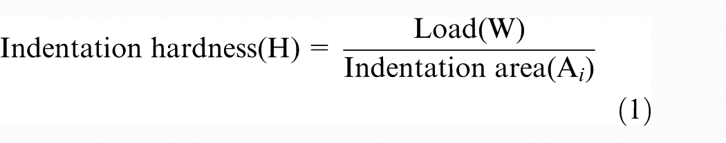
(a) Photograph of cone penetrometer set-up, (b) cone indenter, and (c) location of hardness measurement on IBAP tool.
The peripheral surface area of the cone is considered as the indentation area of the cone and can be estimated with the expression


where h is the depth of penetration, and r is the radius of cone at corresponding ‘h’.
Estimation of coefficient of friction
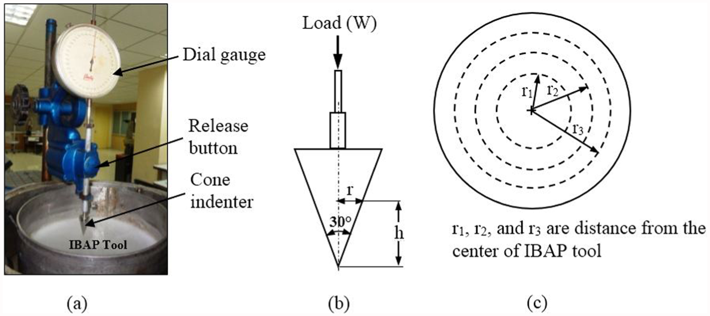
As the friction between the work surface and the polishing pad plays an important role in material removal rate, degree of surface finish, and pad wear during the polishing process, this study was aimed to determine the coefficient of friction between the IBAP tool surface and the Ti–6Al–4V alloy surface. There are several methods to determine the coefficient of friction by measuring friction forces using load cell, piezoelectric sensor, tool dynamometer, and non-contact capacitive displacement sensor.39–43 It is also possible to determine the coefficient of friction between the work and the tool surface by monitoring the variation in the current drawn by the motor driving the tool during polishing of the work surface. 44 As this method is much easier compared to other methods, this work considered the measurement of power drawn by the motor rotating the tool mould. Figure 3 shows the illustration of power measurement scheme to measure the power drawn by the motor. The power cell was directly connected to the input power line of motor, and its output was collected by a data acquisition (DAQ) unit. The power cell is a Hall-effect sensor that measures the current and samples the voltage simultaneously. Analogue current signals are discretized with analogue-to-digital converter (ADC) and the same are stored in the computer for further processing. With a vector multiplication of measured current and voltage with the power factor, the system measures the actual power drawn by the motor.
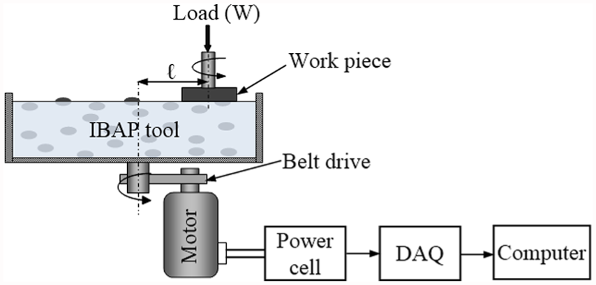
Illustration of power measurement scheme.
The experiments were performed with IBAP tool, made of silicon carbide abrasives of 2 µm size and 5% concentration at different temperatures chosen from the range of −10 °C to −0 °C. The Ti–6Al–4V specimens were polished for a period of 1200 s with IBAP tool, rotating at 150 r/min, load of 30 N, and the distance between the centre of IBAP tool and the centre of the work surface is 65 mm. To determine the change in coefficient of friction at different stages, the power drawn by the motor before the work surface is engaged with the IBAP tool surface is measured and is termed as idle power (Pi). During the initial stage of engagement of the work surface with the IBAP tool surface, the power drawn by the motor (Ps) was measured. Similarly, the power drawn by the motor (Pp) during polishing was also collected. As the frictional resistance between the work surface and the IBAP tool surface changes at different stages of interaction of the work surface with the tool surface, the variation in power was used to determine the change in coefficient of friction (µ) at different stages of polishing.
As the power drawn by the motor varies with the friction between the work surface and the tool surface, the change in the power (ΔP) drawn by the motor was used to determine the frictional torque (Tf)

where ΔP is the difference between the power drawn at different stages of polishing (Pp) and the idle power (Pi), and N is the rotational speed of IBAP tool.
The frictional torque (Tf) can also be determined by knowing the frictional force (Ff) between the work surface and the IBAP tool surface and the distance (l) between the centre of IBAP tool and the centre of the work surface

The frictional force (Ff) can be related to the load (W) applied on IBAP tool and the coefficient of friction (µ) between the interacting surfaces

From the above set of equations, the coefficient of friction (µ) can be estimated

Estimation of wear rate
As the life of IBAP tool can be assessed from the rate of wear and the magnitude of wear on IBAP tool, this particular study was attempted to measure the rate as well as the magnitude of wear on IBAP tool. Figure 4 shows the schematic diagram of set-up employed for measuring the wear on IBAP tool. In this set-up, a rigid block was placed at the centre of tool mould and is used as a reference surface. A dial gauge with its stand was mounted on a linear translation stage and the entire unit was placed on the table. The tip of the dial gauge was made to touch the reference surface first and then different points on this tool. 45 A dial gauge, having a resolution of 0.01 mm, was used to measure the change in the height of IBAP tool. A disc-shaped Ti–6Al–4V specimen was polished with IBAP tool for a certain duration, and the change in the height of the tool measured with the dial gauge was used to estimate the average wear. The same procedure was repeated on the tool after every 20 min of polishing for a total duration of 120 min. Each test was performed twice, and the average of these readings was taken as the wear on IBAP tool, prepared at a particular temperature.
Schematic diagram of tool wear measurement set-up.
With these methods of characterisation of IBAP tool, it is possible to obtain the ranges of hardness, coefficient of friction, and wear on IBAP tool prepared at any temperature in the range of −10 °C to 0 °C. With this knowledge of the properties of IBAP tool and the relationship between the properties of tool and its performance in polishing of materials, it is possible to select suitable temperatures for preparing IBAP tool for longer tool life and better performance in polishing of the materials.
Relationship between the properties and polishing performance of IBAP tool
To understand the effect of the tool properties on its performance in polishing, a set of polishing experiments were performed with IBAP tool, made of silicon carbide abrasives of 15 µm size and 5% concentration at different temperatures chosen from the range of −10 °C to −0 °C. An improvement of finish on the polished surface was used as the criterion for assessing the performance of IBAP tool. From this study, the range of temperatures that are effective to prepare the tool is established. Detailed polishing experiments were conducted with IBAP tool prepared with the temperatures chosen from this range. This study was aimed at investigating the performance of IBAP tool over different durations of polishing and to identify the exact temperature of the tool that can quickly polish the surface. All polishing experiments were conducted on Ti–6Al–4V alloy circular disc of 22 mm diameter with 15 mm thickness. The surface was first machined on a computer numerical control (CNC) lathe and is ground on a surface grinding machine using Al2O3 wheel. The ground surface was further polished with hand polishing using 220, 400, 600, 800, and 1000 grades of SiC metallographic emery sheets. Hand polished surfaces were cleaned with pressurised water and then dried with air. The Ti–6Al–4V specimens were polished for a period of 120 min with IBAP tool, rotating at 150 r/min, and polishing pressure of 79 kPa. The finish on the work surface before and after polishing with IBAP tool was measured by a non-contact, high-resolution three-dimensional surface measuring instrument, optical surface profiler.
Results and discussion
Characterisation of IBAP tool
Variation in IBAP tool hardness with temperature
As explained earlier, the hardness of IBAP tool was estimated from the measurement of the depth of indentation of cone-shaped indenter into the tool surface. Figure 5(a) shows the variation in hardness of pure ice and the IBAP tool, prepared at different temperatures. From these trends, it is clear that the hardness of ice and IBAP tool decreased with increasing temperatures. In any case, the variation in hardness of ice with temperature is in close agreement with the data reported.28–30 In fact, the hardness of IBAP tool prepared at −10 °C and −8 °C is higher compared to the hardness of the tool prepared at other temperatures. The hardness of IBAP tool prepared above −6 °C is observed to be the least which can be attributed to the formation of liquid film at the grain boundaries due to melting of ice.29,30 In Figure 5(b), the variation in hardness of IBAP tool prepared with different concentrations of abrasives is presented. From these results, it can be noticed that the hardness of IBAP tool has increased with increasing concentration of abrasives only with the tool prepared at temperatures of −10 °C and −8 °C. In contrast to this, the hardness of IBAP tool, prepared at temperatures between −6 °C and 0 °C, did not vary much even with increasing concentration of abrasives. This can again be attributed to the formation of liquid at grain boundaries due to the melting of ice with applied pressure. Figure 5(c) shows the variation in hardness of the tool in different regions along the radial direction. From the results, it is clear that the hardness of IBAP tool is almost the same in different regions of the IBAP tool surface when the tool was prepared at any particular temperature ranging from −6 °C to 0 °C. Contrary to this, the hardness of IBAP tool has increased with increasing distance from the centre of IBAP tool when the tool was prepared at temperatures of −10 °C and −8 °C. It can be attributed to an immediate cooling of this region being close to the coolant.
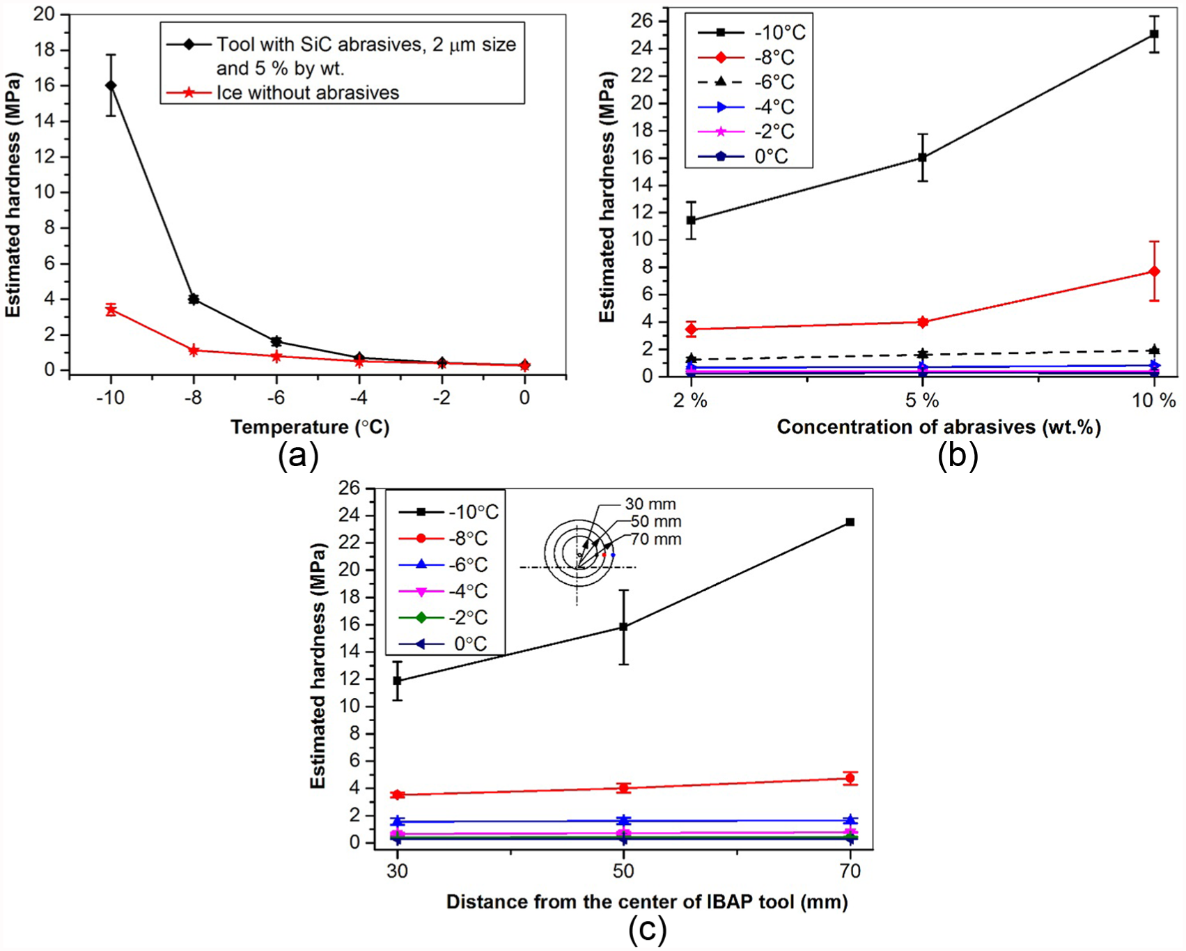
Variation in IBAP tool hardness (a) with temperature, (b) with concentration of abrasives, and (c) in radial direction.
From the results presented in Figure 5, it is clear that the hardness of IBAP tool has increased with reducing temperature chosen for preparation of the tool, increasing concentration of abrasives, and increasing distance from the centre of the tool prepared at temperatures of −10 °C and −8 °C. On the other hand, the IBAP tool, prepared at temperatures above −6 °C, has almost uniform hardness even with increasing concentration of abrasives and distance from the centre of the tool. Thus, this study clearly indicated the possibility of producing a harder tool with temperatures of −10 °C and −8 °C, medium hardness tool with temperatures of −6 °C and −4 °C, and softer tool with temperatures of −2°C and 0 °C. Since the hardness of IBAP tool influences its retention strength of abrasives, it is important to make the IBAP tool with suitable hardness for retaining the abrasive grains on the tool surface for a longer duration during polishing.
Variation in coefficient of friction between IBAP tool and work surface
As explained earlier, the coefficient of friction between the IBAP tool surface and the work surface can be determined from the measurement of power drawn by the motor driving the tool mould. Figure 6 shows the variation in power drawn by the motor with time while IBAP tool, prepared at different temperatures ranging between −10 °C and 0 °C, was involved in polishing. From the trends presented in Figure 6(a), it can be observed that the average power drawn by the motor is about 85 W before the work surface made a contact with the IBAP tool surface, that is, idle power (Pi). As soon as the work surface made a contact with the tool, prepared at a temperature of −10 °C, the average power drawn by the motor has shot up to about 110 W and has remained more or less the same during the interaction of the work surface with the tool surface for a period of 700 s. But the power drawn by the motor has dropped slowly to 100 W beyond 700 s. It can be attributed to the solid–solid interaction of the tool and the work initially, but beyond 700 s of interaction, a very thin layer of ice formed over the tool reduced the interfacial friction. Figure 6(b) and (c) shows the variation in power with the duration of interaction of the work over the tool, prepared at temperatures of −8 °C and −6 °C. Although the variation in power during the initial period remained the same, the power drawn by the motor has abruptly increased to 103 W at 120 s and remained at the same level throughout the period of interaction of the work with the tool, prepared at −8 °C. In a similar manner, the power drawn by the motor has suddenly increased to 101 W at 120 s and remained at the same level throughout the period of interaction of the work with the tool, prepared at −6 °C.
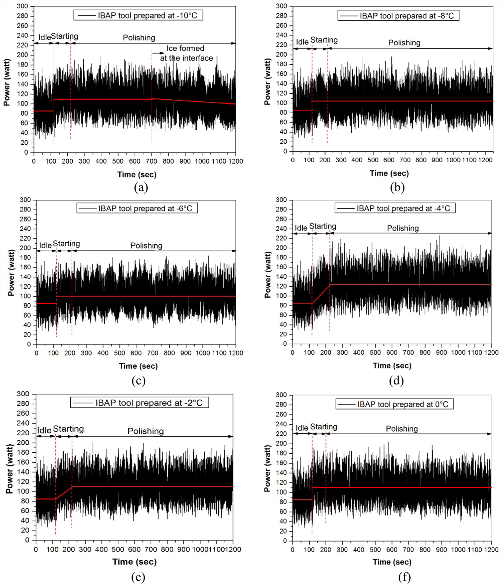
Variation in power drawn by the motor at different stages of polishing (a) at −10 °C, (b) at −8 °C, (c) at −6 °C, (d) at −4 °C, (e) at −2 °C, and (f) at 0 °C.
Figure 6(d) shows the variation in power drawn by the motor when the work has interacted with a tool, prepared at −4 °C. Although a similar trend of variation in power was noticed till 120 s, the power has slowly increased to 120 W beyond 120 s and remained the same for a long duration. Such a gradual increase in power can be attributed to the formation of a thick film of water between the IBAP tool and the work surface which offered more resistance to sliding thus increasing the power slowly. After this film has reached a steady state, the power drawn by the motor remained the same, as can be seen from Figure 6(d). Figure 6(e) and (f) shows the variation in power with the duration of interaction of the work over the tool, prepared at temperatures of −2 °C and 0 °C. As observed earlier, the initial trends are the same till 120 s. But the power drawn by the motor has gradually increased to 110 W over the next 120 s and remained at the same level throughout the period of interaction of the work with the tool, prepared at −2 °C. In contrast to earlier observations, the power drawn by the motor has suddenly increased to 109 W at 120 s and can be attributed to a quick formation of water layer between the tool and the work surface. The same film could have continued throughout the period of interaction of the work over the tool prepared at 0 °C. At these temperatures, a thick layer of water was observed between the work surface and the IBAP tool surface which could increase the friction due to the need to overcome viscous shearing of water film34,46 and thus has resulted in an increase in the power drawn by the motor.
From the results presented in Figure 6(a)–(f), it can be concluded that the power drawn by the motor has reduced first with increasing temperatures chosen for preparing the tool and then increased when the tool was prepared at temperatures of −4 °C, −2 °C, and 0 °C. The power drawn by the motor is seen to be higher when the tool was prepared at a temperature of −4 °C. Increased coefficient of friction could be due to drag forces offered by the viscosity of slurry being high, at this temperature. 47 Therefore, the variation in power with the time of interaction of the work over the tool can be used to understand the change in friction between the IBAP tool surface and the work surface during polishing.
The estimated coefficient of friction between the IBAP tool surface and the work surface is 0.68, 0.58, 0.51, 0.94, 0.81, and 0.77 for IBAP tools prepared at temperatures of −10 °C, −8 °C, −6 °C, −4 °C, −2 °C, and 0 °C, respectively. In CMP, the coefficient of friction between silicon wafer and pads, having different hardness, was found to be 0.35–0.9 with colloidal silica abrasives. 48 Thus, the coefficient of friction values observed in this work are reasonable. From these results, it is clear that the coefficient of friction has decreased first with increasing temperature and then increased when the temperature chosen for the tool preparation has reached −4 °C. Thus, this study clearly indicated the least coefficient of friction between the tool and work surface when IBAP tool was prepared at temperatures of −8 °C and −6 °C. The same was also observed by Kietzig et al. (2010) during their studies on friction measurement of ice. But the coefficient of friction between the tool and the work surface is the highest when the tool was prepared at temperatures −4 °C and above. To confirm these trends, the wear on the tool, prepared at different temperatures ranging from −10 °C to −0 °C, was also measured.
Variation in IBAP tool wear with temperature
As described earlier, the wear resistance of IBAP tool is assessed by measuring the melting rate of the tool. Figure 7 shows the variation in wear on IBAP tool, prepared at different temperatures, ranging from −10 °C to −0 °C. From these results, it can be noticed that the wear on IBAP tool, prepared at a temperature of −10 °C, was insignificant. A similar trend can be observed with the tool prepared at a temperature of −8 °C. This can be attributed to very high hardness of the tool and low coefficient of friction between the tool and the work surface which has made the work surface to slide over the IBAP tool surface without causing any melting of the tool surface. The IBAP tool wear has increased slightly with increasing time of interaction of the work surface with the tool, prepared at a temperature of −6 °C. This can be attributed to medium hardness of the tool at this temperature. Similarly, the IBAP tool wear has increased gradually with increasing time of interaction of the work surface with the tool, prepared at −4 °C and −2 °C. At this temperature of −4 °C, the tool wear is seen to be reasonable, since the tool has possessed medium hardness with higher coefficient of friction. However, the wear of the tool prepared at −2 °C was much higher which could be due to lower hardness of the tool and higher coefficient of friction.
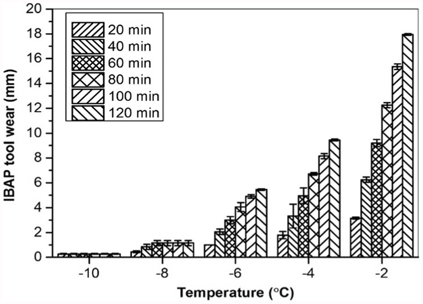
Variation in IBAP tool wear at different temperatures.
The IBAP tool wear rate is seen to be 0.014 mm/min and has reduced gradually with increasing time of interaction of the work surface with the tool, prepared at a temperature of −10 °C. Similarly, the tool wear rate has gradually reduced from 0.023 to 0.01 mm/min with increasing time of interaction of the work surface with the tool, prepared at −8 °C. With the tool prepared at temperatures of −6 °C and −4 °C, the tool wear rate is seen to be 0.05 and 0.09 mm/min, respectively, and is almost the same with increasing time of interaction of the work surface with the tool. The lower rate of tool wear is observed with the tool prepared at −6 °C compared to the tool prepared at −4 °C, having lower coefficient of friction. The higher rate of wear, that is, 0.158 mm/min, is observed on the tool prepared at −2 °C. Even the rate of wear is almost the same with increasing time of interaction of the work surface with the tool.
From these results, it can be concluded that the tool wear rate depends on the temperature of IBAP tool. The rate of wear on the tool, prepared at −2 °C, is much higher, but it is much lower on the tool prepared at −10 °C and is moderate on the tool prepared at −6 °C and −4 °C. When the tool is prepared at higher temperatures, the abrasive grains can easily be released from the bond material due to lower hardness and higher coefficient of friction between the tool and the work surface. Too high or too low wear rate of IBAP tool is not desirable since the life of the tool decreases due to rapid wear rate or less number of active abrasive grains available for polishing of the work surface.
Variation in hardness, coefficient of friction, and wear on IBAP tool
Figure 8 shows the variation in hardness, coefficient of friction, and wear on IBAP tool, prepared at different temperatures in the range of −10 °C to 0 °C. From these results, it is clear that the wear on the tool has increased when it is maintained at higher temperatures. This could be due to reduction in its hardness. In fact, the wear on IBAP tool, prepared at −10 °C, was negligible, since the tool possessed very high hardness at this temperature. However, the wear on IBAP tool, prepared at temperatures above −6 °C, has steadily increased, since the hardness of the tool was lower at this temperature. The tool wear became much higher over the tool prepared at 0 °C, since the tool possessed the lowest hardness at this temperature.
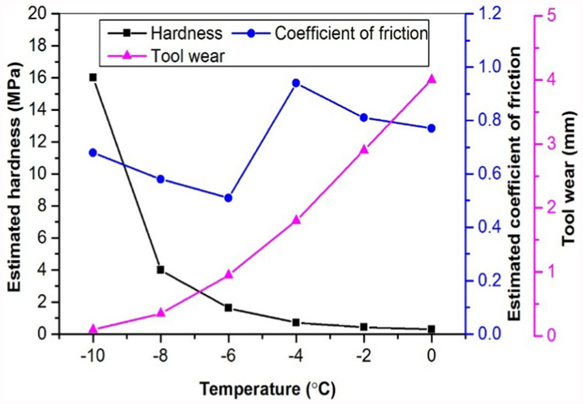
Variation in hardness, coefficient of friction, and tool wear on IBAP tool prepared at different temperatures.
The coefficient of friction has decreased from 0.68 to 0.51 when the temperature is increased from −10 °C to −6 °C, has further increased to 0.94 at −4 °C, and then reduced to 0.77 at 0 °C. This particular behaviour can be attributed to the formation of a thick layer of water film at about −4 °C which has offered more resistance to the relative motion of the work surface with the tool. This has resulted in an increase in power monitored with which the coefficient of friction was derived. However, this aspect needs further investigation.
From the characterisation of IBAP tool prepared at different temperatures of −10 °C to 0 °C, it is clear that the temperature of IBAP tool significantly influenced its mechanical and tribological properties. At the same time, this study has suggested the preparation of IBAP tool at a temperature of −4 °C, to have sufficient hardness, high coefficient of friction, and reasonable tool wear.
Relationship between the properties of IBAP tool and its polishing performance
As mentioned earlier, the influence of IBAP tool properties on its performance in polishing was assessed by measuring the finish on the polished surface. Figure 9 shows the variation in roughness on Ti–6Al–4V specimens polished with IBAP tool prepared at different temperatures ranging between −10 °C and −2 °C. From these results, it can be observed that the reduction in roughness, that is, improvement of finish on the specimen polished with the tool prepared at temperatures of −10 °C and −8 °C, is less when compared to that observed with the tool prepared at other temperatures. This can be due to higher hardness of the tool with low coefficient of friction which could not easily release the abrasives from the bonding material, thus hindering the polishing of the work surface. From the results, it can also be observed that the polishing tool is seen to be effective when it is prepared at temperatures of −6 °C, −4 °C, and −2 °C. With IBAP tool prepared at these temperatures, the finish (Ra) on the surface has improved to 0.081, 0.055, and 0.060 µm after 120 min of polishing. This amounts to 52.90%, 66.04%, and 64.45% of improvement in finish with IBAP tool. The tool prepared at temperatures −6 °C, −4 °C, and −2 °C exhibited higher percentage of improvement in finish than the tool prepared at other temperatures, since the tool possessed very less hardness and higher coefficient of friction between the work surface and the tool at these temperatures which could easily release the abrasive grains from the bonding material, thereby enhancing the number of active abrasive grains participating in polishing of the work surface. From the above results, it is confirmed that the variation in surface roughness on Ti–6Al–4V specimens polished with IBAP tools prepared at different temperatures ranging between −10 °C and −2 °C is due to variation in tool hardness and coefficient of friction between the tool surface and the work surface. However, the life of IBAP tool was quite low with the tool prepared at −2 °C and above. Therefore, this study suggests that IBAP tool is more effective when it is prepared at −6 °C and −4 °C.
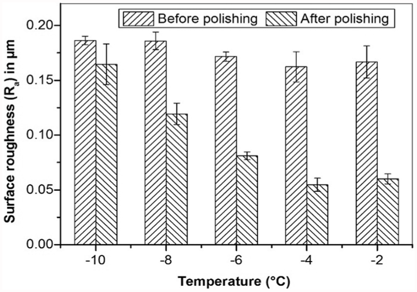
Effect of IBAP tool temperature on surface roughness (Ra).
As the coefficient of friction between the tool and the work surface is less at −6 °C compared to that observed at −4 °C, the polishing rate of IBAP tool was examined with the tool prepared at −6 °C and −4 °C to identify the exact temperature at which the tool can be prepared for quicker polishing of the surfaces.
Figure 10 shows the variation in three-dimensional surface topography on the specimen polished with IBAP tools prepared at −6 °C and −4 °C. From the results presented in Figure 10(a)–(d), it is evident that several peaks and valleys over the initial work surface are progressively removed upon polishing with IBAP tool prepared at −6 °C. But beyond 90 min, that is, after 120 min of polishing, the finish on the polished surface, as shown in Figure 10(e), has deteriorated and the average roughness (Ra) value has increased from 0.088 to 0.128 µm. Furthermore, the topography showed more number of peaks and valleys over the polished surface. The reason for this peculiar behaviour of IBAP tool prepared at −6 °C is due to worn out, and certain fresh abrasives held by ice matrix continue to interact with the already polished surface thus deteriorating the finish beyond 90 min of polishing. A closer observation of surface topography changes with polishing time (Figure 10(f)–(h)) discloses the faster removal of several peaks and valleys on the initial work surface within the polishing duration of 60 min with IBAP tool prepared at −4 °C. The average roughness (Ra) on the work surface has reduced from 0.271 to 0.078 µm within 90 min of polishing. The lower value of Ra with IBAP tool prepared at −4 °C can be attributed to the soft nature of the tool with lower hardness over that observed on IBAP tool prepared at −6 °C.
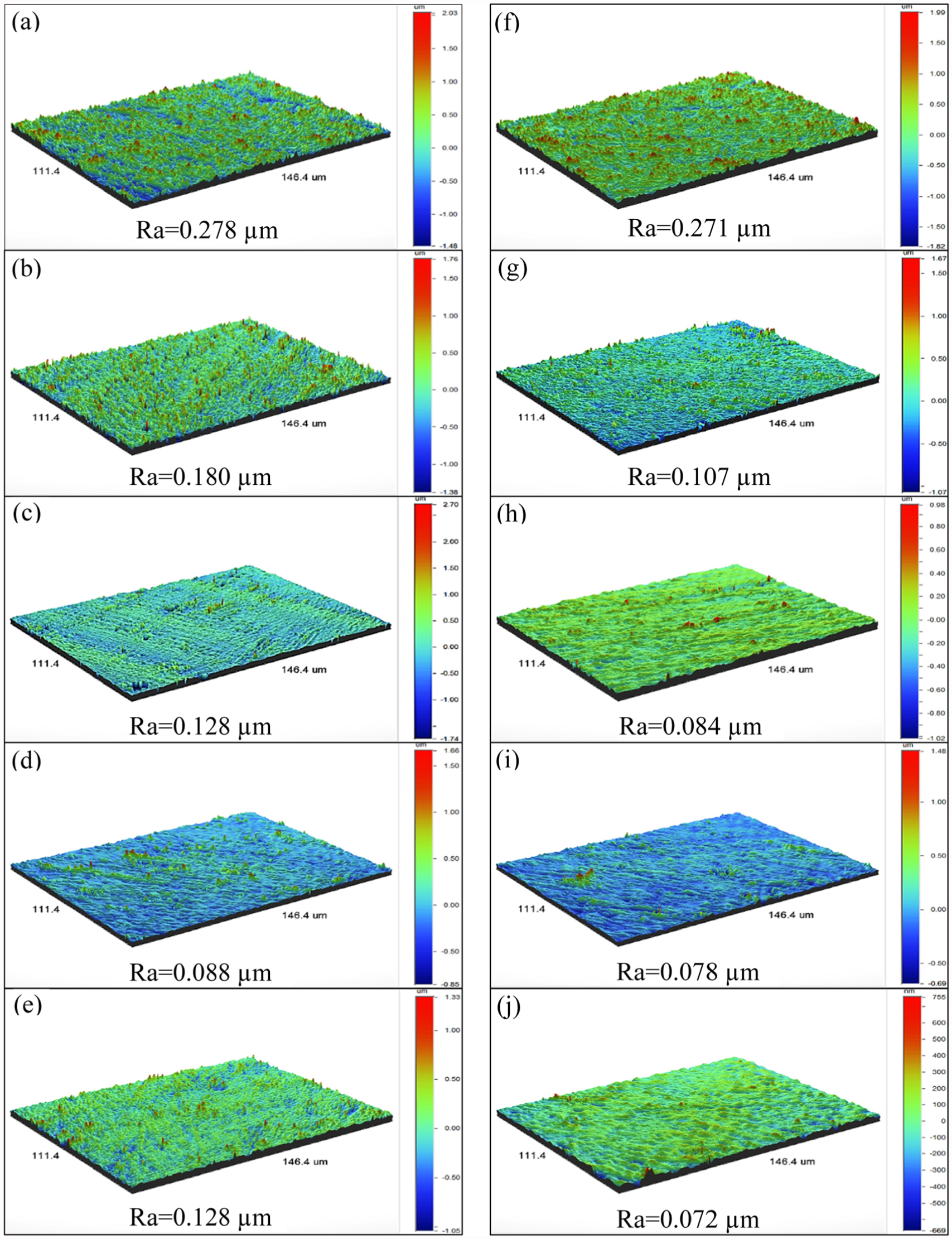
Variation in three-dimensional surface topography on Ti–6Al–4V samples: (a) initial roughness on specimen; (b)–(e) roughness on surface after 30, 60, 90, and 120 min of polishing with IBAP tool prepared at −6 °C; (f) initial roughness on specimen; (g)–(j) roughness on surface after 30, 60, 90, and 120 min of polishing with IBAP tool prepared at −4 °C.
From the results presented in Figure 10, it is clear that IBAP tool is seen to be more effective when it is prepared at a temperature of −4 °C. It can be attributed to the soft nature of IBAP tool prepared at −4 °C, having lower bonding strength and higher coefficient of friction compared to these properties on the tool prepared at −6 °C. This can also be attributed to the release of abrasive particles from bond material, that is, self-dressing ability with a reasonable wear rate and can also enhance its polishing performance and life.
Conclusion
In this work, the mechanical and tribological properties of IBAP tool such as hardness, coefficient of friction, and wear rate were determined for the tools prepared at different temperatures between −10 °C and 0 °C. The IBAP tool prepared with low-temperature coolant supply unit with VCR system is capable of freezing the slurry into IBAP tool and maintain it at any temperature between −10 °C and 0 °C. The characterisation results have shown that the hardness of IBAP tool decreased with increasing temperature. In fact, the tool prepared at −10 °C and −8 °C possessed very high hardness, whereas the tool prepared at −6 °C and −4 °C has medium hardness. The IBAP tool prepared at −2 °C and 0 °C has the least hardness and is very soft. The tribological studies have shown that coefficient of friction between the work surface and the IBAP tool, prepared at −8 °C and −6 °C, is very less compared to that of the tool prepared at other temperatures. The wear rate of IBAP tool, prepared at −10 °C, is negligible, and the tool prepared at −2 °C has the maximum wear rate. Therefore, this study clearly showed that IBAP tool prepared at −4 °C is found to have sufficient hardness with a reasonable wear rate that can be employed for effective polishing of the work surfaces for a long duration. Detailed polishing studies on Ti–6Al–4V alloy samples with IBAP tool, prepared at −6 °C and −4 °C, showed that the tool prepared at −4 °C is seen to be more effective, yielding about 72% improvement of finish (Ra) during 90 min polishing duration.
Footnotes
Declaration of conflicting interests
The author(s) declared no potential conflicts of interest with respect to the research, authorship, and/or publication of this article.
Funding
The author(s) received no financial support for the research, authorship, and/or publication of this article.