
Abstract
The blank of large complex surface parts such as aircraft skin parts is formed by roll–bending process, which always introduces a big shape deviation between actual blanks and the desired ones. The cutting tool path for the blank machining planned based on the nominal digital model of the part may scrap the part due to the shape deviation. In order to address this issue, laser inspection method is used to inspect the blank before machining to obtain the actual shape of the blank which can be used as a reference for cutting tool path generation in addition to the nominal digital model of the part. While the laser inspection device posture adjustment is an important factor for inspection precision, it should be intensively focused. The difficulty of the laser inspection device posture adjustment optimization is that it can only be performed based on the nominal digital model of the part, while the real inspection object is the actual blank whose real shape is unknown, which may lead to the inspection precision disqualification. In order to address the above difficulty, the actual blank profile is first constructed with a few of laser inspection points obtained by rough inspecting. An inspection path planning method is proposed based on the actual blank profile. A genetic algorithm is used to optimize the pendulum angles of the laser inspection device based on the inspection path and the actual blank profile, and the optimized postures of the actual blank can be calculated based on the pendulum angles. The proposed method of this article is verified by the inspection of an aircraft skin part, and the experiment results show that this method can ensure the final inspection precision.
Keywords
Introduction
Large complex surface parts, such as aircraft skin parts, are characterized with thin-walled structure, weak rigidity, complex shape, and varying curvature.1–3 There is always a big shape deviation between actual blanks formed by roll–bending process and the desired ones for large complex surface parts. According to a survey into some Chinese aviation manufacturing enterprises, the shape deviation between actual blanks and the desired ones can be up to ±7 mm. In order to address this issue, the blanks should be inspected before machining to obtain the actual shape, which can be used as a reference for cutting tool path generation in addition to the nominal digital model of the part. Laser inspection method has been widely used in large complex surface part inspection4–8 because of its high efficiency, while the posture adjustment of a laser inspection device should be intensively focused as it is an important factor for inspection accuracy. The difficulty of the laser inspection device posture adjustment optimization is that it can only be performed based on the nominal digital model of the part, while the real inspection object is the actual blank whose real shape is unknown, which may lead to the inspection precision disqualification. A variety of inspection random errors are introduced due to the factors such as material, color and roughness of the measured surface, and the capabilities of the machines on which the laser scanners are mounted.9,10 The inspection random errors which are difficult to accurately control in the inspection process can affect the inspection precision seriously.11–13 An effective way to ensure the final precision is to reduce the inspection errors which can be under control.
It is necessary to consider the constraints, such as the view angle, the field of view, and the depth of view of the laser inspection device during the inspection process. An inspection posture is set by considering the inspection constraints; if it cannot satisfy the constraints, a new posture should be calculated to continue inspecting, 14 while the adjustment may increase the inspection error. 15 The inspection errors can be controlled to ensure the final precision if the posture adjustment of the laser inspection device is optimized.
Regarding the research in posture adjustment optimization of the laser inspection device for large complex surface parts, it has been intensively focused by academic community. The related researches can be classified into two categories according to inspection objectives.
Inspection device posture adjustment optimization of three-dimensional parts based on visibility
The inspection device posture adjustment optimization of three-dimensional (3D) parts has been studied by some scholars. 16 Isheil et al. 17 proposed an error correction procedure based on an experimental process which considered the orientation between the sensor and the surface, and the posture adjustment of laser inspection device is optimized to reduce the inspection errors. Derigent et al. 18 presented a method to determine the 3D digitizing strategy for a mechanical part using a plane laser sensor, and a new approach based on the Minkowski operations is used to calculate the visibility of the different faces of the B-Rep model of the part; the minimum set of directions required to entirely digitize the part is computed to optimize the posture adjustment of laser inspection device. Fernández et al. 19 presented a methodology to develop an automatic process planning system applied for scanning parts with free-form surfaces using a laser stripe system mounted on a coordinate measuring machine (CMM). In order to reduce scanning time related to laser orientation changes, part triangles must be classified into a set of clusters based on their common visibility orientations. Mahmud et al. 20 proposed an inspection path planning method of a laser scanner with control on the uncertainty for 3D parts, where the concept of visibility is used from the computer-aided design (CAD) model of the inspected part to find a correct sensor guidance in a metrological point of view. Wang et al. 21 proposed an empirical study which experimentally investigates the outlier formation characteristics in relation to the scanning orientation of the laser probe, where the visibility is used to optimize the inspection device posture adjustment to reduce the occurrence of outliers.
The inspection device posture adjustment optimization of surfaces based on inspection points
The inspection device posture adjustment optimization of surfaces has been studied by some scholars.22,23 Mehdi-Souzani and Lartigue 24 proposed a scan planning strategy for a general digitized surface, where the new scan paths for an optimal digitizing are calculated including optimal orientation search by considering quality criteria, unsatisfactory quality zones, and digitizing gaps. Lee and Park 25 proposed an algorithm which leads to the automation of laser scanner–based inspection operations, where some laser scanners are operated by mounting the probe on a three-axis CMM, and the parts are clamped on a rotary table. Son et al. 26 proposed an automated measuring system for parts with a free-form surface, where a hardware system consists of a laser scanning device and setup fixtures that can provide proper location and orientation for the part to be measured. Son et al. 27 also came up with a new method for scanning a complex surface model with multiple patches, where the scan direction is determined by calculating the global mean vector of the sampled points that belong to a group. Ai et al. 28 presented a scanning path optimization method for wing panels based on a genetic algorithm, where the scanning process is divided into two actions of alternating motion combination for scanning measurement and attitude adjustment.
The methods reviewed above have provided technical references for posture adjustment optimization of the laser inspection device. While some research gaps still exist in studies on the inspection of large complex surface parts. For the first method mentioned above, the inspection device posture adjustment of 3D parts with corners can be optimized based on the visibility, which cannot be applied to the large complex surface parts. For the second method, the inspection device posture adjustment of surfaces can be optimized based on the nominal digital models, which does not consider the problem that the real inspection object is the actual blank whose real shape is unknown, and it may introduce the inspection errors, even it is difficult to ensure the inspection precision.
In this article, a posture adjustment optimization method of the laser inspection device for large complex surface parts is proposed. In contrast to traditional posture adjustment optimization methods where the real shape of the actual blank is not considered, a profile inspection rule is made to inspect the blank roughly to obtain the profile of the actual blank in this article. An inspection path planning method is proposed to determine the movement path of the inspection device based on the profile of the actual blank. A genetic algorithm is used to optimize the pendulum angles of the laser inspection device in the direction of U and V based on the inspection path and the actual blank profile, and the optimized postures of the whole actual blank can be calculated based on the pendulum angles. The aircraft skin part is one of the large complex surface parts, which is characterized with thin-walled structure, weak rigidity, complex shape, and double curvature. A further study is made on the inspection device posture adjustment optimization for large complex surface parts by taking an aircraft skin part as an example. The flowchart of this optimization method is shown in Figure 1, where the profile of the actual blank should be obtained first by inspecting the blank roughly. Then, the movement path of the inspection device can be determined based on the profile of the actual blank. Finally, the pendulum angles of the laser inspection device in the direction of U and V can be optimized based on the inspection path and the actual blank, the optimized postures of the whole actual blank can be calculated based on the pendulum angles.
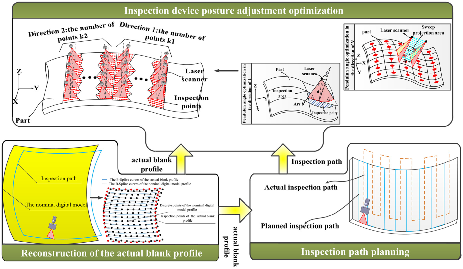
The flowchart of inspection device posture adjustment optimization method for large complex surface parts.
Reconstruction of the actual blank profile
The key of the laser inspection considering the real shape of the actual blank is to reconstruct the digital model of the blank. A profile inspection rule is made to plan an inspection path to inspect the blank roughly to obtain the real shape of the actual blank quickly. The deviation between the actual blank and the desired one can be analyzed based on the inspection data. The actual blank is reconstructed based on the deviation.
The profile inspection rule should satisfy the following conditions to reduce inspection time and ensure the inspection efficiency: (1) the integrality of the blank profile inspection should be guaranteed and (2) the redundant scanning region should be reduced as much as possible to save data processing time. The profile inspection path can be planned based on the nominal digital model of the part. The data obtained by rough inspection are processed to eliminate the redundant inspection points, which lays a foundation for the reconstruction of the actual blank.
The essential idea of the actual blank profile reconstruction is to change the shape of the nominal digital model profile based on inspection data to make it approximate to the actual blank profile. In order to achieve this, the profile of nominal digital model can be reconstructed by B-spline surfaces fitted by B-spline curves, whose shape can be changed easily by changing the positions of the control points of B-spline curves.
In order to make the profile of the nominal digital model be reconstructed by B-spline surfaces, the profile of the nominal digital model should be discrete based on the distance between inspection points, B-spline curves are used to fit the discrete points, and B-spline surfaces are fitted by B-spline curves and then the profiles of the nominal digital model can be replaced by the B-spline surface. The deviation between the actual blank profile and the profile of the nominal digital models can be obtained indirectly by analyzing the distance between inspection data and the B-spline surfaces, which provides a basis for the movement of the control points of B-spline curves, as shown in Figure 2. The shapes of B-spline curves can be changed by moving the control points according to the characteristics of B-spline curves, and actual blank profiles can be reconstructed by B-spline surfaces fitted by the changed B-spline curves.
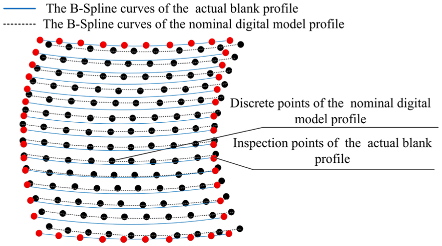
The B-spline curves reconstructed by inspection points.
Inspection device posture adjustment optimization method of aircraft skin parts based on actual blank profile
Inspection device posture adjustment optimization of aircraft skin parts based on the profile of the actual blank can ensure the final inspection precision. In this article, an inspection path planning method is proposed to determine the movement path of the inspection device based on the profile of the actual blank, the pendulum angle in the direction of U and V of each inspection position is optimized based on the inspection path and the actual blank profile, the inspection device posture of each inspection position is obtained by calculating the vector sum of two pendulum angles in the direction of U and V of each inspection position, and then posture adjustment optimization of the inspection device is achieved.
An inspection path planning method based on the profile of the actual blank
Inspection path planning based on the profile of the actual blank is to determine the movement path of the inspection device, which lays a foundation for the pendulum angle optimization in each inspection position. How to set the distance between two adjacent inspection paths is a problem to be solved for realizing inspection path planning to ensure that there is no un-inspected area between two adjacent inspection paths and the overlap inspection region is the least, which are very important to improve the inspection quality and efficiency.
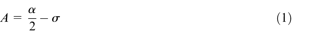
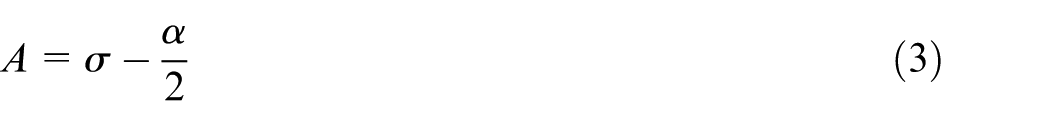
The premise of the adjacent inspection path distance setting is to ensure that there is no uninspected area between two inspection paths and the repeated inspection region is the least; thus, the distance should be less than the least distance between two inspection paths. The expression of the least inspection distance between two adjacent inspection paths has two forms according to the different intersection angles between the normal of the inspected surface at each inspection point and the shortest incident beam, the first one is shown in Figure 3. Angle A is shown as follows
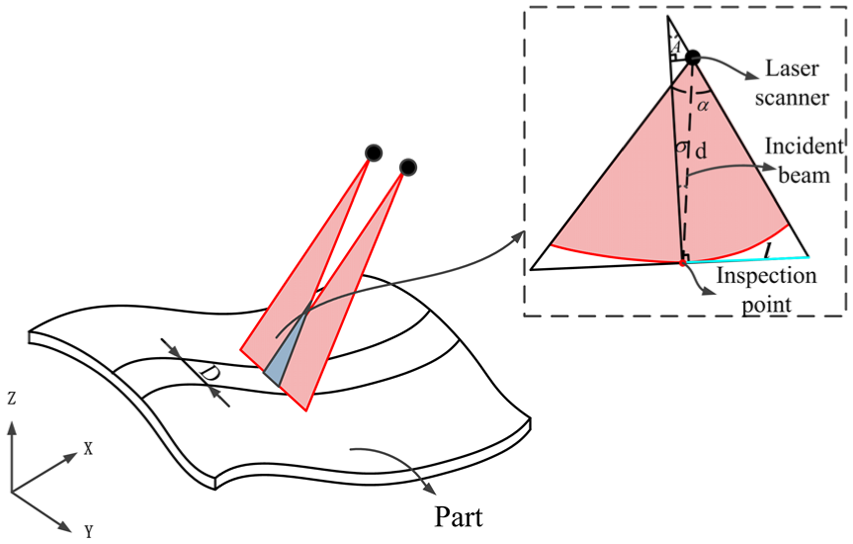
The distance between two adjacent inspection routes in the first form.
The least inspection distance between two adjacent inspection paths can be expressed as follows
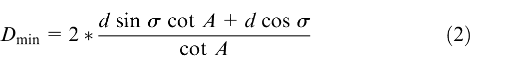
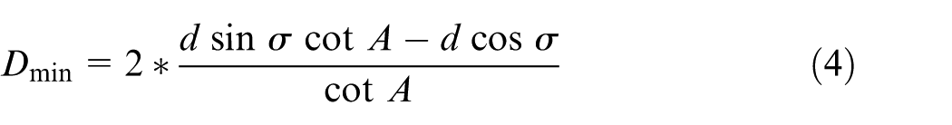
The second case is shown in Figure 4. Angle A is shown as follows
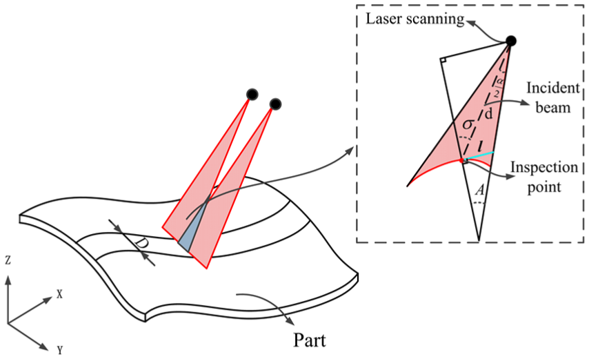
The distance between two adjacent inspection paths in the second form.
The least inspection distance between two adjacent inspection paths can be expressed as follows
Thus, the distance of two adjacent inspection paths

In order to ensure that the laser probe can travel along a path without collision. The actual inspection path can be obtained by offsetting the inspection path a distance from the surface.
Pendulum angle optimization method of aircraft skin parts based on the inspection path
The pendulum angle is the inspection device rotary angle during the inspection process, more times of the inspection device posture adjustment may cause the laser scanners to install on more times, which may introduce the dynamic error of the machines and reduce the inspection precision. A genetic algorithm is introduced to optimize the pendulum angles based on the inspection path and the actual blank profile, and the pendulum angles of each inspection position in the two directions are calculated based on the genetic algorithm models. 29 The optimized postures of the whole blank can be calculated based on the vectorial sum of these two pendulum angles of each inspection position. The direction toward which the laser scanner is moving is V, and the direction perpendicular to V is U.
The genetic algorithm model for the optimization of pendulum angles in the direction of U
The optimization of pendulum angles in the direction of U is the key to the inspection device posture adjustment optimization. A phenomenon found by an industrial survey and the further study of 3D laser scanning technology is that the times of inspection device posture adjustment are inversely proportional to the inspection area of every inspection posture when the area of inspected surface is determined. The area St is represented as follows

where St represents the total area of inspected surfaces, N represents the inspection device posture adjustment times, and

where
Linear laser can be emitted by the inspection device during the inspection process, each laser beam is composed of many laser points, and each laser point is corresponding to an inspection point on the inspection surface. In order to scan the whole surface successfully, the inspection device should meet the following constraints: (1) the scan inclination angle
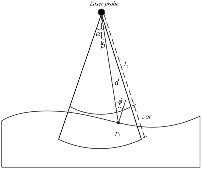
The constraints of laser scanning.
The inspection area Sa of each inspection posture can be expressed as follows based on the above-mentioned constraints

where
The region area is so small that it can be approximated to a rectangle; thus, the region area of each inspection point Sp0 can be expressed as follows

where a represents the geodesic distance between two laser beams and b represents the laser beam length of each inspection point, as shown in Figure 6.
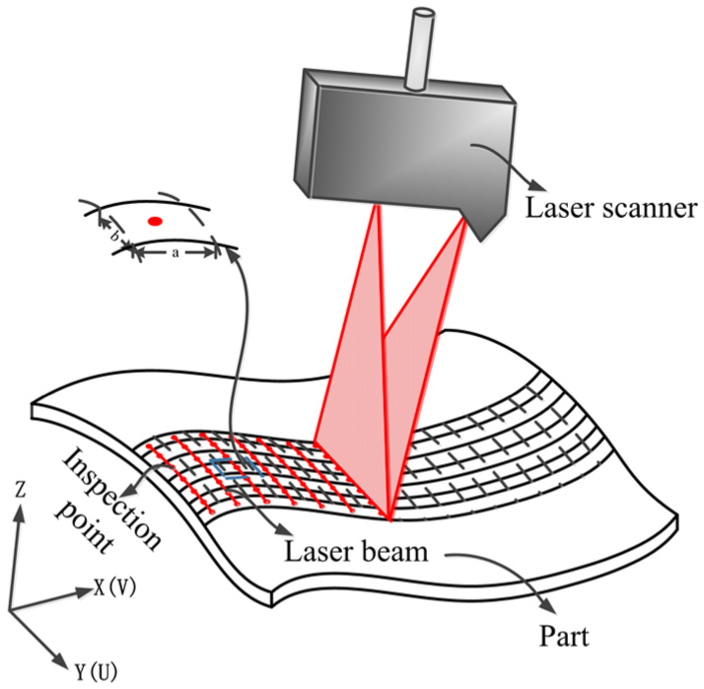
Laser scanning in the direction of U.
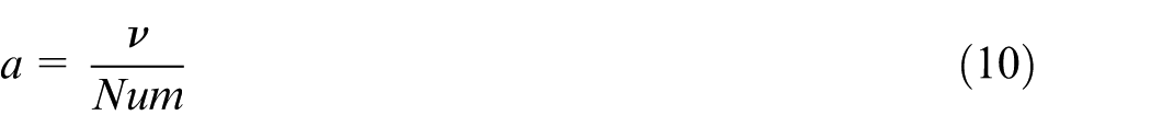
The geodesic distance a between two laser beams can be calculated according to the machine tool feed rate
The arc length b can be calculated in sections to reduce the computational difficulty, and each arc length is so small that it can be approximated to a line, and b is shown as follows

where la and lb represent the length of two straight lines the arcs approximated to.
The length of the two straight lines la and lb can be calculated according to the inspection angle


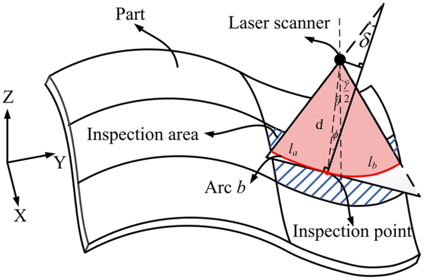
The inspection area at each inspection point in the direction of U.
The length of arc b can be calculated by substituting equations (12) and (13) into equation (11), and the length b is shown as follows

The region area of each inspection point can be expressed as
The pendulum angles at each inspection point can be expressed as follows
The inspection area of each inspection posture can be calculated according to the inspection area of each inspection point, and the area Sa is represented as follows
where the inclination angle

where the angle
Equation (17) can be represented as follows according to equation (18)
The optimal pendulum angles in the direction of U should be chosen to make the inspection area of each inspection posture the largest to obtain the least times of the inspection device posture adjustment and reduce the uncertainty during the inspection process, which can ensure the final inspection precision. In other words, it is necessary to obtain the maximum value of the function

where

Constraint conditions
where
The process of genetic algorithm should meet the following conditions: (1) the real number coding method is adopted; 30 (2) initial population should be established iteratively until it reaches to the population size n, where n = 200; (3) the mutation, crossover, and selection are operated iteratively for m times to obtain the optimal solution, where m = 100.
A genetic algorithm model for optimization of pendulum angles in the direction of V
The optimization of pendulum angles in the direction of V is also the key to the inspection device posture adjustment optimization. It turns out that the sum of the sweep projection area is the same when the area of the inspected blank is determined. The sweep projection area is referred to the area formed by the sweep area projected on the x–z plane, and the sweep area is generated by moving the inspection device during the inspection process as shown in Figure 8. If the sweep projection area of each inspection posture is the largest, the times of inspection device posture adjustment in the direction of U are the least.
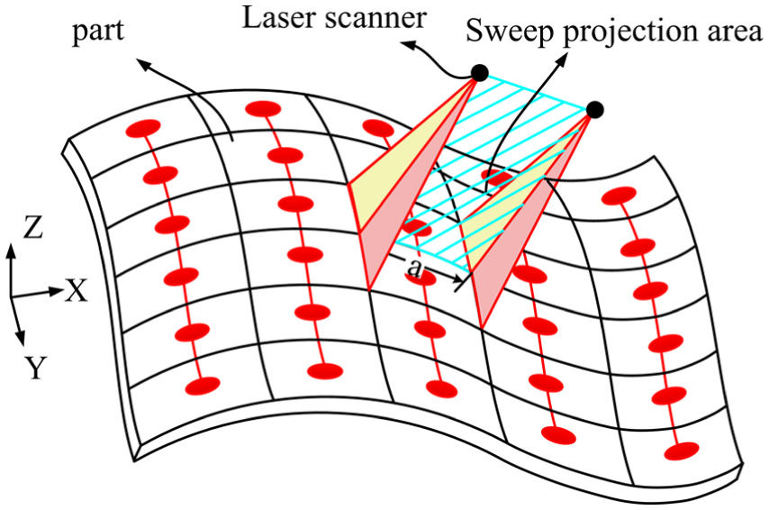
Laser scanning in the direction of V.
According to the relations between the total sweep projection area and the times of inspection device posture adjustment, the area

where
The area

where
The pendulum angle C should be in the allowable range, whose reference is the vertical direction; if the angle spins anticlockwise, it is plus; otherwise, the angle is minus. The distance between the inspection device and inspection points should be in the range of the depth. The sweep projection area

where
The geodesic distance a between two laser beams can be calculated based on the equation (10). The sweep projection area of each scanner point is calculated based on the distance a; the pendulum angle C; the distance d; and the angles
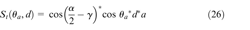
where
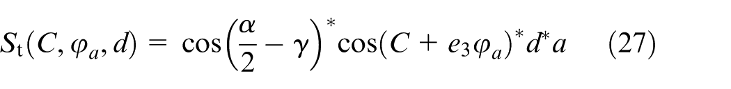
where
The inspection area at each scanner point in the direction of V.
The optimal pendulum angles in the direction of V should be chosen to make the sweep projection area of each inspection posture the largest to obtain the least times of the inspection device posture adjustment and reduce the uncertainty during the inspection process, which can improve the inspection precision and efficiency. In other words, it is necessary to obtain the maximum value of the function

where
Equation (29) can be changed and the optimized model can be represented as follows

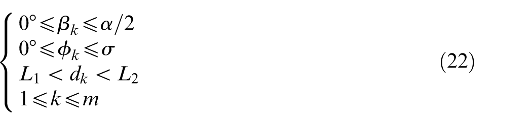
Constraint conditions
where
Case study
In order to validate the proposed method in this article, an inspection device posture adjustment software module for complex aircraft skin parts has been developed on CATIA V5 CAA platform with the language of VC++ based on the proposed approach of this article.
A typical civil aircraft skin part from a large aviation manufacturing enterprise is taken as an example to validate the method presented in this article. The Optiscan H-Class laser scanner is used for inspection path planning of the part, and the parameters of the scanner are shown in Table 1. The inspection path can be planned according to equations (2) and (4), where the inspection distance D between two adjacent inspection paths is 100 mm, field of view
The parameters of the laser scanner.
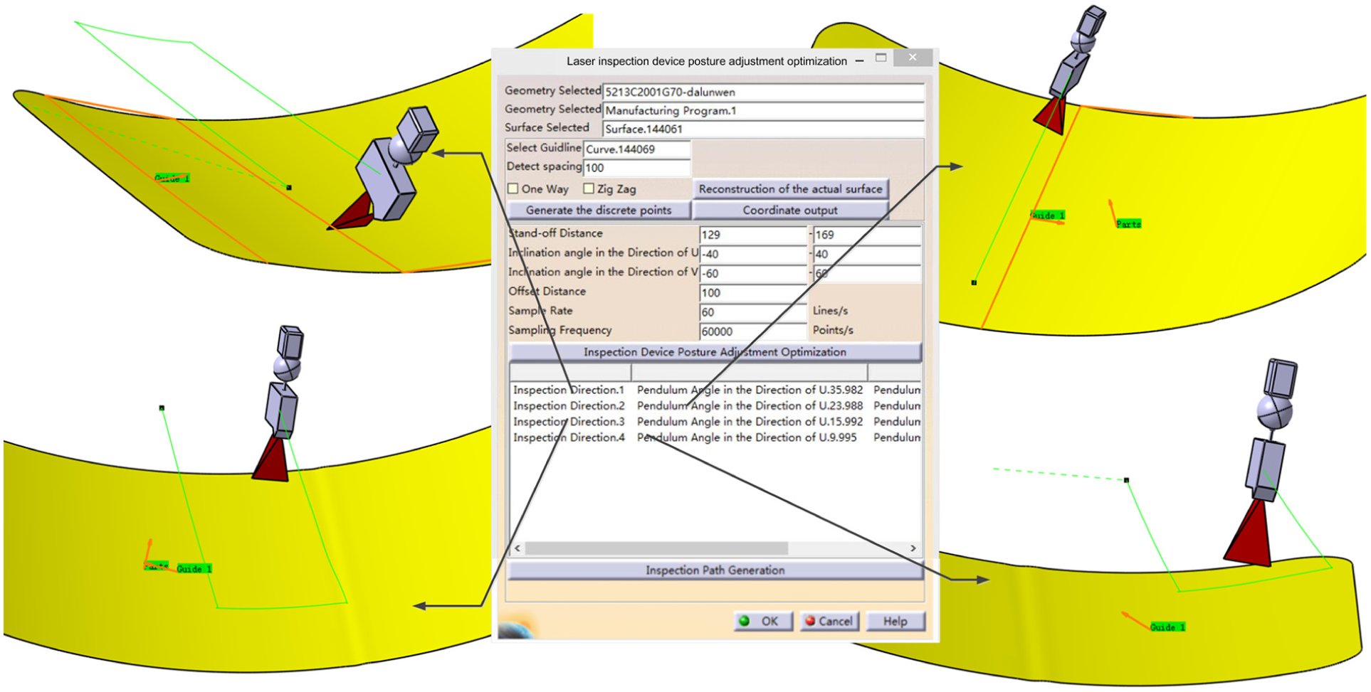
The inspection device posture adjustment optimization for aircraft skin parts.
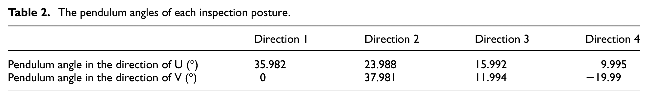
The pendulum angles of each inspection posture.
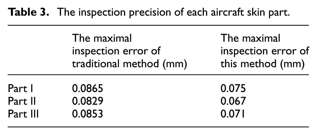
In total, three typical aircraft skin parts are selected to validate the inspection precision. The inspection precision is difficult to be estimated because of the lack of actual blank digital models of aircraft skin parts. The online contact inspection points which have a high inspection precision are taken as a reference. The distance between the surfaces fitted by the contact inspection points and the inspection points obtained by this inspection method is compared with the distance between the surfaces fitted by the contact inspection points and the inspection result obtained by the traditional inspection device posture adjustment optimization method. The comparison of inspection precision is listed in Table 3. The requirement of inspection precision in aviation manufacturing enterprise is ±0.08 mm, and according to an industrial survey, the method proposed in this article can meet the requirement, and the inspection precision is improved by an average of 16% compared with the traditional method.
The inspection precision of each aircraft skin part.
Conclusion
A posture adjustment optimization method of laser inspection device for large complex surface parts is proposed. The following achievements are realized by this article: (1) an actual blank profile reconstruction method based on a rough inspection is proposed; (2) an inspection path planning method based on the actual blank profiles is proposed to determine the movement path of the inspection device; and (3) a pendulum angle optimization method of large complex surface parts based on a genetic algorithm is proposed according to the inspection path and the actual blank profiles, and the optimal inspection angles in the direction of U and V are calculated by solving the genetic algorithm model. Our future work will consider other optimization goals during the inspection process of large complex surface parts, for example, the shortest inspection path.
Footnotes
Appendix
Declaration of conflicting interests
The author(s) declared no potential conflicts of interest with respect to the research, authorship, and/or publication of this article.
Funding
The author(s) disclosed receipt of the following financial support for the research, authorship, and/or publication of this article: The research work presented in this paper was primarily supported by the major project Jointly Funded with the National Natural Science Foundation of China and China Aerospace Science and Technology Corporation (Ref. U1537209), the National Natural Science Foundation of China (Ref: 51375239), Jiangsu Province Outstanding Youth Fund (Ref: BK20140036).