
Abstract
Hard and brittle materials like glass and ceramics are highly demanded in modern manufacturing industries. However, their superior physical and mechanical properties lead to high cost of machining. Ultrasonic machining has been regarded as one of the most suitable fabrication techniques for these kinds of materials. A smoothed particle hydrodynamics model was proposed to study the material removal mechanism of the ultrasonic machining in this study. Influences of abrasive materials and the particle shapes on the crack formation of work substrates were investigated using this smoothed particle hydrodynamics model. Experiments were also conducted to verify the simulation model. Both of the simulation and experimental results show that using hard and spherical abrasive particles is helpful to improve the material removal efficiency. This work was the first to demonstrate the crack formation mechanisms during ultrasonic machining with different abrasive particles using smoothed particle hydrodynamics, which is significant for improving the machining performance of the ultrasonic machining process.
Keywords
Introduction
As a response to the increasing needs for manufacturing mechanical, electrical, optical, and biomedical micro-parts or micro-structures on hard and brittle materials, developing precision and efficient micromachining techniques for these materials becomes extremely significant. However, due to the superior properties such as high hardness and strength, it is still a great challenge to efficiently machine hard and brittle materials. Abrasive-based ultrasonic machining (USM) has been widely proposed to meet the strict fabrication demands.1,2 In USM, an abrasive slurry generally comprising tough abrasive materials like silicon carbide and boron carbide flows through the working zone where a tool tip is vibrated. Loose abrasive particles under the vibrated tool tip are driven to impact the workpiece frequently, inducing countless tiny brittle fractures to remove materials away. When the tool size, abrasive particle size, and vibration amplitude are in micrometer scale, USM can be applied to micromachining.1–3 Even though the material removal rate in this process is reported to be low, 4 advantages like no thermal or chemical alterations on the machined surfaces make it more attractive than other micromachining methods such as electrical discharge machining (EDM) and laser beam machining (LBM) in some situations. Figure 1 shows a schematic of the basic USM system. The material removal is considered to be induced by the brittle fracture of workpiece materials, so micro-cracks are expected to be generated and retained on machined surfaces during USM. Such a crack would result in a strong variation in material strength 5 and accordingly influence the service life of products. It is therefore important to investigate the crack formation in USM for improving the machining performance.
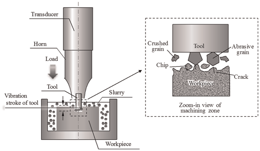
Schematic of USM.
However, due to the utilization of a slurry in USM, it is nearly impossible to observe the material removal in the machining zone directly. In addition, the initiation and propagation of cracks are within an extremely short time due to the ultrasonic tool vibration, which makes it more difficult for us to study the cracking process. Therefore, a new method for investigation on the crack formation in USM is demanded. The present authors 6 have proposed to simulate the material removal in micro-USM using a mesh free numerical technique, the smoothed particle hydrodynamics (SPH) method. 7 As no mesh is used, problems involved in large deformations and fractures, which may cause errors due to mesh distortion and tangling with the grid-based finite element (FE) method, can be effectively solved using this method. Consequently, SPH is suitable to study the material removal due to fracture failure of hard and brittle materials in USM. Problems like how the cracks initiate and how much the cracks propagate can be successfully studied.
A large number of process parameters exist in USM which would influence the machining performance, 8 and this enhances the difficulty in studying the material removal mechanism. Generally, slurry characteristics play a particular important role in USM. Experimental investigations have been conducted for revealing the influences of abrasive size, abrasive material, and abrasive concentration in previous studies.9–11 However, a complete understanding of their roles is still not clear due to the complexity of USM process. Considering that arguments on the abrasive shape have rarely been referred, both SPH simulations and experiments were conducted to study the influence of the abrasive type including its material and shape on USM in this study. The crack formation in the workpiece was investigated using SPH and its relation to the material removal was discussed. The machining efficiency and the machined surface quality were examined through the USM experiments for confirming the validity of SPH simulations.
Material removal mechanism of USM
Three main actions are believed to cause material removal in USM and have been summarized by previous researchers: 12 (a) mechanical abrasion by direct hammering of the larger abrasive particles against the workpiece surface, (b) micro-chipping by impact of the free-moving abrasive particles, and (c) cavitation erosion from the abrasive slurry. Figure 2 shows the three actions schematically. It is widely accepted that the direct hammering dominates the main material removal in USM. 13 Therefore, the hammering action by a single abrasive particle was created by SPH to simulate the crack generation in this study.
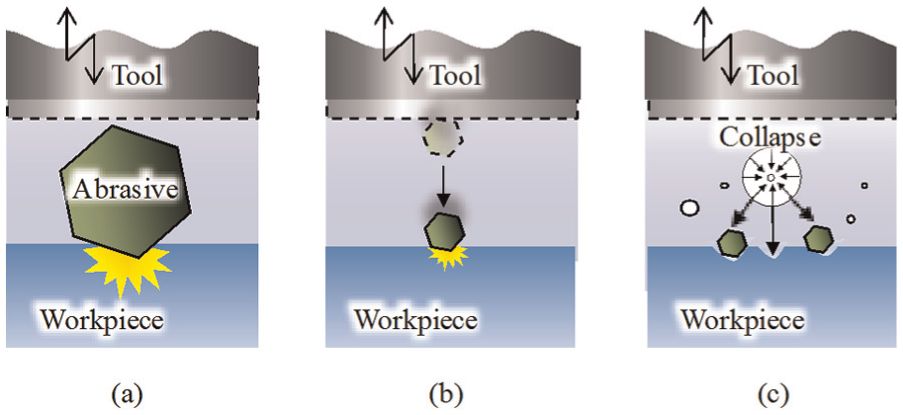
Schematic diagram of main material removal actions in USM: (a) hammering action, (b) impact action, and (c) cavitation erosion.
SPH simulation of USM
Crack formation in hard and brittle materials due to indentation
Central to the scientific evaluation of fracture in hard and brittle materials is to show the crack patterns through the indentation of hard and brittle surfaces. 14 Figure 3 shows the schematic view of essential features of basic indentation fracture systems. 15 A cone crack system is shown in Figure 3(a). The cone crack is typically generated by the elastic loading of spherical or flat-punch indenters (millimeter-scale). It forms into a surface ring as shown in broken line and finally becomes critical and propagates into a fully developed cone. Figure 3(b) depicts the median crack system. Loading by sharp indenters such as Vickers or Knoop diamonds, or excessive loading of blunt indenters, leads to the generation of a remnant plastic impression in the surface. 16 In the median crack system, a median crack nucleates from the plastic contact zone (shaded) and propagates parallel to the axis of loading. Also, in this system, radial cracks may be generated similarly parallel to the load axis. They initiate from the edge of the plastic zone close to the surface. The growth and coalescence of these cracks will finally urge a half-penny crack to be formed in the material. During the unloading, lateral cracks nearly circular in form generate beneath the deformation zone and propagate parallel to the surface as shown in the right side of Figure 3(b). Because the abrasive impact under one cycle of tool vibration stroke finishes in an extremely short time in USM, the indentation stress field may not be completely applied to this study. However, the names of the crack patterns mentioned above are utilized without changes in this work.
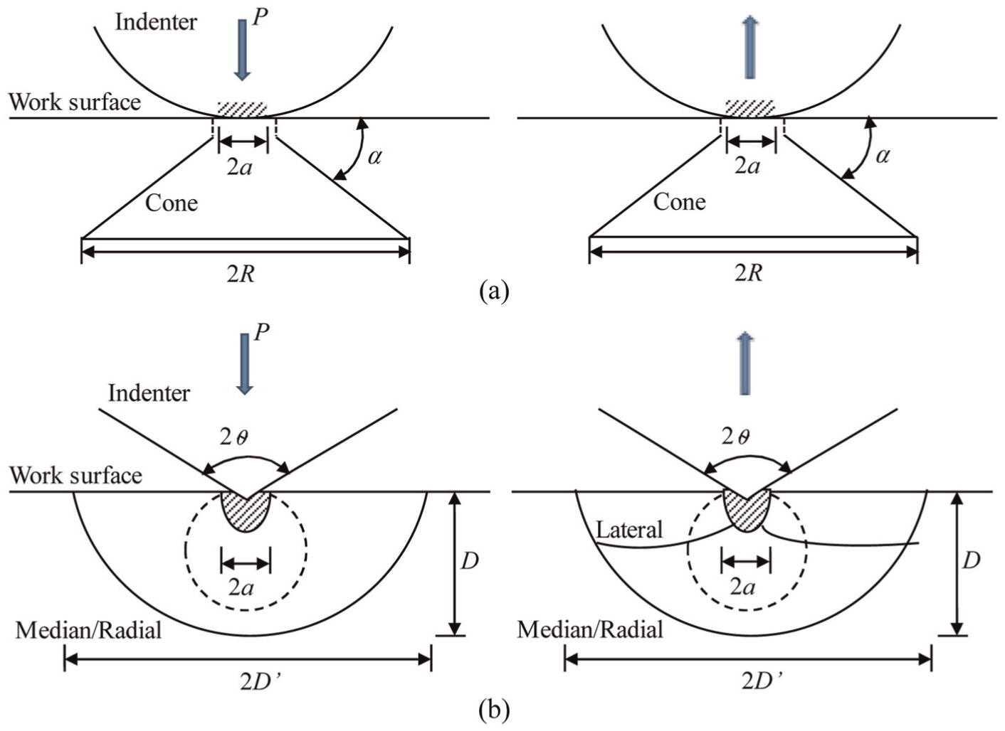
Schematic view of basic indentation fracture systems: (a) cone crack system and (b) median crack system.
SPH method
In SPH, a set of particles endowed with physical properties are distributed in the domain and used to express a continuum. Figure 4 shows a schematic diagram of SPH method. Each particle I (which is really an interpolation point) interacts with all other particles J that are within a defined distance 2h. The distance h is called the smoothing length.
17
To calculate the values of a continuous functions or its derivative at the particle I, the values at all particles J within 2h are weighted by a kernel function W (
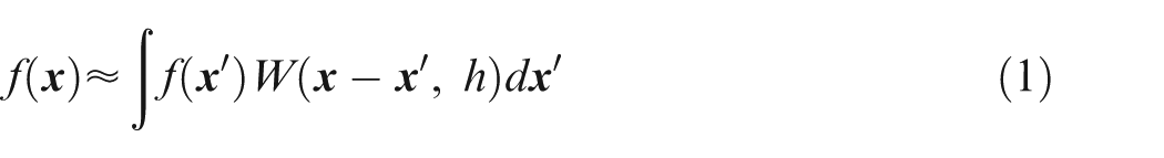
where f is a function of the three-dimensional position vector
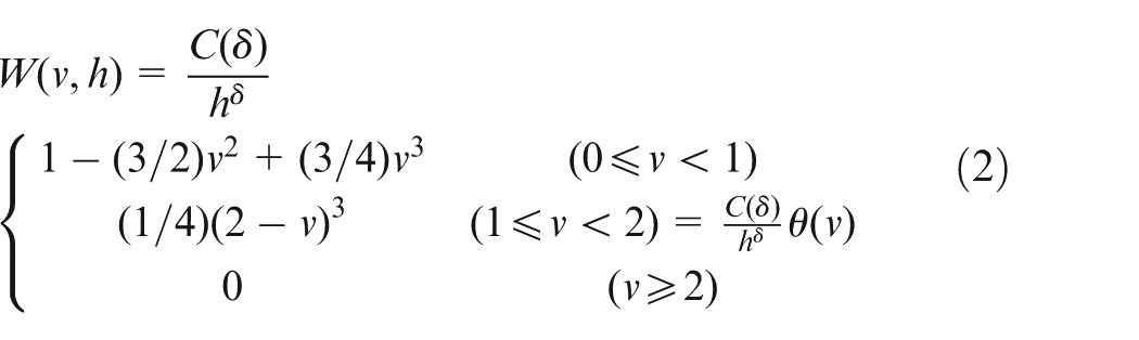
where
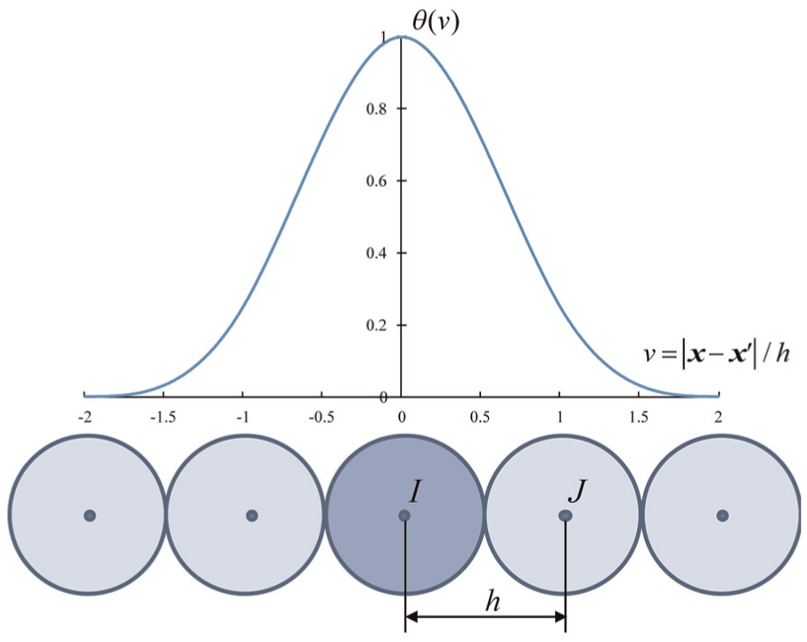
Schematic diagram of SPH method.
Simulation method
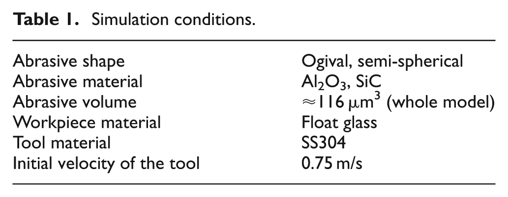
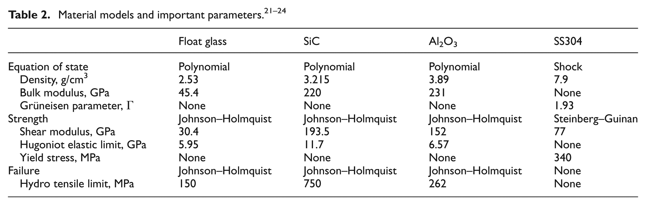
In USM, not all of abrasive particles are in the same shape, so they were classified into two main groups in this work. One group includes abrasive particles that possess sharp corners with many surface irregularities. The other group indicates abrasive particles on round surface without sharp corners. To model them, an ogival shape and a semi-spherical shape were built and represented abrasive particles with and without sharp corners, respectively. Figure 5 shows the snapshots of the initial state of the simulation models. To reduce the calculation time, only a one-quarter three-dimensional model was built with symmetric boundary conditions. Each model included a vibrated tool built with Lagrange FE mesh, one abrasive particle modeled with SPH, and a workpiece substrate constructed with both SPH and Lagrange FE mesh. The velocity condition of the tool vibration was applied to the nodes on the top surface of the tool. All nodes on the bottom surface and side surfaces of the workpiece were constrained in the direction of Z and X/Y axes, respectively. The smoothing length of SPH was set to be 200 nm. The FE size was 1 µm for workpiece. The deformation of the tool by the penetration of abrasive particles was neglected in this work, so the tool was regarded as a rigid body and not discretized into small elements. Through these models, the crack formation in the workpiece was investigated. The simulation conditions are summarized in Table 1. Float glass was used as the workpiece material. Silicon carbide (SiC) and alumina (Al2O3) were employed as the abrasive materials. Stainless steel (AISI: 304) was chosen as the tool material. The material models and important parameters are listed in Table 2. The Johnson–Holmquist material model 20 was utilized to simulate the brittle failure of the workpiece. In this model, the accumulated damage for fracture is expressed as
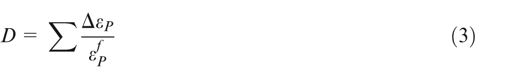
where ΔεP is the increment of equivalent plastic strain during one cycle of integration and
Simulation conditions.
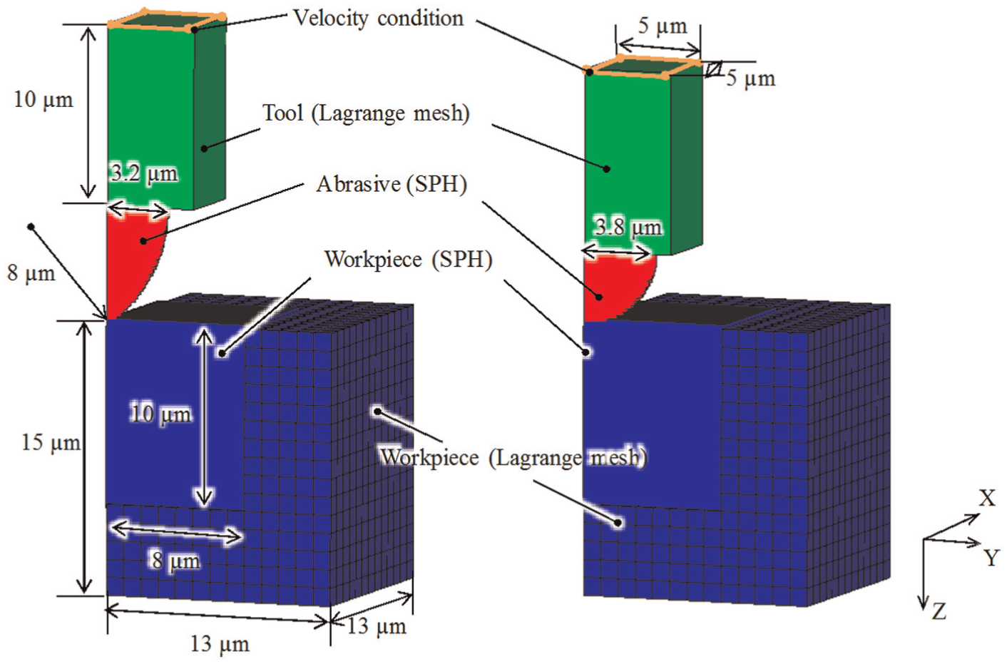
Simulation models.
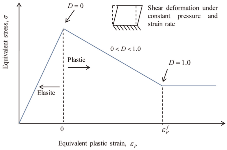
Physical explanation of damage and fracture of Johnson–Holmquist model.
Simulation results
Time-dependent simulation results for SiC abrasive particles along X-Z symmetric plane are shown in Figure 7. The right half is mirror images of the original model. The end of the downward stroke is the result after a calculation time of 2.5 µs. The gray, white, and black color illustrated in the figure represent elastic, plastic, and failure states, respectively. It should be noted that the gray/white elements just show an instantaneous elastic/plastic states at that point based on the von Mises yield criterion. The white elements those turned back to gray color during calculations do not mean a recovery of the material. However, once an element turns to black, which means the material is fractured and it never turns back to the other colors. After a calculation of 0.1 µs, a plastic region appears in the workpiece when using a semi-spherical particle. Median and radial cracks were formed from the plastic contact zone and extended with further penetration imposed by the tool. Then, with the unloading of the tool, the plastic region under the impact site was transformed into material failure in the form of a lateral crack. The width of the fracture range on the work surface approximates to 9.1 µm and the depth of the median crack extends to 5 µm ultimately. The same crack formation process is confirmed when using an ogival abrasive particle. However, the final depth of the median crack is 3.8 µm and the crack width on the surface is 4.6 µm. Both of them are smaller than those generated by a semi-spherical abrasive particle. It is also noted that the corner of the ogival abrasive particle was abraded faster comparing with the round surface of the semi-spherical particle.
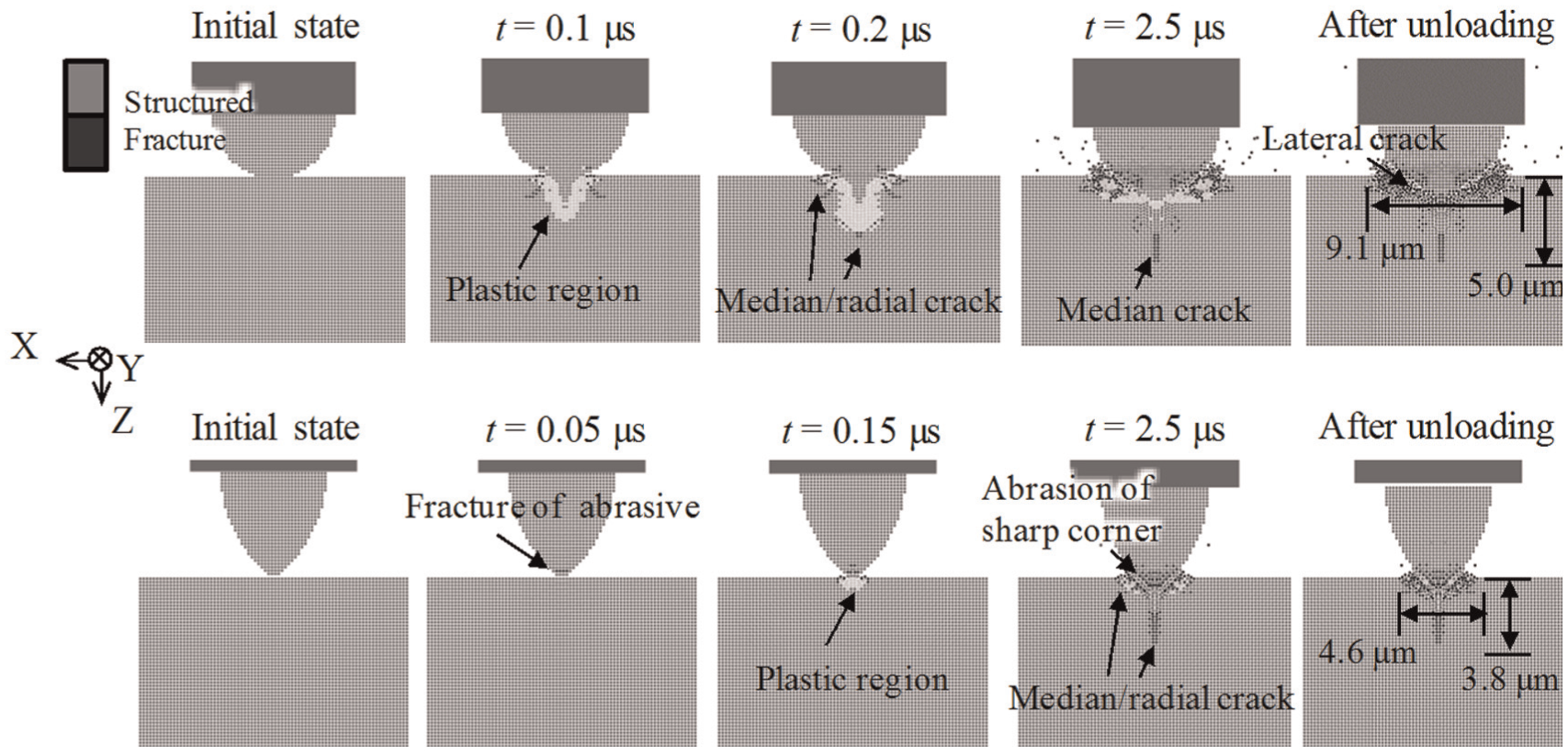
Simulation results when using SiC abrasive particles.
The simulation results for Al2O3 abrasive particles are shown in Figure 8. The median/lateral cracks are not observed for both semi-spherical and ogival abrasive particles. Instead, a cone crack was found to be formed beneath the impact site and finally extended up to 1.8 µm in depth when using a semi-spherical particle. On the other hand, only a tiny crack with a depth of 0.2 µm was generated in the workpiece when using an ogival particle. The crack widths on the work surfaces are 8.7 and 3 µm for semi-spherical and ogival abrasive particles, respectively. The cracks generated by the Al2O3 particles are smaller in size than those initiated by the SiC particles. On the other hand, larger fractures occurred in the Al2O3 particles of both semi-spherical and ogival shapes.
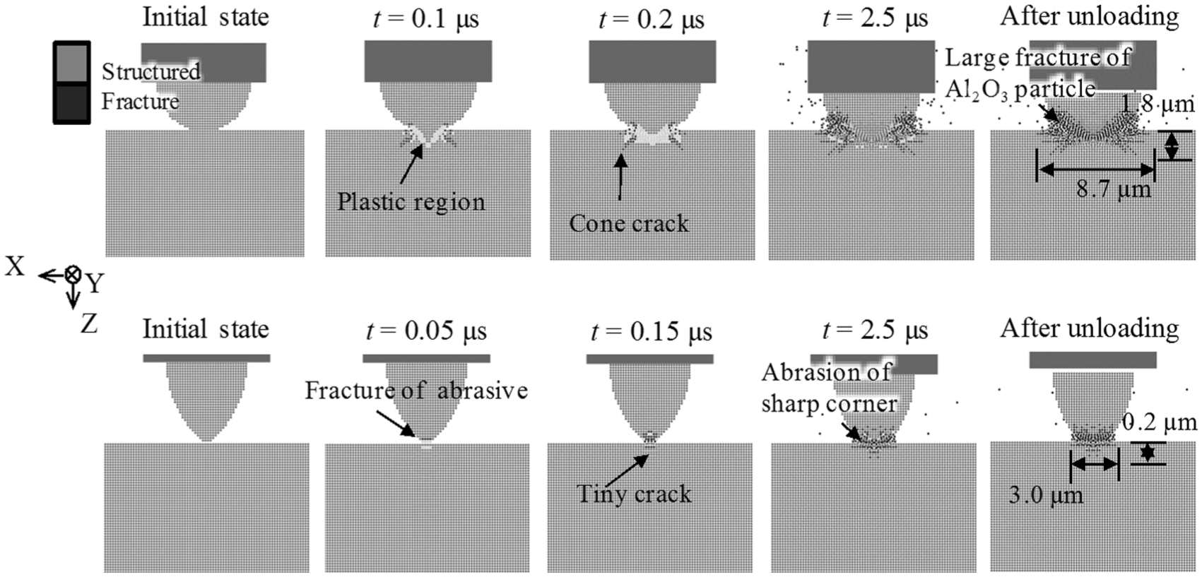
Simulation results when using Al2O3 abrasive particles.
Increasing stress levels in the subsurface are significant in initiating fractures and enhancing crack growth. 25 Generally, the magnitude of the stresses is proportional to the applied pressure. In USM, high contact stresses are developed in the subsurface of the workpiece hammered by abrasive particles due to the force of the vibrated tool. Therefore, even though the vibration condition (loading and unloading condition) is the same, the final pressure applied on the substrate would be decreased due to the fracture of abrasive particles. In the simulations, as the maximum tensile hydrostatic pressure of SiC is almost three times larger than that of Al2O3, the SiC abrasive resists fractures more easily. For this reason, high pressure was applied on the work surface and the crack size was larger when the SiC abrasives are used.
A large effect of the abrasive shape on the fracture of abrasive particles and workpieces was also noticed. The sharp corners of the ogival abrasive particle were abraded quickly and severely during the downward stroke of the tool. However, for the semi-spherical particle, few cracks were generated at the area in contact with the substrate and the growth of these cracks was slower, which ensures the pressure applied on the work surface to be high. As a result, large cracks are generated in the workpiece when semi-spherical abrasives are used.
Cracks initiated by the hammering of abrasive particles are considered to contribute greatly to the material removal in USM. 26 Larger cracks may lead to larger chip removal and increase the material removal efficiency. On the other hand, if cracks propagated seriously in the depth direction, they may be not removed completely and left on the machined surfaces finally. Therefore, the material removal efficiency is expected to be higher while the surface/subsurface cracks are anticipated to be increased when using harder and spherical abrasive particles according to the simulation results.
USM experiments using abrasives of different materials and particle shapes
Experimental setup
A stationary ultrasonic drilling machine (Model: SD-100K; Taga Electric Co., Ltd., Japan) as shown in Figure 9 was used for carrying out USM experiments. The machine has three linear XYZ-axes and one rotary B-axis. The three linear axes are numerically controlled with a maximum travel range of 100 mm and a minimum feed resolution at 0.1 µm. The maximum output of the ultrasonic machine is 45 W and the oscillation frequency ranges 61 ± 6.0 kHz.
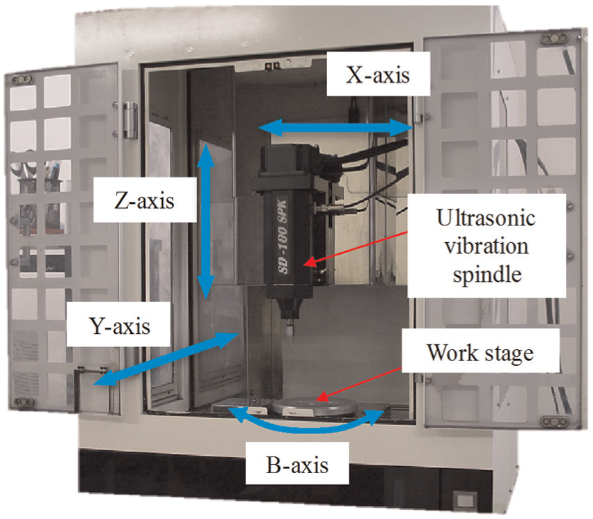
Experimental setup.
Experimental procedure and conditions
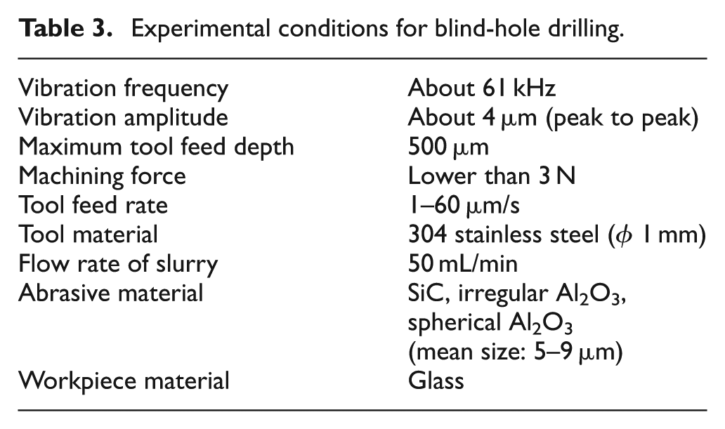
Abrasives used in the experiments are SiC particles of irregular shapes (Fujimi Corporation) and Al2O3 particles of irregular shapes and spherical shapes (Showa Denko Corporation). Figure 10 shows the micrographs of the abrasives observed using a scanning electronic microscope (SEM) (Model: SU1510; Hitachi Co. Ltd.). It can be found that both the irregular SiC and Al2O3 particles possess many sharp corners as shown in Figure 10(a) and (c). The distribution of particle sizes of all the SiC and Al2O3 abrasives was in the same level. Blind-hole drilling experiments on glass plates were conducted using the three types of abrasive particles with stop conditions when either the machining depth is bigger than 500 µm or the maximum machining force is larger than 3 N. Table 3 lists the detailed experimental conditions. Different feed rates were tried for verifying the influence of the abrasive type on machining efficiency. A load cell as shown in Figure 11 was used to trace the average machining force during USM drilling. The roughness of the machined surfaces was measured with a non-contact laser probe profilometer (Model: NH-3SPH; Mitaka Kohki Co., Ltd). To observe the remaining cracks on the work surfaces, the machined workpieces were etched in a buffered oxide etch solution of a combination of hydrofluoric acid and ammonium fluoride. The crack depths of the remaining cracks were examined after etching with the SEM.
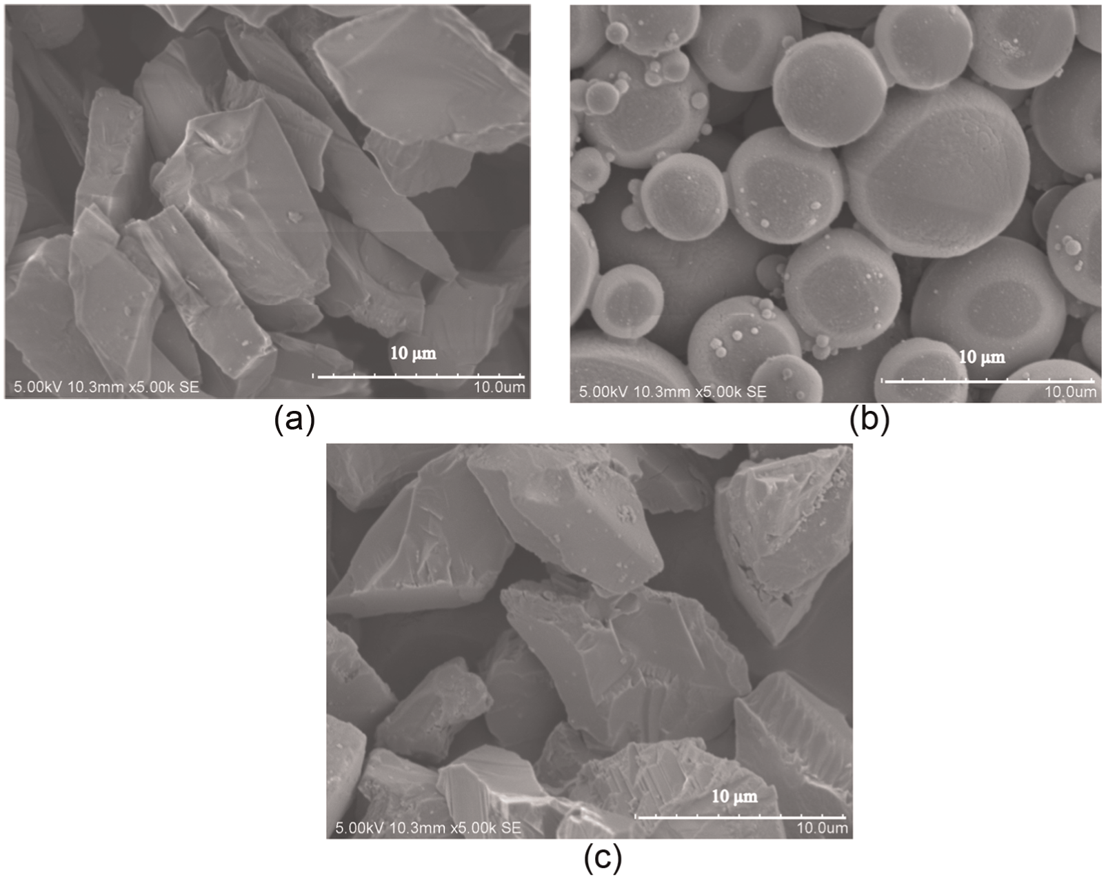
SEM micrographs of different types of abrasive particles: (a) irregular SiC particles, (b) spherical Al2O3 particles, and (c) irregular Al2O3 particles.
Experimental conditions for blind-hole drilling.
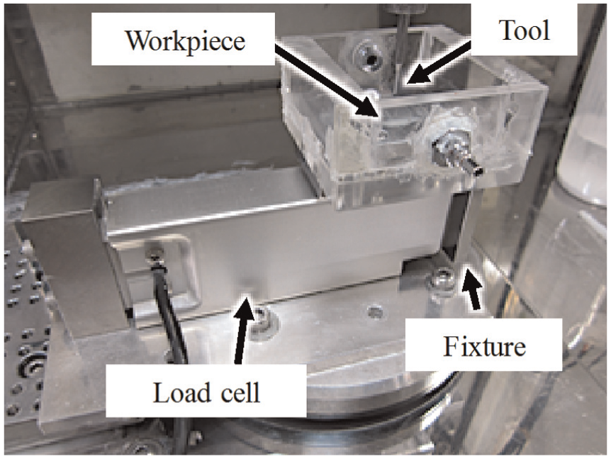
Load cell for machining force measurement.
Experimental results
The results of machining force when fabricating holes with different abrasive particles are shown in Figure 12. When a low feed rate was applied, the machining force for all three cases was stable and lower than 3 N except for a small increase at the start-up stage when using irregular Al2O3 abrasives as shown in Figure 12(a), which indicates that the material removal went on smoothly. However, when the feed rates were increased, the machining force for all the three cases rapidly increased as shown in Figure 12(b). The possible reason is that the material removal rates could not meet the high tool feed rates. In this situation, the machining gap between the tool and the workpiece becomes narrower, which is not enough for abrasive renewal and debris removal. This leads to a jamming in the machining gap and finally increases the machining force. If the material removal is sufficient to ensure the machining gap large enough, the jamming can be avoided and the tool feed can be fast. Therefore, the limit of the tool feed tells the material removal efficiency of USM.
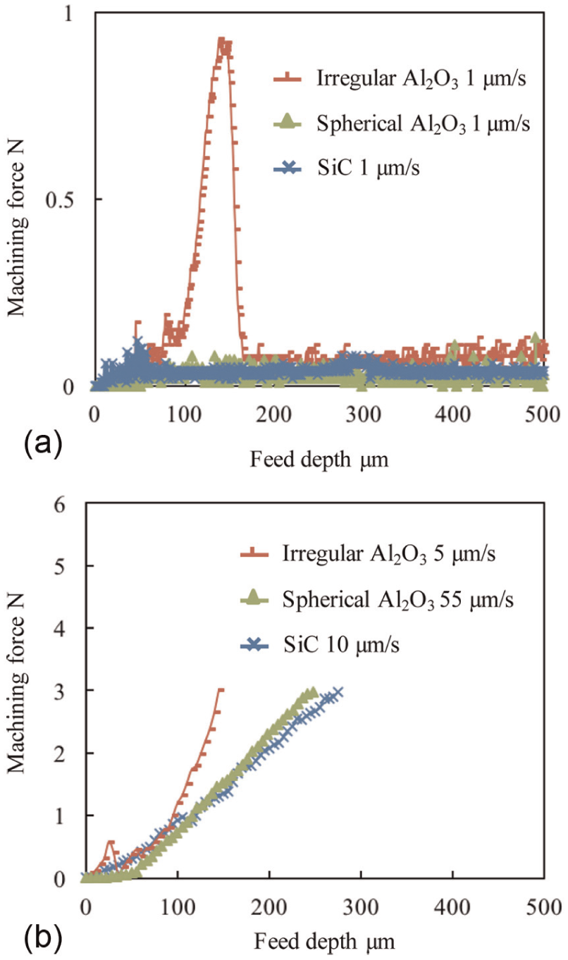
Machining force under different conditions: (a) low feed rate, (b) high feed rate.
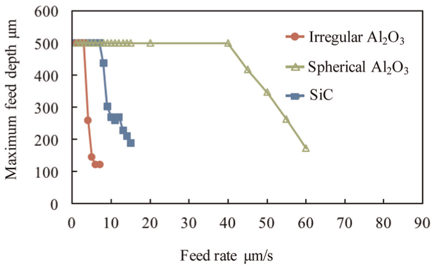
Figure 13 plots the maximum feed depth when the machining force reaches 3 N under different feed rates. If the feed depth reached 500 µm before the machining force increased to 3 N, the feed operation was intentionally stopped. The results show that the tool feed rate can be up to 40 µm/s to finish 500 µm feed when using spherical Al2O3 particles, while being 7 µm/s when using SiC particles and the lowest value of 3 µm/s when using irregular Al2O3 particles. In this study, the obtained maximum feed rates were used to evaluate the material removal efficiency of the USM, which thus can be ordered in magnitude as to be spherical Al2O3 particles, SiC particles, and irregular Al2O3 particles. These experimental results support the simulation results that using harder and spherical abrasive particles is helpful to improve the material removal efficiency.
Maximum feed depths under different feed rates.
The average roughnesses (Ra) of bottom surfaces of machined holes under a feed rate of 1 µm/s were examined, which are 1.57, 0.71, and 0.55 µm when using spherical Al2O3 abrasive particles, SiC abrasive particles, and irregular Al2O3 abrasive particles, respectively. The machined surface exhibits the highest roughness when using spherical Al2O3 abrasive particles, which indicates that large craters may be left on the machined surface if this type of abrasive particle is used in USM. The experimental result confirms the simulation predict that using spherical abrasives leads to larger chip removal from the workpiece material.
The cross-sections of holes drilled by USM were captured as shown in Figure 14. Micrographs on the left side show the close views of bottom surfaces, while those on the right side show the close views of wall surfaces. Cracks remaining on the machined surfaces were confirmed in all cases. It can be found that fewer cracks with smaller size were observed when using irregular Al2O3 abrasive particles, which explains the low material removal rate when using this kind of abrasive particles. In addition, cracks on bottom surfaces as shown in the figures extended to 1, 0.5, and 1.8 µm in depth with spherical Al2O3 particles, irregular Al2O3 particles, and SiC particles. Theses observed crack depths are comparable with the results calculated by the simulations. The cracks remaining on the wall surfaces are considered to be the propagations of median/radial cracks and cone cracks into the surrounding material at an angle to the loading axis.
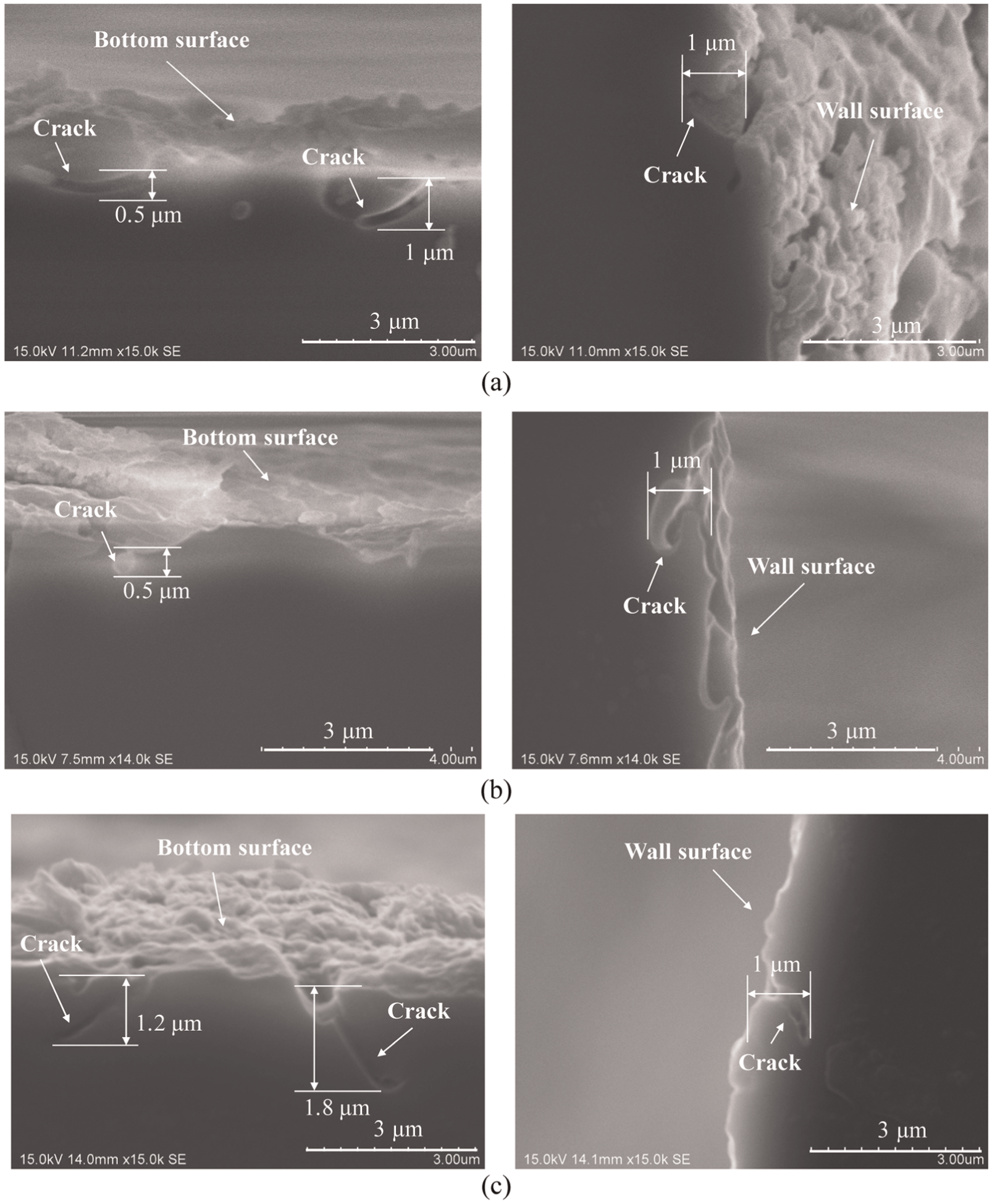
Cross-sections of machined holes using different abrasive particles of (a) spherical Al2O3 particles, (b) irregular Al2O3 particles, and (c) SiC particles.
Conclusion
In this study, the influence of abrasive material and particle shape on material removal in USM was investigated by simulation calculations and experimental verifications. The propagation of cracks in substrates and the fractures of abrasive particles in USM were demonstrated using an SPH model. However, the tool deformation and the tool-abrasive contact during USM process cannot be studied through the current model. To better understand the material removal in USM, further studies should be conducted to discuss the effects of the tool deformation and the real tool-abrasive contact area. The major conclusions of this work can be summarized as follows:
The crack formation in USM is strongly affected by the abrasive material and the particle shape. Larger cracks will be generated in workpieces when using harder abrasive particles possessing spherical shape.
The depths of cracks observed on the machined surfaces are comparable with the simulation results, which means the proposed SPH model is instructive for abrasive selection in USM.
The slurry comprising harder and spherical particles is helpful to increase the material removal efficiency. On the other hand, the larger cracks may be left on the machined surfaces as subsurface damages, which decreases the surface quality. Therefore, a balance between the machining efficiency and the surface quality is needed to be explored.
The machining force is an extremely important parameter for studying the USM efficiency. When the material removal process does not go on smoothly, the machining force increases irreversibly.
The simulation results imply that the resistance to abrasion of hard and spherical abrasive particles is higher, which results in a higher pressure applied on the work surface and then leads to generation of large cracks.
Footnotes
Declaration of conflicting interests
The author(s) declared no potential conflicts of interest with respect to the research, authorship, and/or publication of this article.
Funding
The author(s) received no financial support for the research, authorship, and/or publication of this article.