
Abstract
In immersed friction stir welding, the workpiece is fully immersed in the water during welding. This work illustrates the effect of welding speed on mechanical properties and microstructure. Friction stir welding joints were produced using AA2014-T6 at different welding speeds ranging from 80 to 125 mm/min with constant rotational speed of 1000 r/min in air and immersed water conditions. Results revealed that with an increase in welding speed, the tensile strength of joint increased, this is due to a reduction in heat input while using both air and immersed friction stir welding, which in turn reduces the dissolution of strengthening precipitates. Microstructure result showed that grain size decreased with an increase in welding speed due to less heat input at increased welding speed. The dissolution of strengthening precipitates weakened with an increase in welding speed in both air and immersed friction stir welding, leading to an increase in hardness value at the nugget zone. Maximum tensile strength was obtained at a welding speed of 100 mm/min in immersed friction stir welding and was around 17% higher compared with a maximum tensile strength obtained using air friction stir welding.
Keywords
Introduction
Friction stir welding is a process in which the material does not melt during welding, which prevents melting related defects. Friction stir welding process was invented at the Welding Institute, United Kingdom, in 1991. 1 Friction stir welding process has numerous benefits over fusion welding processes. Many heat-treatable aluminum alloys of 2xxx and 7xxx series which are extremely difficult to weld because of melting-associated defects can be welded easily using friction stir welding.2–4 Effect of tool pin geometry, tool rotational speed and welding speeds on the mechanical properties of joints in various aluminum alloys using friction stir welding is studied.5–7 The temperature produced during friction stir welding for joining aluminum alloys is below their melting point.8,9 The heat-treatable aluminum alloys of 2xxx series have a higher strength to weight ratio, which find widespread use in aircraft and aerospace engineering.5,10 During friction stir welding of heat-treatable aluminum alloys, their mechanical properties modified through dissolution of the precipitates. 11 The recent developments in friction stir welding focused on immersed friction stir welding to improve the tensile strength and mechanical properties by controlling temperature during welding and by obtaining fine grain microstructure. Benavides et al. 12 used liquid nitrogen during friction stir welding of AA2024 to decrease nugget zone (NZ) temperature during welding. Microstructure and hardness of thermo-mechanical affected zone (TMAZ) and heat-affected zone (HAZ) was improved during friction stir welding. Fratini et al.13,14 performed friction stir welding of AA7075-T6 with workpiece immersed in flowing water. Water cooling enhanced joint strength by reducing softening in the TMAZ area. Zhang et al. 15 studied joint performance of AA2219 alloys welded in immersed condition by varying the rotational speed. The authors observed that the joint strength reduced due to formation of block-shaped equilibrium θ precipitates from the base metal θ′ precipitates. The joint fracture pattern changed compared to the air friction stir welding. Water cooling during dissimilar friction stir welding reduces the intermetallic compound formations and hence improves the mechanical properties of the joint. 16 More uniform strength improvement observed in the thickness direction in the immersed friction stir welding compared to air friction stir welding. 17 Kishta and Darras 18 studied the effects of rotational speed and translational speed on underwater friction stir welding of 5083 marine-grade aluminum alloys. Several researchers12–25 reported advantages of various external cooling mediums like liquid nitrogen, water at room temperature and hot water for strength improvements in friction stir welding. In this work, friction stir welding of AA2014-T6 plates was carried in immersed condition. Looking to the widespread applications of heat-treatable AA2014-T6 alloy in the industry, it would be beneficial to find a solution to improve the strength of friction stir welding joint of AA2014-T6. In this study, an attempt was made to investigate the influence of welding speed on microstructure and mechanical properties of the friction stir welding of AA2014-T6 in immersed condition. A detailed microstructural examination was performed to know the effect of cooling medium on microstructural changes, and the same was compared with the microstructure obtained in air friction stir welding. Significant presence of strengthening precipitates was found in immersed friction stir welding in comparison to air friction stir welding, which increase the mechanical properties of welded joints. Maximum tensile strength obtained using immersed friction stir welding was 17% more than that of air friction stir welding.
Experimental procedure
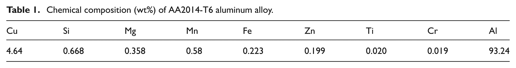
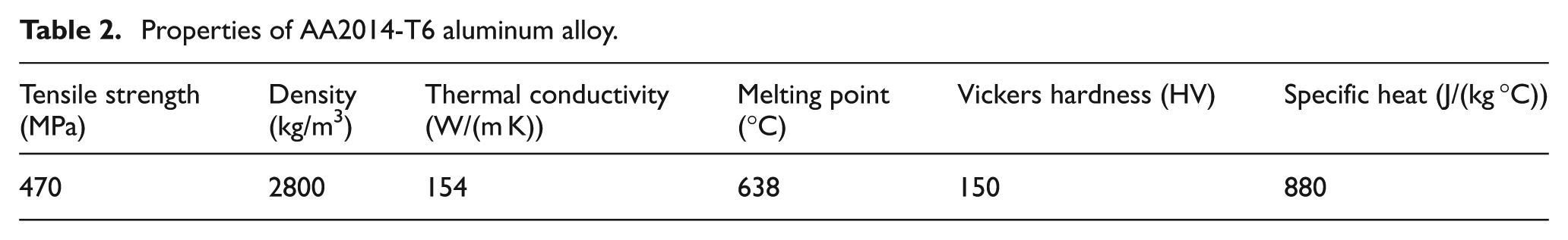
Friction stir welding was performed on a vertical milling machine with an indigenously designed fixture to hold the workpiece at the time of the experiments. The chemical composition and mechanical properties of the workpiece are presented in Tables 1 and 2, respectively. The plates used for welding were 300 mm × 50 mm × 5 mm in dimensions. The tool was made of high-speed steel with 17-mm shoulder diameter and a threaded taper tool pin having 5-mm mean diameter and 4.6-mm height. The pin used for experimentation was having 0.8-mm pitch. A zero tilt angle was selected in this work to simplify the experimental procedure. Penetration depth of 0.3 mm was applied to the welding tool while experimentation. The temperature data for immersed and air friction stir welding were collected using K-type thermocouples, and Agilent makes data logger. K-type thermocouples of 1.5-mm diameter were inserted in the mid-thickness on advancing side (AS) at a distance of 6, 8, 11 and 14 mm away from the joint line for measuring the temperature distribution during the welding process, and the layout of the same is shown in Figure 1. The welding speed of the tool was varied in the range of 80–125 mm/min at a constant rotational speed of 1000 r/min.
Chemical composition (wt%) of AA2014-T6 aluminum alloy.
Properties of AA2014-T6 aluminum alloy.
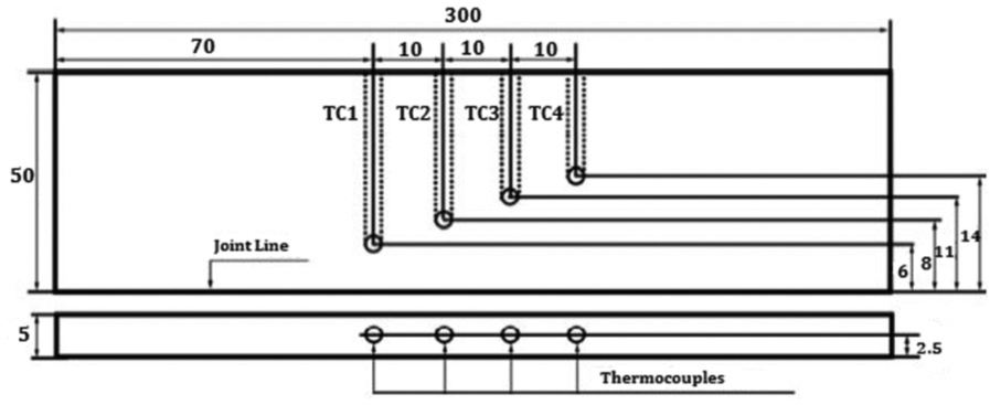
Thermocouple placement in the weld plate in air and immersed friction stir welding.
After welding, the samples were cross-sectioned perpendicular to the welding direction using an abrasive water jet for microstructural analysis and mechanical properties. The cross-sections of the metallographic samples for optical microscopy were polished to a mirror finish with a diamond paste. The samples were etched with Keller’s reagent. The etched specimens were rinsed in water and then blow dried and observed using optical microscopy. Vickers microhardness was measured under a load of 9.81 N for a dwell time of 10 s. All tensile tests were carried in accordance to ASTM E8M-04 guidelines. Tensile properties of each joint were evaluated through an average of three tensile specimens cut from the same joint. The fracture feature of the sample was evaluated by scanning electron microscopy (SEM) to study the fracture behavior after the tensile strength test. X-ray diffraction (XRD) analysis was also performed to know the type of precipitate formed during welding. To prepare transmission electron microscopy (TEM) samples, first, slight polishing was done on the processed surface to remove the onion rings. The samples were then mechanically polished on the unprocessed side (bottom side) until the thickness was reduced to 1 mm. Disk having 3-mm diameter was punched from the center position of the thin foils for the TEM specimens. The electron transparent thin sections were prepared through double jet electro-polishing using a solution of 30% nitric acid in methanol.
Results and discussion
Temperature profiles obtained using different welding speeds for air and immersed friction stir welding are shown in Figures 2 and 3, respectively. It is observed that as the welding speed increases, there is a considerable decrease in peak temperature (6 mm away from weld line) of welded joint. By increasing the welding speed from 80 to 125 mm/min, the peak temperature is decreased by 55 °C and 60 °C for air and immersed friction stir welding, respectively. The cooling rate used for the analysis is defined as ratio of ΔT/Δt, where ΔT is the temperature difference between peak temperature and temperature after 7 s of the peak and Δt is time difference, that is, 7 s. The cooling rate obtained for various welding speeds 80, 100 and 125 mm/min are 1.77 °C/s, 2.24 °C/s and 2.61 °C/s for air friction stir welding, respectively, and are 10.17 °C/s, 11.74 °C/s and 12.11 °C/s for immersed friction stir welding, respectively. It is concluded that at lower welding speed, the heat generation rate is more, and the weld joint at lower welding speed experiences heat for a longer duration which results in a lower cooling rate. While increased welding speed results in reduced heat generation and increases the cooling rate. Thus, the cooling rate is inversely proportional to welding speed. The higher cooling rate is observed in immersed friction stir welding compared to air friction stir welding, which reflects the positive cooling effect of water, and the higher cooling rate provides improved mechanical properties of the welded joint.
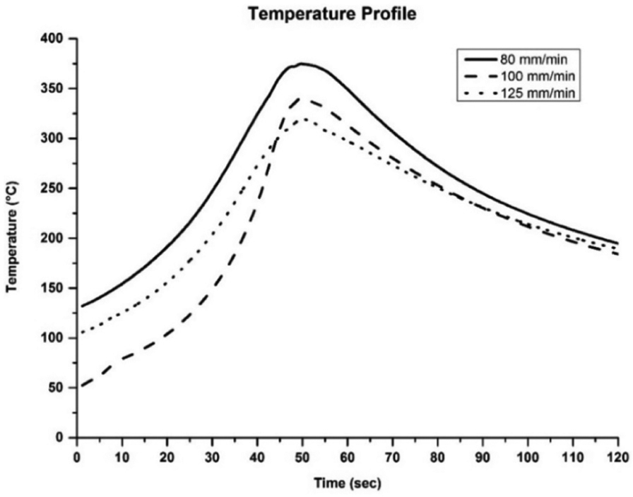
Temperature profile under different welding speeds for air friction stir welding.
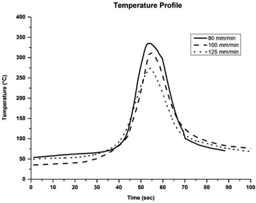
Temperature profile under different welding speeds for immersed friction stir welding.
Macrostructure and microstructure evaluation
Macrostructures of air and immersed friction stir welding joints prepared using different welding speeds are shown in Figure 4. Dynamically recrystallized grains are observed in the NZ of both air and immersed friction stir welding joints. This may be due to recrystallization taking place in intense temperature and subsequent plastic deformation. In case of immersed friction stir welding, clear boundaries between NZ and TMAZ are visible on AS because of more flow of the plastically deformed material on the advancing side compared with the retreating side. The boundary lines between NZ and TMAZ are not clearly visible from the microstructure of air friction stir welding joints. This is because of higher heat generation in air friction stir welding. The size of NZ is also small in immersed friction stir welding specimens compared to air friction stir welding specimens. This is due to the enhanced heat transfer rate of the welded plate immersed in the water. At lower welding speed, defect is seen at the bottom of specimens welded in immersed condition. The defect is produced owing to the higher heat generation, which leads to improper material flow in the NZ. Higher heat generation resulted in incomplete filling at the pin region due to higher movement of semi-solid aluminum. It also leads to enhanced formation of the flash and resulted into defects in the pin region of the weld bead. At the welding speed of 100 mm/min, an appropriate material flow occurs and provides good stirring action due to the reduction in heat input in the weld joint in immersed condition. Furthermore, at a welding speed of 125 mm/min, the defect occurs due to very less heat input, which reduces the material movement and material consolidation in the pin region. The material is not filled up densely in the NZ in a low heat input condition, which also forms the defects. In air friction stir welding, a sound joint without any defect is observed at higher welding speed of 125 mm/min as shown in Figure 4. This may be due to the reduced heat input at a higher welding speed of 125 mm/min. It is noticed from macrostructure of air friction stir welding specimens that at higher welding speed, proper joint is achieved; whereas, lower welding speed generates voids and defects in NZ. This also indicates that for a sound weld, lower welding speed should be preferred for immersed friction stir welding while relatively higher welding speed should be preferred for air friction stir welding.
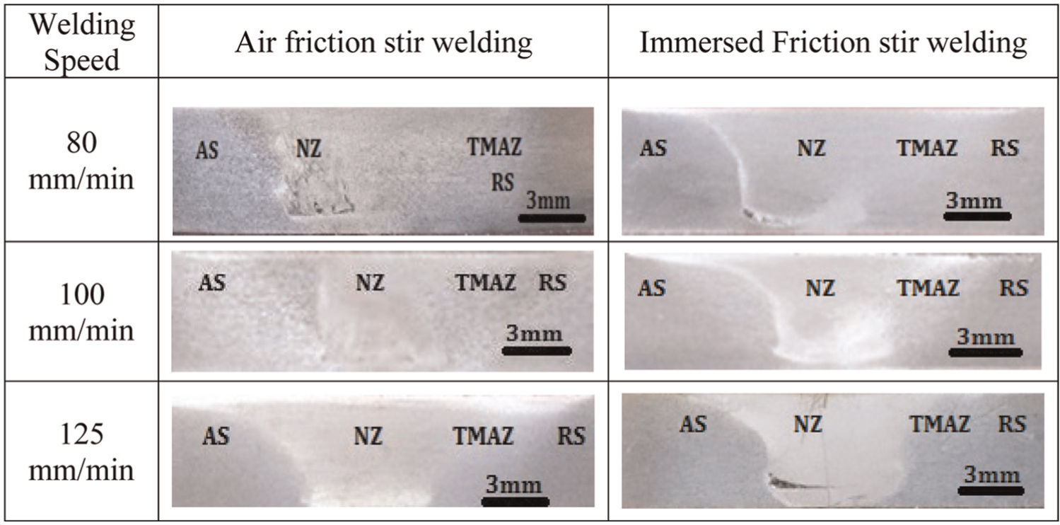
Macrostructure of a joint welded at different welding speeds and constant rotational speed of 1000 r/min in air and immersed conditions.
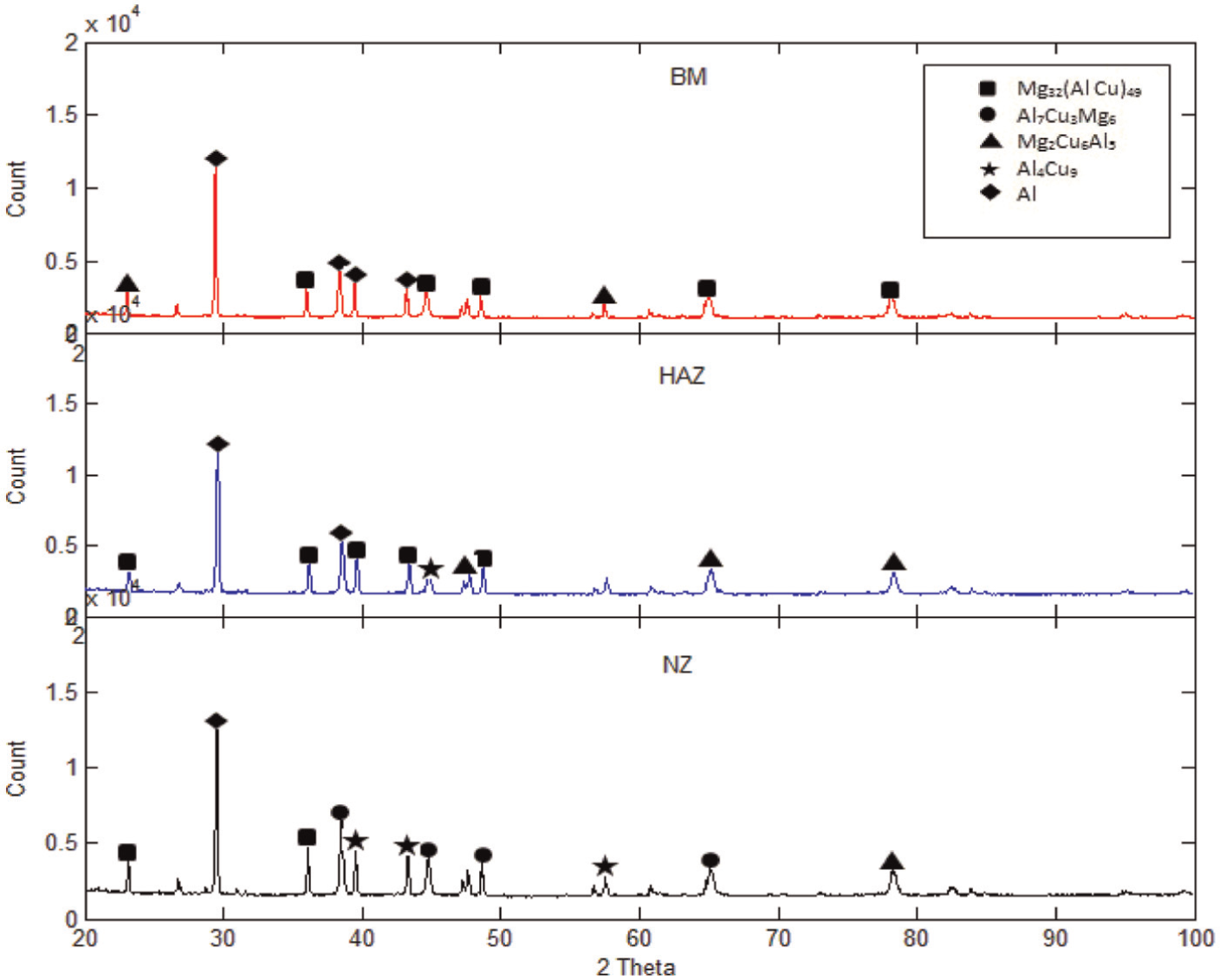
Microstructures of NZ/TMAZ interface of the specimen welded with 100 mm/min welding speed and 1000 r/min rotational speed in air and immersed conditions are shown in Figure 5. It is observed from the microstructure that NZ to TMAZ transition is very sharp in immersed condition in comparison to air friction stir welding. This sharp transition is due to the higher cooling rate of immersed friction stir welding. It is also noted that the grain size of immersed friction stir welding specimen at NZ is smaller than the air friction stir welding. Grains in HAZ are characterized with long elongated grains compared to base metal grains in both the conditions. Recrystallized grains observed in TMAZ of both air and immersed friction stir welding are larger than the grains formed in NZ. Well-accepted sequence of transformation for the Al-Cu series aluminum alloy is supersaturated solid solution—Guinier–Preston zone—metastable θ″ phase—metastable θ′ phase—stable θ phase. The transformation temperature of metastable phases in Al-Cu alloys is shown in Figure 6. Peak temperatures measured with the help of embedded thermocouples close to the NZ are 374 °C, 340 °C and 321 °C for air friction stir welding and 335 °C, 313 °C and 275 °C for immersed friction stir welding with welding speed of 80, 100 and 125 mm/min, respectively. As base metal is unaffected by temperature, optical microscopy of base metal revealed that fine and elongated grains are present with precipitates of Mg32(Al Cu)49 as shown in Figure 7. XRD analysis of base metal shown in Figure 7 revealed that precipitates are a mixture of aluminum, magnesium and copper as Mg32(Al Cu)49, known for its strengthening qualities, have a major contribution which provides the high strength to base metal. Coarsening of metastable precipitates has taken place in HAZ of both air and immersed friction stir welding joints. This is because of the zone has experienced temperature in the range of 250 °C–350 °C. XRD analysis of HAZ shows softening precipitates Mg2Cu6Al5 and strengthening precipitates Mg32(Al Cu)49 in both air and immersed friction stir welding. Coarsening and the dissolution of some strengthening precipitates are observed in the HAZ as HAZ temperature reaches to 250 °C. This produces the strengthening precipitates free zones in HAZ region and reduces the strength in both air and immersed friction stir welding. Same kind of observations had been made by other researchers.2–5
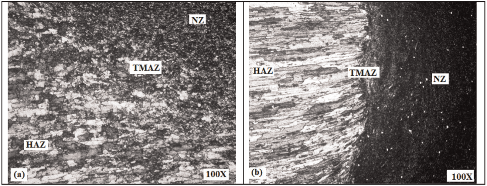
Microstructure of NZ/TMAZ interface at 100 mm/min and 1000 r/min: (a) air friction stir welding and (b) immersed friction stir welding.
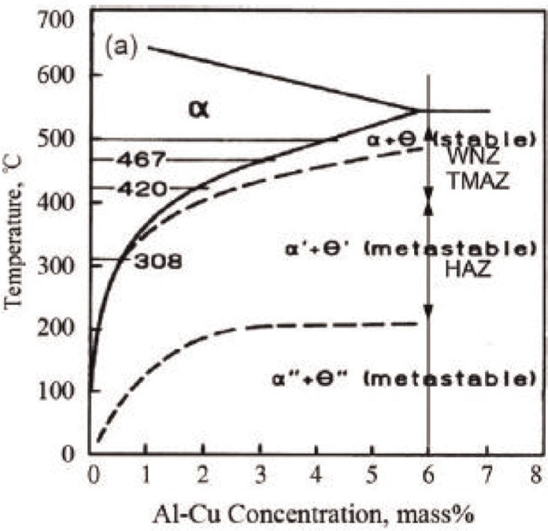
Precipitates’ transformation diagram of Al-Cu alloys. 24
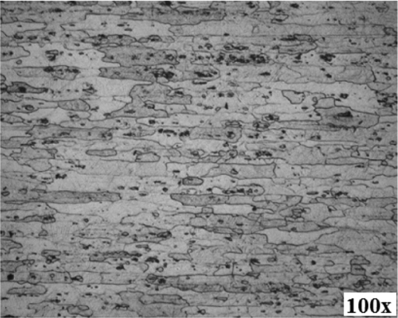
Microstructure of base metal AA2014-T6.
Influence of welding speed on generation of the precipitates was studied using XRD analysis. XRD analysis of friction stir welding joints prepared using both air and immersed conditions are shown in Figures 8–11. Photographs of XRD analysis revealed the presence of precipitates like Mg32(Al Cu)49, Al7Cu3Mg6, Mg2Cu6Al5 and Al4Cu9 in various zones. It is found that with an increase in welding speed, dissolution of strengthening precipitates is reduced in both air and immersed friction stir welding. It is also observed from Figures 8 and 10 that dissolution of strengthening precipitates Mg32(Al Cu)49 is more for welding speed of 100 mm/min compared to welding speed of 125 mm/min in air friction stir welding. It is also found from the XRD analysis that HAZ is the weakest zone among all zones as it is found with minimum peaks of strengthening precipitates. XRD analysis for immersed friction stir welding shows that more strengthening precipitates of Al7Cu3Mg6 and Mg32(Al Cu)49 are present in the HAZ and NZ. Workpiece is exposed to high temperature for the smaller duration in case of immersed friction stir welding compared to air friction stir welding, which prevents the dissolution of strengthening precipitates. With an increase in welding speed, reduction in the dissolution of precipitates is observed. This is due to a reduction in the peak temperature experienced during welding with an increase welding speed in both air and immersed friction stir welding.
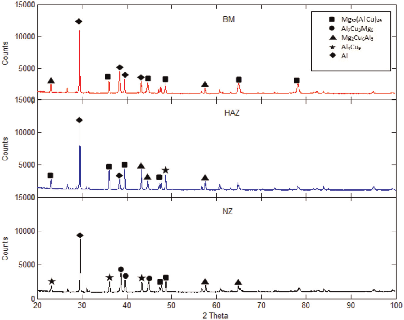
XRD analysis for air friction stir welding at rotational speed of 1000 r/min, welding speed of 100 mm/min and shoulder diameter of 17 mm.
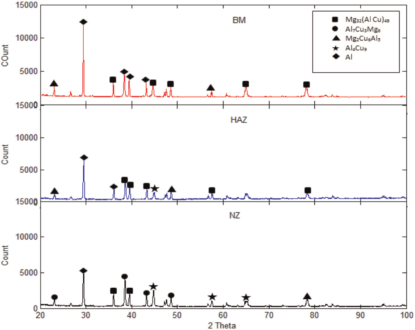
XRD analysis for immersed friction stir welding at rotational speed of 1000 r/min, welding speed of 100 mm/min and shoulder diameter of 17 mm.
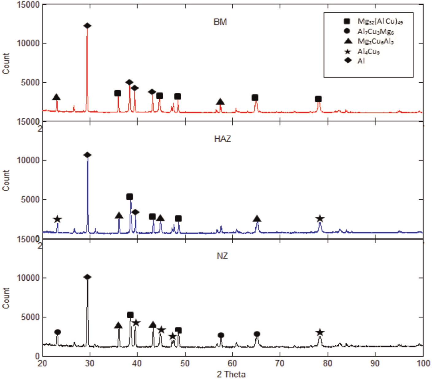
XRD analysis for air friction stir welding at rotational speed of 1000 r/min, welding speed of 125 mm/min and shoulder diameter of 17 mm.
XRD analysis for immersed friction stir welding at rotational speed of 1000 r/min, welding speed of 125 mm/min and shoulder diameter of 17 mm.
The TEM micrograph of the base metal is shown in Figure 12(a). It reveals the presence of various strengthening precipitates. Energy Dispersive Spectroscopy (EDS) spectrum obtained from one of the second-phase particles is shown in Figure 12(b), which indicates that the second-phase particle is composed of Al and Cu (equilibrium θ (Al2Cu) phase). The XRD analysis also revealed that base metal (BM) has higher strength due to Al2Cu and other precipitates present. It is also observed in Figure 12(c) and (d) that in the NZ and TMAZ, precipitates have coarsened and some precipitates dissolved into the solution. This is responsible for the reduction of joint strength in air friction stir welding. TEM micrograph of NZ and TMAZ of immersed friction stir welding is shown in Figure 12(e) and (f). It also shows that precipitates are dissolved, but the level of dissolution is lower than air friction stir welding; hence, higher strength of the joint is obtained in the immersed friction stir welding condition. NZ experiences higher temperature than TMAZ during friction stir welding which is also responsible for the dissolution of strengthening precipitates, and due to this, TMAZ showed higher density of dislocations.
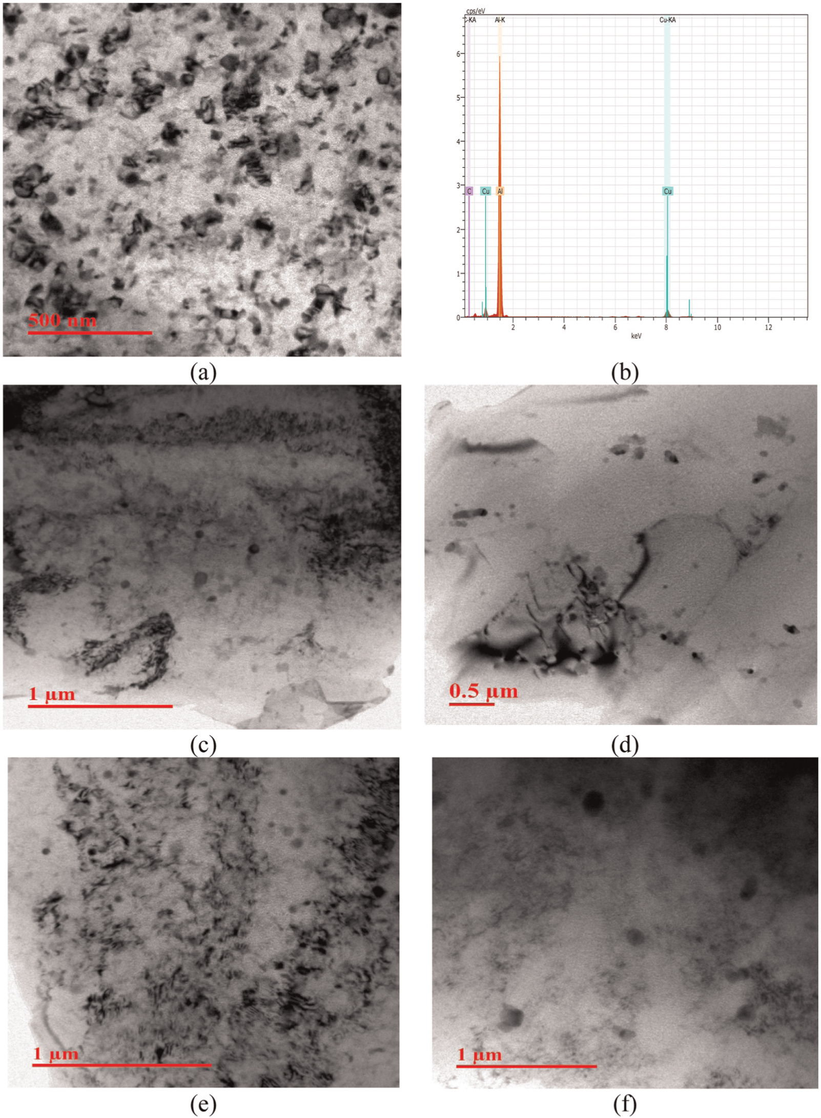
(a) TEM micrograph of base metal, (b) EDS spectrum obtained on one of the spherical particles, (c) TEM micrograph of TMAZ in air friction stir welding, (d) TEM micrograph of NZ in air friction stir welding, (e) TEM micrograph of TMAZ in immersed friction stir welding and (f) TEM micrograph of NZ in immersed friction stir welding.
Microstructure of NZ of various specimens welded at different welding speeds in air and immersed condition is shown in Figure 13. NZ found to have fine equiaxed recrystallized grains due to intense plastic deformation and friction from rotating tool. Microporosities were observed in all the joints. This is due to incomplete filling of the material in the pin region. In this research work, zero tilt angle tool was used. Less consolidation of material in the pin region also due to zero tilt angel of the rotating tool. At a higher welding speed, plasticized material may be cooler and could not easily forged by the shoulder, resulting in the defects in the joint. With an increase in welding speed resulted in a decrease in both the degree of material deformation and heat input during friction stir welding which resulted into increased levels of microsize porosities in the NZ. However, specimens were failed at TMAZ and HAZ interface during tensile strength testing so the presence of microsize porosities in NZ does not affect the mechanical properties of the joint. Lower welding speed tends to produce porosity and higher grain size as compared to higher welding speed in air friction stir welding. This is due to higher heat input in the welded joint at lower welding speed. Also, due to high peak temperature and plastic deformation at lower welding speed, larger grains are observed in NZ and grain size is found to decrease with increase in welding speed both in air and immersed friction stir welding. Immersed friction stir welding joint is found to have smaller grain size compared to air friction stir welding joint due to lower temperature experienced during welding. Moreover, NZ of immersed friction stir welding is found to have lower porosity compared to air friction stir welding and the same is visible in Figure 13. It is concluded that higher welding speed should be selected in case of air friction stir welding compared to immerse friction stir welding of AA2014-T6 for obtaining joint with minimum porosity and defects.
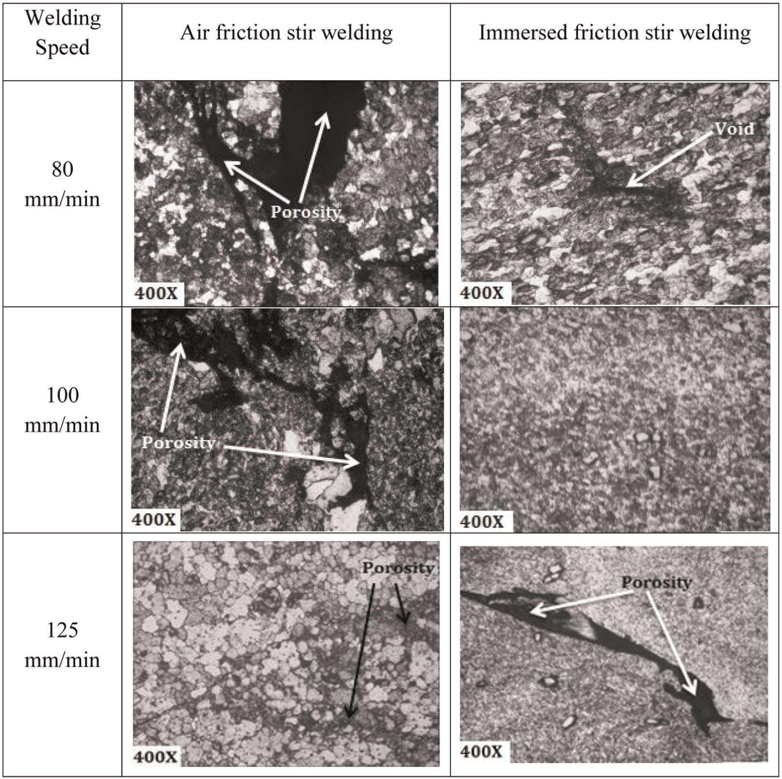
Microstructure of the NZ of friction stir welding AA2014-T6 at different welding speeds and constant rotational speed of 1000 r/min.
Microhardness distribution of friction stir welding joints
Figures 14 and 15 shows the distribution of microhardness in welded joints at different welding speeds for both air and immersed friction stir welding respectively. Microhardness test was performed at a mid-thickness of welded joint cut perpendicular to the direction of the tool travel. Microhardness profile displays a “W”-type shape and the hardness curve is asymmetrical with respect to the weld centerline. A similar profile was observed by Liu et al. 10 for friction stir welding of 2xxx series aluminum alloy. This is because of the non-uniformity of both temperature and plastic material flow on both the sides of weld centre.26,27 Results revealed that soft regions like NZ and TMAZ have lower hardness compared to base metal. The hardness value of the NZ is higher than that of TMAZ, due to its fine equiaxed grain structure and re-precipitation of the strengthening precipitations. Friction stir welding creates the softened region in weld joint compared to the base metal. Such a softening is caused by coarsening or dissolution of strengthening precipitates during the thermal cycle of friction stir welding. Hardness profile for air friction stir welding joint was prepared at welding speed of 100 mm/min. It showed that base metal has hardness value of 147 HV, which has decreased to 118 HV in TMAZ. This is due to more dissolution of strengthening precipitates in TMAZ. An increase in hardness from 118 to 127 HV has been observed in NZ due to generation of new strengthening precipitates Al7Cu3Mg6. A similar trend is observed in case of immersed friction stir welding, where hardness is found to decrease from 147 to 130 HV in TMAZ and after that again increased to 139 HV in NZ. Hardness value found to be increased due to increase in welding speed. From Figures 14 and 15, it can be noticed that with an increase in welding speed from 100 mm/min to 125 mm/min, hardness in NZ is increased from 127 to 131 HV in air friction stir welding. In immersed friction stir welding, an increment in hardness is found to be 139–141 HV for similar weld condition. It is noted that value of hardness in NZ is higher for immersed friction stir welding compared to air friction stir welding. An increased value of hardness in NZ of immersed friction stir welding joint is due to proper mixing of material with sufficient heat, regular material flow and water prevents further dissolution of the precipitates. The cooling effect of water is the main factor for the formation of better weld joints. The presence of water reduces recrystallization temperature and in turn creates new precipitates which also retain precipitates in NZ.
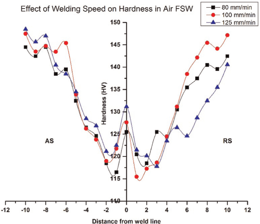
Effect of welding speed on hardness for air friction stir welding at 1000 r/min rotational speed.
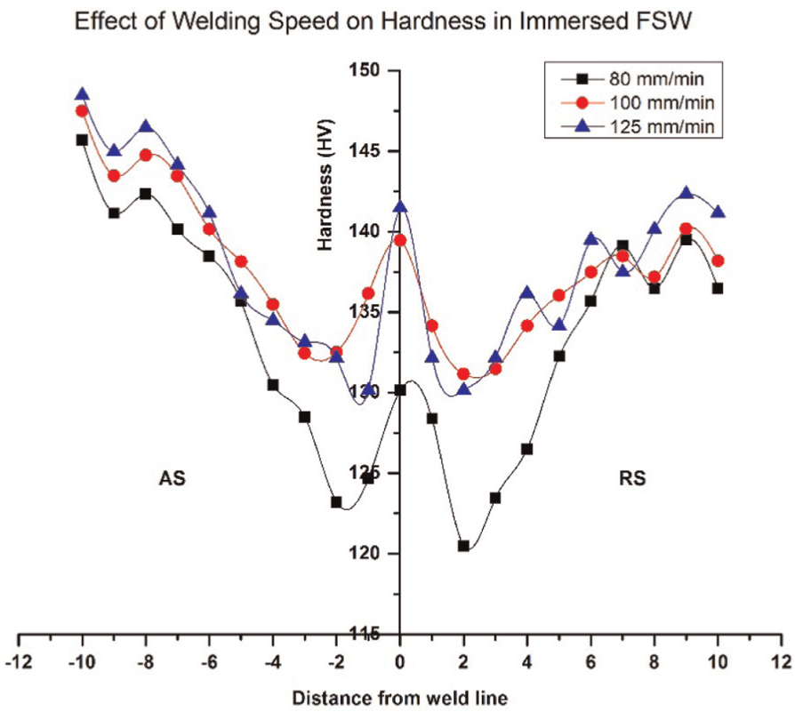
Effect of welding speed on hardness for immersed friction stir welding at 1000 r/min rotational speed.
Tensile properties and fractography of welded joints
Tensile test for air friction stir welding joints revealed that an increase in welding speed from 80 to 125 mm/min results in an increase in tensile strength from 245 to 285 MPa as shown in Figure 16. Tensile failure has occurred either on the advancing side or on the retreating side, depending on how the flow of material occurred and which side of the weld is under higher temperature evolution. It is observed that the fracture has taken place at TMAZ/NZ on advancing side of the joint in air friction stir welding. This may be due to the sharp interface present between TMAZ and NZ of air friction stir welding joint. The maximum population of dimples is observed at a welding speed of 125 mm/min, which results in maximum tensile strength due to the proper stirring action of material as well as less dissolution of strengthening precipitates. Lower welding speed results in higher heat input in the welded joint, which leads to improper material flow and reduces the strength. For immersed friction stir welding, with an increase in welding speed from 80 to 100 mm/min, tensile strength of the joint is increased from 283 to 332 MPa. Further increase in welding speed to 125 mm/min has shown a decrease in tensile strength to 295 MPa. Lower welding speed produces the defects and improper material flow, and the same are responsible for the lower joint strength. An increased dissolution of strengthening precipitates is being observed at a welding speed of 100 mm/min, which results in reduction of tensile strength. In immersed condition, strength improvement is observed due to non-dissolution of strengthening precipitates at NZ and TMAZ compared with air friction stir welding. Due to this, immersed friction stir welding joints showed higher strength than air friction stir welding joints. Also, the maximum tensile strength of the immersed friction stir welding joints is higher than that of the air friction stir welding joints. Maximum tensile strength obtained in an immersed friction stir welding joint is around 17% higher than maximum strength obtained by air friction stir welding joint. Immersed friction stir welding is the technique by which tensile strength of the joint can be improved.
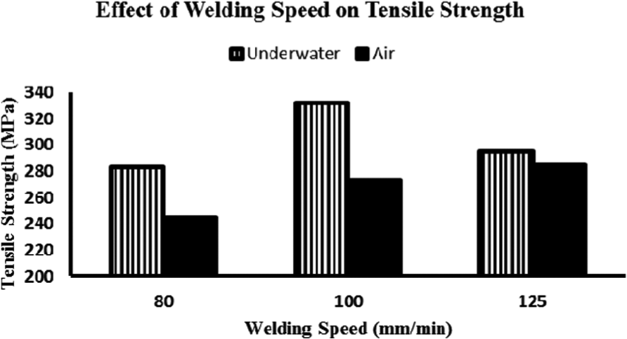
Effect of welding speed on tensile strength (1000 r/min rotation speed).
The tensile fracture surface provides information about microstructure features which affect the tensile strength and ductility of joint prepared using AA2014-T6. SEM examination of the fractured surfaces revealed many dimples having different sizes and shapes. The microfracture surfaces of specimens after tensile testing of welded joints produced by air and immersed friction stir welding are shown in Figure 17. Deep holes, small dimples and tear ridge–type dimples are visible in weld joint prepared using air friction stir welding, while shallow hole–type large dimples are witnessed as the fracture features in the immersed friction stir welding joint after tensile testing. Second-phase particles are present on the fractured surface of immersed friction stir welding joints. The presence of second-phase particles is responsible for higher tensile strength and a reduction in the ductility. Effect of welding speed on fractured surface is also studied. With an increase in welding speed, the population of dimples increases and in turn reduces the ductility of a fractured surface in both air and immersed friction stir welding.
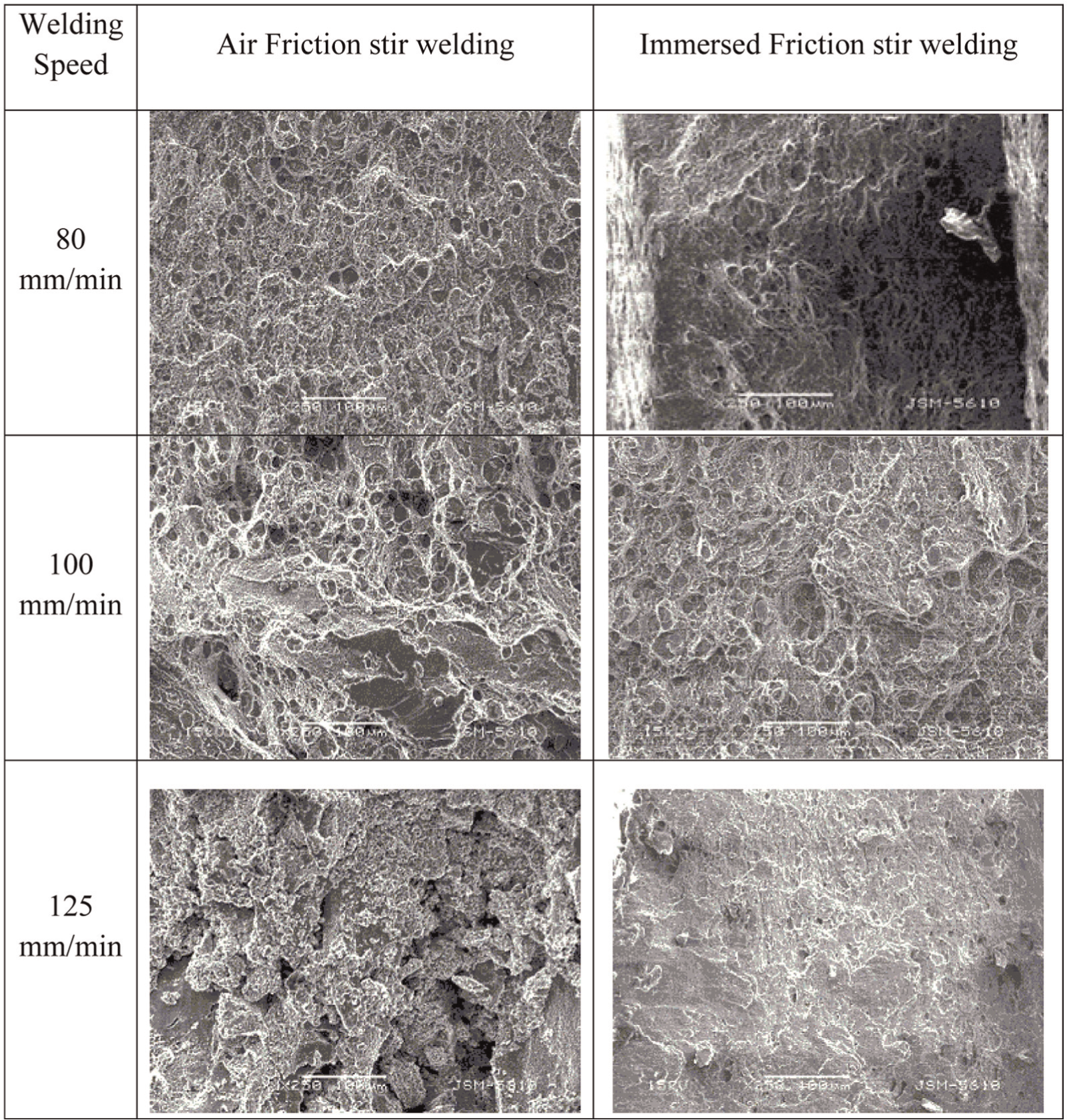
SEM fractography of tensile specimen at different welding speeds and constant rotational speed of 1000 r/min.
Conclusion
Friction stir welding joints were produced in air and immersed water conditions using various welding speeds to study the effect on microstructure and mechanical properties. Following are the conclusions drawn from the study:
With an increase in welding speed, heat input reduces, which also reduces the dissolution of strengthening precipitates and hence increases tensile strength of the air friction stir welding joint. While in immersed friction stir welding, at lower welding speed as well as higher welding speed, tensile strength reduces due to occurrence of voids. Microstructure result shows that grain size is found to decrease with an increase in welding speed due to less heat input in both air and immersed friction stir welding.
XRD analysis indicates that dissolution of strengthening precipitates increases in NZ and TMAZ with an increase in temperature, which may result in a decrease in mechanical properties of the welded joint. Also the microhardness distribution for the various joints shows the lowest hardness region in TMAZ in both air and immersed friction stir welding. The strength of NZ is higher than the TMAZ due to grain refinement by the rotating pin.
In air friction stir welding, NZ experienced temperature nearer to 400 °C, which forces metastable precipitates to dissolve. However, in immersed friction stir welding, maximum temperature is less than 400 °C and time for which material remains at higher temperature is also less compared to air friction stir welding. Hence, less dissolution of the strengthening precipitates, which increases tensile strength and microhardness of joints.
Maximum tensile strength of 285 and 332 MPa have been obtained at welding speeds 80 mm/min in air and 100 mm/min in immersed friction stir welding, respectively, for constant rotational speed of 1000 r/min. Maximum tensile strength obtained in an immersed friction stir welding joint is around 17% higher than the maximum tensile strength obtained by air friction stir welding. With an increase in welding speed, the population of dimples increases and in turn reduces the ductility of a fractured surface both in air and immersed friction stir welding.
Footnotes
Declaration of conflicting interests
The author(s) declared no potential conflicts of interest with respect to the research, authorship and/or publication of this article.
Funding
The author(s) disclosed receipt of the following financial support for the research, authorship, and/or publication of this article: This study was financially supported by the Science and Engineering Research Board of Department of Science and Technology, New Delhi, India, sanctioned through letter SR/S3/MERC/0108/2012.