
Abstract
Abbe error is the inherent systematic error in linear displacement measurement due to the measuring axis being out of line with the moving axis. The resulting gap is called the Abbe offset, which will multiply the angular pitch error of the moving stage to become the positioning error of the linear stage along the moving axis. Analogous to the Abbe principle, in the rotary stage, the rotary encoder is used to detect the worktable’s rotational angle. The encoder is normally mounted at a distance from the bearing. This distance can be also regarded as Abbe offset. Due to the inherent tilt and radial motions of the axis of rotation, the encoder’s rotating component, that is, the circular grating, would result in a lateral displacement relative to its sensing head that is fixed inside the stage housing. The actual measured angle is, therefore, different from the commanded angle, causing the angular positioning error of the rotary stage in machine tools and open-loop controlled system. In this article, the angular positioning error of the rotary stage caused by the tilt motion error and radial motion error of the spindle, the offset and the size of encoder is analyzed and experimentally verified.
Introduction
In 1890, Ernst Abbe 1 proposed a measuring principle for the design of dimensional measuring instruments which was translated into English as: “The measuring apparatus is to be arranged in such a way that the distance to be measured is a straight line extension of the graduation used as a scale.” Bryan 2 recognized this so-called Abbe principle as being the first principle of machine tool design and dimensional metrology and extended the concept to the straightness measurement to propose the Bryan principle as “The effective point of a straightness measuring system should lie along a line which is perpendicular to the direction of slideway travel and passes the functional point whose straightness is to be measured. If it is not possible, either the slideways that transfer the straightness must be free of angular motion or angular motion data must be used to calculate the consequences of the offset.” Zhang 3 later modified the Abbe principle with a new definition: “The line connecting the reference point and sensing point should lie in the sensitive direction.” He applied the principle to all cases of dimensional measurements, including one-dimensional (1D), two-dimensional (2D) and three-dimensional (3D) measurements; straightness and roundness measurements; and run-out measurements. Jaeger et al. 4 applied the Abbe principle in 3D design of an ultra-high-precision nanopositioning and nanomeasuring machines. Today, engineers and researchers worldwide use both the Abbe and Bryan principles as guidelines in the design of linear motion machines, such as linear positioning stages, machine tools and coordinate measuring machines (CMMs).5–8
In addition to linear machines, modern industry uses a variety of rotary indexing devices, such as rotary stages, C-axis in machine tools, CMMs and robots. The rotational accuracy of the rotary stage is as important as the positional accuracy of the linear stage. Due to design, manufacturing and assembly errors, both stages have inherent systematic geometric errors in 6 degrees of freedom (6-DOF), including three translational errors and three angular errors, for which definitions and test codes are specified in ISO230-1:2012, 9 ISO 230-7:2006 10 and ASME B89.3.4-2010. 11 Methods to determine the accuracy and repeatability of positioning of numerically controlled axes are specified in ISO 230-2:2014. 12 Consequently, accurately measuring the 6-DOF errors of the rotary stage is as important as measuring the linear stage. It is known that longer testing times result in increased environmental influence. Therefore, many previous studies have proposed various multi-degree-of-freedom (MDOF) measuring methods for an axis of rotation (for spindles) and a rotary table,13–25 but they all investigated the error separation techniques among combined errors. The rotary angular positioning error caused by other effective errors, such as tilt and radial errors, has little been investigated.
The displacement sensor, such as linear scale or rotary encoder, of most linear stages is mounted along a fixed reference axis below the moving table. This creates an Abbe offset and, according to the Abbe principle, the positioning error along any functional axis other than the reference axis is mainly caused by the angular pitch error multiplied by the Abbe offset. Similar to the Abbe principle applied to the linear stage, in the rotary stage, the rotary encoder is commonly used as a reference sensor and is normally mounted at a distance from the bearing that is below the functional rotating plane. Due to inherent tilt and radial motions of the axis of rotation, the rotating component of the encoder, that is, the circular grating, would result in a lateral shift relative to its sensing head that is fixed inside the stage housing. The actual measured angle will, therefore, be different from the commanded angle, causing angular positioning errors in the rotary stage in machine tools and open-loop controlled system. This phenomenon has not been investigated in detail. In this article, the angular positioning error of the rotary stage caused by the tilt motion error and radial motion error of the spindle, the offset and the size of encoder is analyzed and experimentally verified.
Geometric errors of the rotary stage
Rotary stages are also called rotary tables or rotary positioners in industry. In this article, the whole structure is called a rotary stage, and the top moving table is called a rotary table. The rotary stage has a rotational axis represented by the spindle axis. Similar to the existing 6-DOF errors in the linear stage, design, manufacturing and assembly errors produce 6-DOF geometric errors in the rotary stage, including three translational and three rotational errors,9,10 as shown in Figure 1. 26 The translational errors can be separated into an axial motion error (δz) and two radial motion errors (δx and δy); the rotational errors can be separated into two tilt motion errors (εx and εy) and an angular positioning error (εz). Analogous to the Abbe principle that applies to induced positioning errors along the functional axis of a linear stage in the presence of angular motion errors, the angular positioning error of a rotary stage should be induced by other geometric errors as well. A detailed interpretation of this hypothesis is expressed in the following sections.
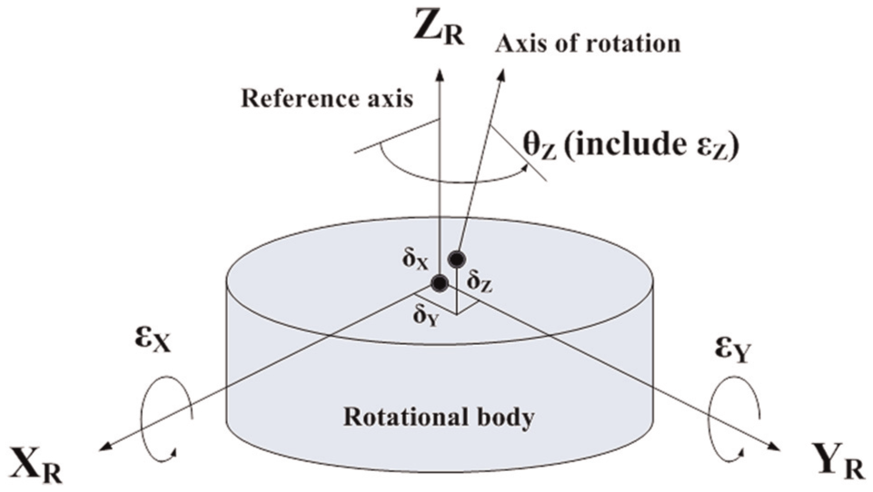
6-DOF error motions in the rotary stage presented by Slocum. 26
Analysis of the rotary angular positioning error
Common rotary stages have two types, namely, the worm-drive type and the direct-drive type. The main rotational body showing the radial motion error and tilt motion error is represented in Figure 2(a). For the worm-drive type, the shaft is rotated with the worm, and for the direct-drive type, the shaft is constrained by the bearing. The tilt and radial motions of the axis of rotation are assumed to occur at the intersection point of the shaft and the component that constrains the shaft. For detecting the angle of rotation, a rotary encoder is often used as the sensor mounted to the near end of the shaft, as shown in Figure 2(b), where the circular moving grating is coaxially connected to the shaft. The emitted light (light-emitting diode (LED)), secondary fixed grating and the photodetector (PD) of the encoder are fixed to the housing and are grouped as the sensor head. For clarity, the supported rotational bearing of the shaft is not shown here.
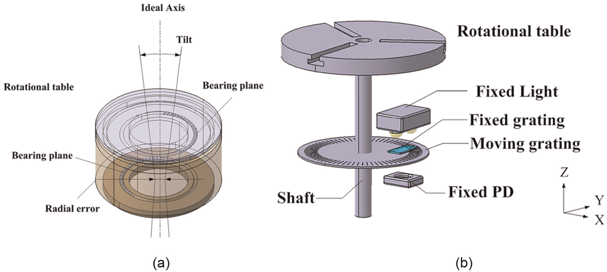
Structure of a rotary table: (a) main rotational body of direct-drive type and (b) with encoder.
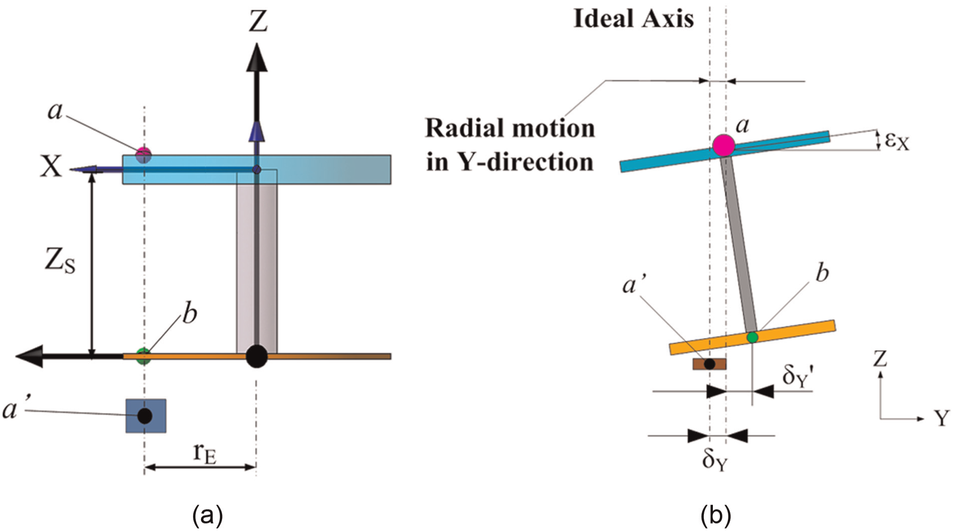
Due to experimental limitations, only the worm-drive rotary stage was investigated. To express the cause of the angular positioning error in terms of other effective geometric errors, a simplified relationship between the upper tilt-pivotal plane and the lower grating plane is shown in Figure 3(a). The tilt-pivotal plane is the plane of the worm. In this study, the moving grating is assumed to have no coupling errors. This figure also shows the ideal corresponding points of the upper worm plane (a) and the lower grating plane (b) without any geometric errors, and the current X-axis passes through point a on the worm plane. The index angle of point a is measured by the rotational angle of the grating at point b, and both are relative to the axis of rotation. The radial motion of the axis of rotation will cause all moving components, including the shaft, the worm, the circular grating and the top rotary table, to be simultaneously laterally shifted perpendicular to the axis of rotation. Just looking at the motion of the circular grating relative to the fixed components of the encoder, when the grating disk is shifted in the radial direction of the grating scale, the encoder will not read any angle change. However, if the grating disk is shifted to the tangential direction of the scale, as shown in Figure 3(b), the original point b on the circular grating will also be shifted and more scales will be read by the sensor head. Similarly, if the shaft is tilted around X-direction, it will induce the scale motion in the Y-direction with respect to the tilt center, as shown in Figure 3(c). Figure 4(a) shows the side view of the X-Z plane of Figure 3(a) in which point a′ indicates the fixed sensor head position, Zs is the offset of the grating plane from the tilt center and rE is the radius of the sensor head of the encoder, with points a and b being the same as in Figure 3. It can be seen from Figure 4(b) that, at any instantaneous rotational angle θ of the rotary stage, the radial error in the Y-direction (δy(θ)) and the tilt angle around the X-direction (εx) will both shift the scale disk in the tangential direction (Y) by a total distance of

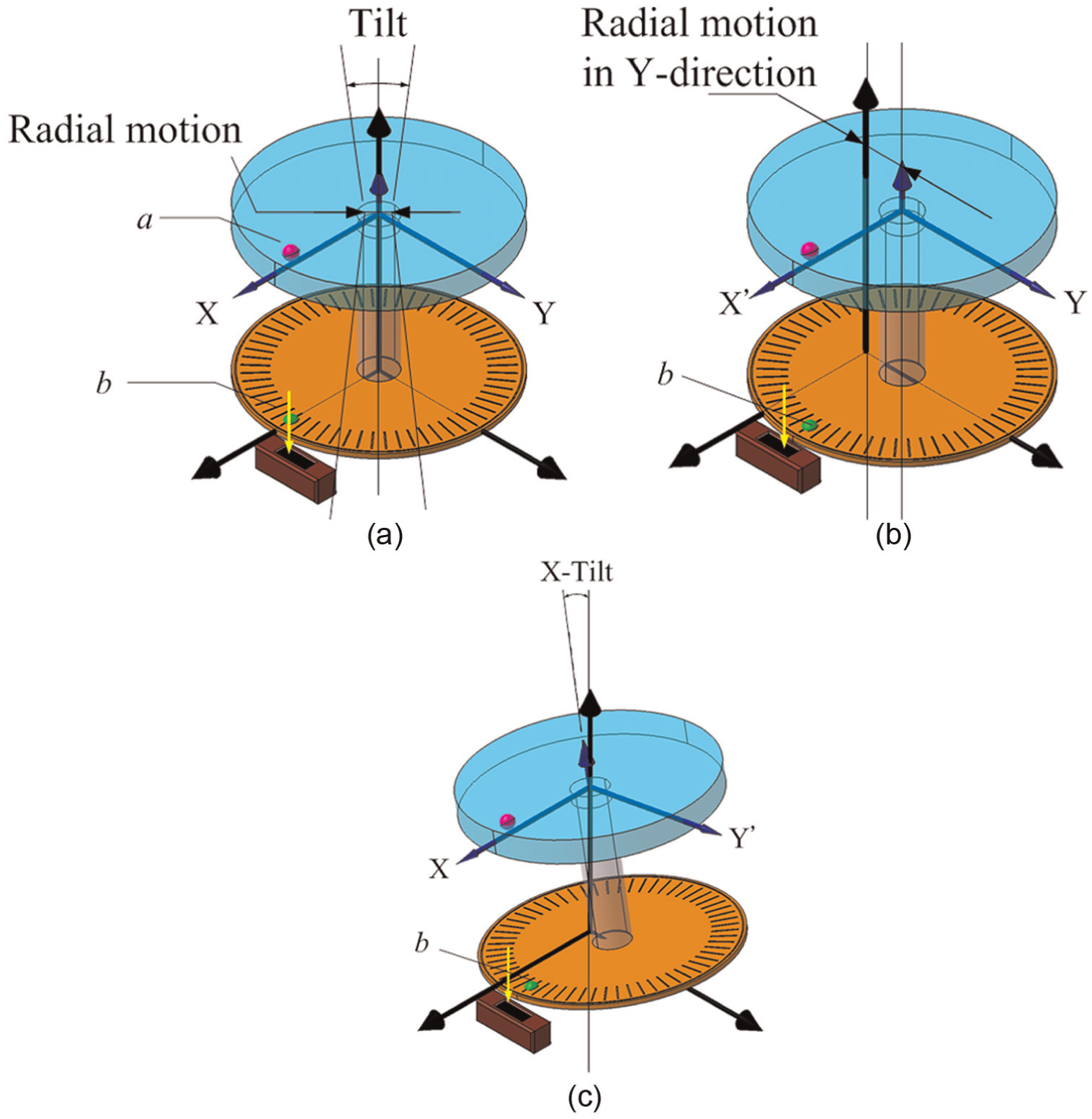
Shift of grating disk in the tangential direction: (a) at no error condition, (b) with radial error of the shaft in Y-direction and (c) with tilt of the shaft around X-direction.
2D view of the rotary table at (a) no error and (b) tilt and radial motions.
Figure 5 shows the top view of the grating plane. It is clearly seen that the total shift of the sensing point on the grating from the ideal point b to the actual point b′ will yield to the angular reading error of the encoder (εz), which can be expressed by
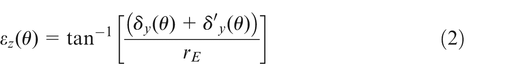
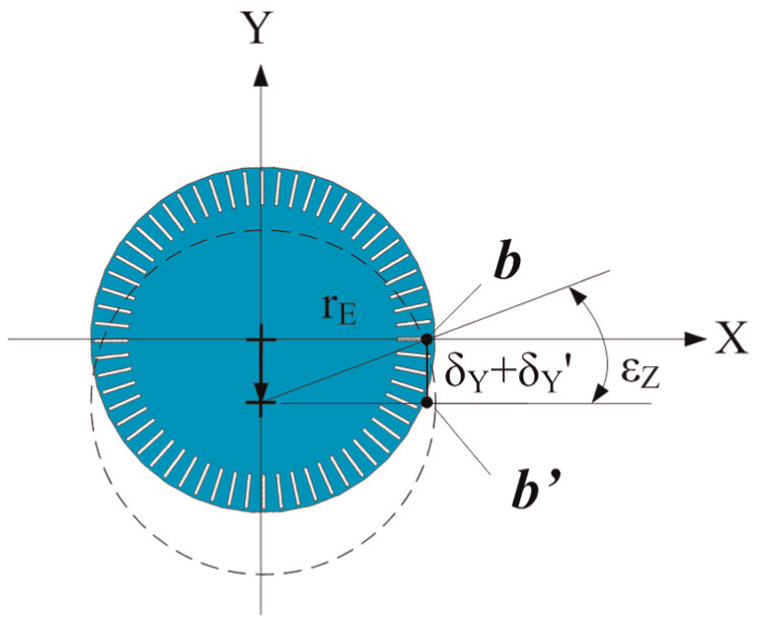
Angular positioning error induced by the tangential shift of the grating.
From equations (1) and (2), it is clearly seen that the angular positioning error is induced by the radial and tilt motions of the shaft shift in the tangential direction of the grating disk, the offset of the grating plane to the top table plane and the radius of sensor head. The offset and the sensor radius can be obtained from the stage design or can be measured if the stage assembly is opened carefully. The radial error, tilt error and angular positioning error are to be measured. Methods of measurement are discussed in the following section.
Geometric error measurements
Experiments were carried out to measure the rotary angular positioning error, the radial error and the tilt error on a modified worm-drive rotary table. ISO 230-7:2006 specifies the mounting of a precision test ball or a precision cylinder in the machine spindle, and mounting displacement sensors to the table of the machine, to measure tilt and radial motions of the spindle. However, the eccentricity of the ball or the cylinder to the axis of rotation must be minimized manually, which is prone to error. All other methods also measured the error motions of the top rotary table or the external spindle.13–25 The eccentricity and the tilt of the top table relative to the axis of rotation, that is, the inner spindle, were ignored. From equation (2), it can be estimated that even a very small radial motion of the table in the tangential direction of the grating disk will generate an obvious error of the grating, because the encoder size is normally small. Therefore, this study adopts different methods that can directly measure radial and tilt errors of the inner shaft of the rotary stage.
In the investigated worm-drive rotary stage (Parker Hannifin, model 200RT), the indexing angle is counted by commanded pulses of the stepping motor without using a rotary encoder, thus this stage was specifically modified by adding a rotational module consisting of a top table, a shaft and a rotary encoder (Canon M-1H), all coaxially fixed together, as schematically shown in Figure 6. The rotary stage was suspended by a supporting frame to allow for the installation of a rotary encoder under the shaft through a coupler. The top table and the shaft were made in one piece by turning so that the eccentricity error could be ignored. Two dial indicators with a resolution of 1 µm were used to measure the radial motion errors of the shaft and the top table at two selected points (L1 was 5 cm and L2 was 7 cm). These radial error measurements were effective only to the tangential direction of the grating, that is, the Y-direction in Figure 4(b). Let the upper point be the tilt center; two measured radial errors could separate tilt and radial errors by simple calculation. According to ISO 230-1:2012, 9 angular positioning error measurement can be done using either a precision optical polygon as the reference angle artifact with an autocollimator or a reference indexing table with an angular laser interferometer. Due to the lack of an expensive reference indexing table, this study adopted an autocollimator and a polygon to measure the angular positioning error. Figure 7 shows the experimental setup.
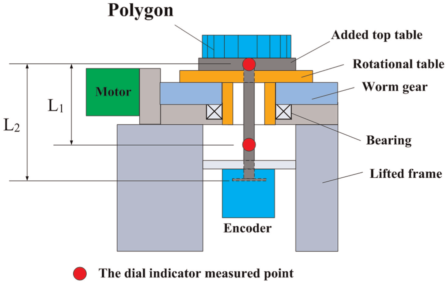
Tested rotary stage.
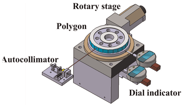
Experimental setup for angular positioning error measurement.
Results of measured tilt and radial errors
As shown in Figure 7, the measurement system could not directly measure the shift of the moving grating because it was sealed in the encoder. Therefore, only the radial errors in the Y-direction at two specified positions could be measured by two dial indicators denoted by δy(θ) and

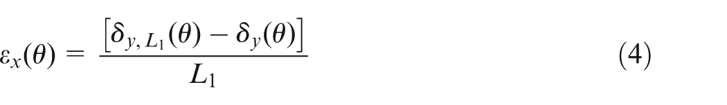

Relationship of the tangential shift of the moving grating and the errors measured by the dial indicators.
The last term in equation (5) represents
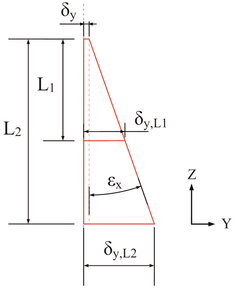
Figure 9 shows the combined plots of tilt and radial errors on the plane of the grating disk for a full rotation of the rotary stage. The tilt motion is only around the X-direction, that is, εx(θ), and radial motion is only in the Y-direction, that is, δy(θ).
Results of the tilt motion around X-direction and the radial motion in Y-direction.
Results of measured angular positioning error
The system setup using an autocollimator and a 24-sided polygon is shown in Figure 8. The autocollimator was self-made. 27 This autocollimator was calibrated by the HP5529A angular interferometer, and the residual error is less than 1 arcsec in the measuring range of ±150 arcsec. The polygon was calibrated by the method using two autocollimators set up to give reflections from adjacent polygon faces. 28
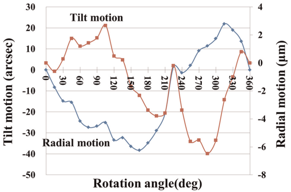
The rotational angle of the rotary stage was controlled by the stepping motor in open loop, which indicates the angle is different from the encoder and the autocollimator. At each step, the encoder reading and the autocollimator reading were simultaneously recorded. The difference of these two readings after a complete cycle was calculated to obtain the encoder’s angular positioning error. Results are shown in Figure 10. There are 12th harmonic angular positioning errors in the results measured by both autocollimator and encoder. They are probably caused by worm transmission with open-loop control.
Results of angular positioning error measurement.
Experimental verification
From theoretical analysis of equation (2), angular positioning errors of the rotary stage can be predicted if the tilt and radial errors are known. Figure 11 plots the calculated error from Figure 9 and the measured error from Figure 10. Figure 12 shows the residuals after comparison. It can be seen that the predicted angular positioning error is close to the measured data (within ±10 arcsec). The proposed error model is thus verified. This demonstrates that the tilt and radial motions of the axis of rotation are the critical factors that cause the angular positioning error of the rotary stage. The offset of the encoder plane with respect to the pivotal plane of tilt and the small size of the encoder will also increase the angular positioning errors. The remaining residual errors could be caused by the improper coupling error of the encoder, the accuracy of the used dial indicators and the scale error of the encoder.
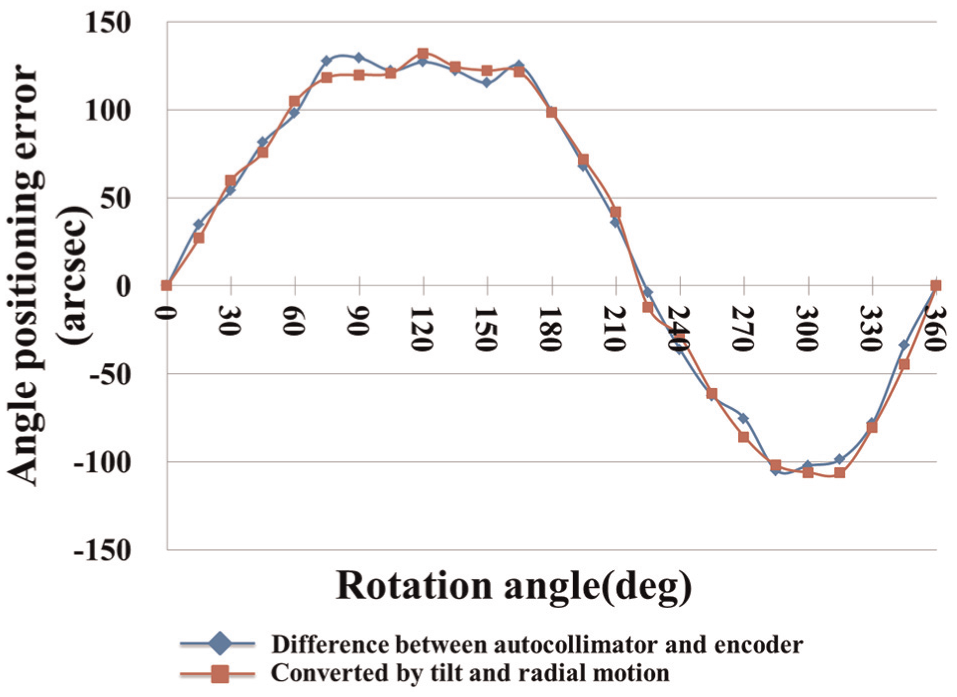
Comparison of angular positioning errors by different error sources.
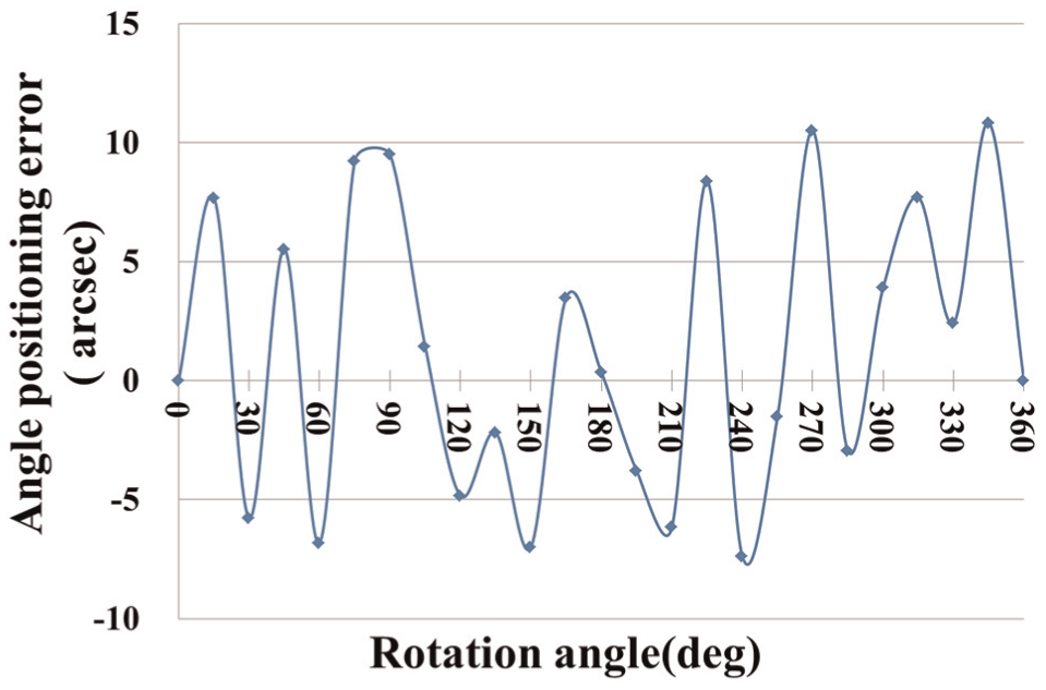
Residual angular positioning errors.
Discussion
From the derivation of equation (2), it is found that the tangential shift of the grating disk with respect to the sensing head is the main cause to the angular positioning error of the rotary stage. Factors that influence the tangential shift could come from the eccentricity of the disk mounting, the tilt and radial errors of the shaft and the accuracy of employed dial gauges. This study addresses the influence of the radial error and the tilt error of the shaft, which are generally the results of imperfect bearings. The studied worm-drive rotary stage has only one bearing that supports the worm gear. Normal direct-drive rotary stage should have two bearings separated at a relatively large distance so as to reduce the tilt motion of the shaft. Some high-precision rotary stages adopt cylindrical-type dense ball bearing to minimize the tilt error. The other two factors are discussed as follows:
Since the radius of the grating disk is normally small, the encoder used in this experiment is 32 mm in radius. Thus, it can be seen from the error equation (equation (2)) that even a 1 µm of displacement measurement error would result in about 6 arcsec of angular positioning error. Therefore, a more accurate displacement sensor should be used in the experiment, such as the interferometer type.
The eccentricity error of mounting the grating disk onto the shaft is an unavoidable term in the rotary stage. To eliminate this error, adopting the encoder with multiple reading heads could be a feasible solution. 29 However, many commercial encoders are equipped with a single reading head. Searching for the encoder with at least dual reading heads could improve prediction accuracy. Precise assembly of the encoder to the rotating shaft is also an important procedure.
Conclusion
In this article, a novel method of analyzing the angular positioning error of rotary stages is proposed based on the concepts of the Abbe principle. Theoretical analysis shows that the angular positioning error of a rotary stage or a spindle is related to the instantaneous tilt and radial motions of the rotating shaft. The length of the bearing system is quite important for reducing the tilt error motion. The distance between the encoder and the bearing system has significant effect on the measurement error caused by the tilt error motion. The encoder with smaller diameter is subject to larger angular positioning error of the stage. The use of multiple reading heads is the most powerful way for eliminating the effects of radial and tilt error motions, as well as the eccentricity error of the grating disk to the shaft, and enhancing the angle measurement accuracy. This study only investigates a rotary stage of the worm-drive type. Experiments of effective error terms were conducted, and the proposed methodology was verified. Other type rotary stages will be studied in the near future.
Footnotes
Declaration of conflicting interests
The author(s) declared no potential conflicts of interest with respect to the research, authorship and/or publication of this article.
Funding
The author(s) received no financial support for the research, authorship and/or publication of this article.