
Abstract
The processing of polymer-bonded explosives is not widely reported in the literature, especially the machining of explosive surrogates in the combined planing and grinding operation known as plano-grinding. The process of machining long pieces of an inert substitute using a wax binder to hold sugar particles together and then subjecting the surrogate material to a linear cutting motion to generate chip fragments is described. The aim and purpose of this work is to analyze the machining of explosive surrogates in terms of chip formation models (oscillating and stress ratio models) and similarity models (chip compression ratio, Poletica, and Peclet numbers). The analysis of machining is compared to standard engineering materials so that the explosives engineer can benchmark machining performance of explosive surrogates to standard materials. The article concludes with statements on how to improve the understanding of machining of explosive surrogates with specifically engineered abrasive cutting tools.
Introduction
The machining of high explosives (HEs) is known to initiate non-shock events that can lead to operator and machine damage. A common family of HE used in practice are termed polymer-bonded explosives (PBXs). The PBX compound modeled in this study is composed of monolithic crystals of β-HMX, a secondary explosive known as cyclotetramethylene-tetranitramine (1.96 crystal density and melting point up to 115 °C), that have linear elastic properties with particle sizes that are designed to initiate explosions at a specified impact energy. When bound in a binder matrix composed of 8 vol.%, the binder acts as a de-sensitizer. Binders are typically 1:1 ratio of elastomer and plasticizer. Experiments conducted by Bowden and Linder 1 showed the effects of coating β-HMX crystals with up to 15% paraffin wax, beeswax, and liquid and solid octadecane. The growth of explosion from the initiation center was seriously affected. The addition of paraffin was found to inhibit the growth of explosion without changing the sensitivity to initiation. The experiments showed that the action of the “de-sensitizer” is to quench the explosion after initiation. This implies that the binder used in the PBX acts as a thermal barrier to prevent the conduction of heat from crystal to crystal, which is most helpful during the machining of these materials where heat is transmitted from the shear zone into the bulk of the material.
A typical microstructure of PBX is shown in Figure 1. 2 The figure shows the PBX 9501 microstructure and can be simulated for machining studies by bonding 8 vol.% paraffin wax to 92 vol.% sugar particles in a 3:1 ratio of granulated sugar to powdered sugar (modal particle size of 290 μm). For a complete understanding of HE, the reader is directed to Bowden and Yoffe’s 3 book on fast reactions in solids. The following sections describe the essential mechanics of chip formation and the use of similarity numbers in the machining of explosive surrogates. The relevance of analyzing chip formation is aimed at reducing the probability of inducing a fast reaction event during the machining of explosives, while the use of similarity numbers in the analysis of machining explosive and their surrogates allows the explosives engineer to characterize the machining characteristics of HEs and their surrogates compared to commonly machined engineering materials.
Chip curvature
Chip curvature is a primary parameter in machining operations from which a continuous chip is produced. The cutting process may be modeled using a primary shear plane and frictional sliding of the chip along the rake face to form a secondary plane.4,5 When the region of chip and tool interaction at the rake face is treated as a secondary shear plane and the shear planes are analyzed by means of slip-line field theory, it is predicted that the chip will form with high curvature. Thus, chip curvature may be interpreted as the consequence of secondary shear along the rake face. Chip curvature is usually associated with the conditions of rake face lubrication. 4 At the beginning of the cut, a transient curvature is often observed, the chip radius increasing as the contact area on the rake face grows to an equilibrium value. The process of continuous chip formation is not uniquely defined by the boundary conditions at a steady state and that the radius of curvature may depend on the build-up of deformation at the beginning of the cut. 5 A treatment of primary chip formation has been derived, which considers chip curvature as a series of heterogeneous elements in continuous chip formation. 6 The free surface of the chip always displays “lamellae,” which are parallel to the cutting edge. The chip is usually considered to form by a regular series of discrete shear events giving a straight chip made up of small parallel segments. It is assumed that multiple shear planes are created owing to the formation of discrete lamellae. However, no account is taken of how the cut material passes over the tool between shearing events. Primary chip formation has been observed by Doyle et al. 7 using transparent cutting tool, and the images shown in their paper provide an understanding of how the chip passes over the surface of the cutting tool.
In studies on the machining of PBX surrogates, the authors noted that chip formation in the initial stages was dominated by shear stresses within the chip until a critical point was reached along the contact face of the cutting edge where bending stresses become significantly larger than the shear stresses that initially created the chip. Astakhov 8 provides a treatment of the effect of bending in chip formation when machining with conventional cutting tools. For cutting with abrasive structures in the plano-grinding operation, modifications are made to Astakhov’s model based on the assumption that the secondary shear zone is composed of much smaller cutting points that are located in such a manner that chips are deformed by bending stresses imposed within the chip by sliding across a rake face that effectively changes the direction of the chip causing the chip to curl according to the curvature imposed by the cutting point that blocks the linear path of the chip as it proceeds along the rake face. The criterion used by Astakhov 8 involved estimating the ratio of shear stress, τ, in the chip caused by compression compared to the bending stress, σb, which is due to the bending moment imposed about the chip. If the ratio of σb/τ > 1, then it is assumed that chip formation is due to bending. If the ratio of σb/τ < 1, then chip formation is due to shear stresses within the chip. By considering the cutting system shown in Figure 2.22 of Astakhov, 8 the plastic shear stress is
where β R is the angle between the normal to the rake face and the direction of the cutting force, R; a1 is the depth of cut; b1 is the width of the cut; φi is the shear plane angle; and γn is the rake angle. For a rectangular cantilever made from an elastoplastic material, the bending moment that fully supports plastic deformation is provided by equation (2)
where My is the yielding bending moment, I is the moment of inertia of the cross section, σy is the yield strength of the material, and c = a1/2 (the half-width of the primary shear plane). According to Astakhov, the bending stress is given by equation (3)
By analysis, the chip–tool contact length based on Astakhov’s model of bending is a function of the chip compression ratio (CCR)

The resultant force is assumed to act halfway along the tool–chip contact length, which leads to the ratio of bending stress to plastic shear stress to be calculated using the following equation
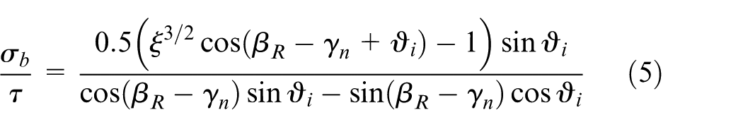
In its most simple form
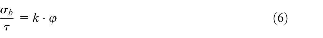
where k is a constant related to the position of the resultant force along the tool–chip contact length (which is 0.5 according to Astakhov 8 ), and
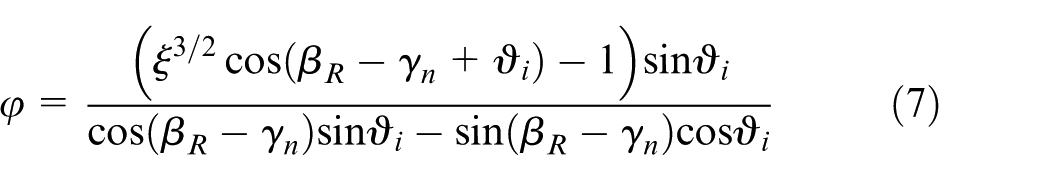
For the studies involving the plano-grinding of PBX materials, tangential and radial components of forces were measured at particular shear angles and compared to chip formation images using a high-speed camera. 9 The advantages of using abrasive structures over plain cutting tool surfaces are many and are associated with the action of individual abrasive cutting points actively changing the tool–chip contact length of the chip over the rake face of the tool. In this study, the tool–chip contact length is based on the calculated CCR for specific plano-grinding conditions and is compared with physical observations. Here, the position of chip curl is observed as the function of calculated tool–chip contact length using photographic images and the resulting ratios of σb/τ are calculated using the data presented in the images.
Similarity models in machining
Similarity theory is of importance in modeling various experimental and industrial situations. Traditional modeling is based on the analysis of physically similar phenomena. Physical similarity may be considered as a generalization of geometrical similarity. Geometrical similarity assumes that two geometric figures are similar if the ratios of all corresponding dimensions are identical. If the similarity ratio scale is known, then simple multiplication of the dimensions of one geometric figure by the scale factor yields the dimensions of the other geometric figure. 8 The numerical characteristics of two different but similar phenomena can be considered as the numerical characteristics of the same phenomenon expressed in two different systems of units. The latter property is significant for metal cutting where variety of the physical systems exist, such as the plano-grinding process. Because the cutting model is commonly developed using one model of chip formation, and the experimental results are obtained using one machine and one process, the use of similarity is the best way to solve the problem. Similarity theory is not yet fully developed for the analysis of metal cutting. However, some useful similarity criteria (numbers) that can be used in modeling of the metal cutting process have been developed.10,11 This section of the article describes the more commonly used similarity numbers in metal cutting, which are compared to similarity numbers applied to the turning of polymer-bonded explosive surrogates (PBX-Ss). 9
CCR
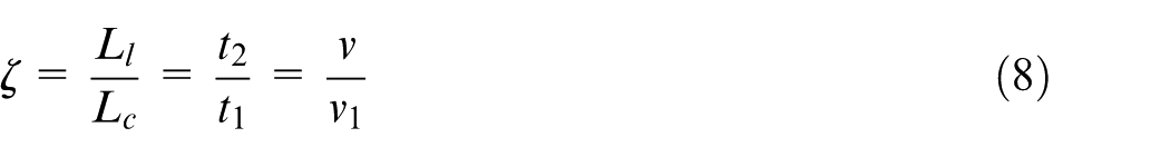
The CCR assures similarity of deformation in metal cutting. Energy spent on plastic deformation of a wide variety of ductile work materials is within the range of 70%–80% of the total energy. 12 CCR can be used to assess the work of plastic deformation in metal cutting, 12 calculate the cutting force, 13 and verify the validity of a finite element model. 14 The CCR (ζ) is determined as the ratio of the length of cut (Ll) to the corresponding length of the chip (Lc) or the ratio of the chip thickness (t2) to the uncut chip thickness (t1), or the ratio of the cutting speed (v) to the chip velocity (v1), that is
CCR is the major determining criterion of similarity in metal cutting. This is because it directly defines the elementary work spent over plastic deformation (Au) of a unit volume of the work material as

where K is the strength coefficient (N/m2) and n is the hardening exponent of the work material. Figure 2 shows the CCR is highest for the machining of copper and lowest for the machining of steel. This fact confused earlier researchers as it is well-known fact that cutting energy and forces are much greater in machining steel. Equation (9) resolves the contradiction. Referring to Figure 2, the elementary work done is the greatest for steel and the least for a PBX-S. In other words, the energy per unit volume spent in the machining of steel is much greater, which results in a larger amount of heat generated and an increase in tool wear.
Therefore, a necessary condition of the similarity of two deformation processes in metal cutting is sharing an equivalent value of Au. This is of significance to the experimental studies in metal cutting because it correlates in a simple way that the work of plastic deformation done in cutting can be correlated to CCR. CCR also allows one to calculate the power spent on the plastic deformation of each layer being removed and on friction at the tool–chip interface. The power spent on the plastic deformation of the layer being removed, Ppd, can be calculated from the CCR and parameters of the deformation curve of the work material as follows8,13
where Aw is uncut chip cross-sectional area (m2)

where dw is the depth of cut (m), f is the cutting feed per revolution (m/rev). CCR represents the true strain in plastic deformation and can be used to calculate the elementary work spent in plastic deformation of a unit volume of the work material. The total work done by the external force applied to the tool can then be calculated. For PBX-Ss, the elementary work done is less than 0.1 GJ at relatively very high cutting speeds (Figure 2). 9
Peclet number (Pe)
Machining requires a moving heat source. Similarity numbers used in thermodynamics to deal with moving heat sources 15 should be utilized for thermodynamic analyses of metal cutting. This is not the case in traditional studies on thermal aspects of metal cutting. To avoid misrepresentation of the experimental data on CCR, this parameter should be determined as a function of the Peclet criterion. Such a representation allows one to account for the combined influence of the cutting regime and thermal properties of the work material. Moreover, one can assess the influence of the thermal energy generated in machining due to plastic deformation and friction on the mechanical properties of the work materials ahead of the cutting edge so that the appropriate work materials model can be used in modeling (analytical, numerical, or physical). The Peclet criterion, often referred to as the Peclet number, is widely used in the thermal analysis of systems subjected to moving heat sources irrespective of temporal dimensions. 15 It is a dimensionless number expressing the ratio of advection to thermal diffusion expressed as
where U is the velocity scale, L is the horizontal length scale, and ww is the thermal diffusivity. In metal cutting, the Peclet criterion is represented in terms of machining process parameters as follows 8
where v is the velocity of a moving heat source (the cutting speed) (m/s) and ww is the thermal diffusivity of the work material (m2/s),
where kw is the thermal conductivity of the work material (J/(m s °C)), and (cp ρ) w is the volume specific heat of work material (J/(m3 °C)). The Peclet number is a similarity number, which characterizes the relative influence of the cutting regime (vt1) with respect to the thermal properties of the workpiece material (ww). If Pe > 10, then the heat source (cutting tool) moves over the workpiece faster than the velocity of thermal wave propagation in the work material so that the thermal energy generated in cutting due to the plastic deformation of the work material and due to friction at the tool–chip interface does not affect the work material ahead of the tool. 11 If Pe < 10, then the thermal energy due to plastic deformation and friction makes a strong contribution to the process of plastic deformation during cutting, and it affects the mechanical properties of the work material when being cut. When deciding which material model to use in the finite element analysis of machining, the following should be observed to select the right model: (a) when Pe < 10, then the machining process is a hot working process and temperature dependent machining models such as the Johnson–Cook, Bammann, Chiesa and Johnson’ model (BCJ), Applied, Japanese, and the Zerrilli and Armstrong models can be used and (b) when Pe > 10, the machining process is a cold working process where machining models can be used that do not have temperature dependence, such as the power law and mechanical threshold models.
Figure 3 shows the influence of the cutting speed on CCR for different feeds. Six complete machining tests were performed. Figure 4 illustrates the result when the Peclet criterion is used as the independent variable. Figure 5 represents another example of experimental data obtained in the machining of H13 tool steel. Such a representation allows the reduction in the number of cutting tests needed to study the amount of plastic deformation in the metal cutting process. It reveals the mutual influence of the cutting regime, tool geometry, and physical properties of the work material on plastic deformation. It is seen that the amount of plastic deformation in cutting for a work material having low thermal conductivity is greater compared to that in cutting a work material having high thermal conductivity. The experimental results show the correlation between the thermal conductivity of the work material and the amount of plastic deformation required to machine it, or simply a measure of “machinability.” The tool rake angle is the only tool geometry parameter that may affect the work of plastic deformation. The influence of the tool rake angle on CCR is shown in Figure 6. CCR does not depend on the tool rake angle if the Pe-criterion is used as an independent variable in machining experiments.
Poletica number (Po)
The tool–chip contact length, also known as the length of the tool–chip interface, determines major tribological conditions at the interface such as temperatures, stresses, and tool wear. Moreover, all the energy required by the system for chip removal is determined by this interface. Therefore, it is of great interest to find a way to calculate its length. To deal with the problem, the Poletica 16 criterion (Po-criterion) is introduced as the ratio of the contact length, lc to the uncut chip thickness, t1
The Po-criterion defines the similarity of the tribological conditions at the tool–chip interface. The major factors that affect the tool–chip contact length are the uncut chip thickness, cutting speed, and rake angle. Only the uncut chip thickness affects the contact length directly. The Pe-criterion strongly depends on CCR and weakly depends on the rake angle as shown from the experimental data presented in Figure 6. For PBX-Ss, the Peclet number is relatively insensitive to changes in the CCR. 9
The influence of rake angle is within the normal experimental scatter. Moreover, it was found that the Po-criterion remains invariant to changes in the mechanical and physical properties of the work material (Figure 7). As shown in Figure 8, the hardness of the work material does not affect the dependence of Po-criterion on CCR. Considering this test, one should note that beryllium copper is an excellent test material because its mechanical properties can be changed in a wide range by heat treatment while the phase composition and microstructural parameters remain practically unchanged.
Figure 9 presents the results of cutting tests with various work and tool materials having a wide range of physical and mechanical properties. The effect of CCR on Po-criterion is clearly shown. Relatively little scatter is reported in terms of rake-angle effects, the greatest variation being in the type of work material used. 9
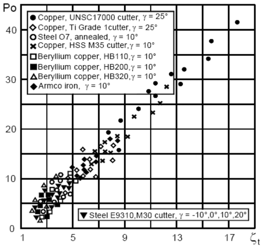
The normalized CCR, ζt is used instead of ζ
where dw1 is the width of the chip. When cutting copper and pure iron, the chip width changes considerably compared to the width of cut (depth of cut). For many other work materials, the ratio dw1/dw ≈ 1. From these initial studies, the turning of PBX-Ss show similarities to the machining of traditional materials, but with much lower amounts of energy required to form chips. With soft materials, it appears that chip formation is not necessarily dominated by the preponderance of stresses in the shear zone, but rather bending stresses imposed on the chip due to frictional interactions along the contact length between chip and cutting tool. The following experimental section shows how chip formation occurs along the cutting tool rake face and how the surface characteristics of that rake face affect the formation of chips and the magnitude of bending stresses in the chip compared to the shear stresses set up in the chip due to frictional interactions between chip and cutting tool.
Experimental procedures
The plano-grinder
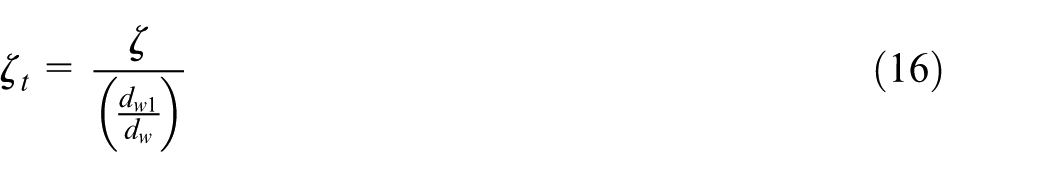
A plano-grinder was developed with the intent to study material interactions with complex tool geometries around the primary deformation zone. Figure 10 shows the machining system components with high-speed camera.
General arrangement of the plano-grinding system showing dynamometer, tool, work material, vise, lighting, and high-speed camera.
The machining system consists of a Newport RS4000 sealed-hole table with tuned damping capabilities. The Newport RS4000 contains a rigid truss honeycomb core thus maximizing dynamic rigidity. The sealed-hole table top ensures alignment of the components of the entire machining system and is rigidly fixed to the damping table using bolts. The tool mounting supports were developed to surround a servo-driven linear slide. An Aerotech ALS 10030 linear positioning stage ALS10030-H-M-80P-BMS-NC-P02 was used in the study. The slide was driven by a precision ball screw brushless servomotor (defined as a BMS60-A-D25-E2000H ATS 10030). The linear slide has the ability to traverse 12 in (304.8 mm) of single axis in a linear manner. The slide is rated to carry a maximum horizontal load of 110 lbf (489 N) and vertical load of 55 lbf (245 N). As the center of gravity of the load on the slide extends from its base, the load capacity decreases proportionally.
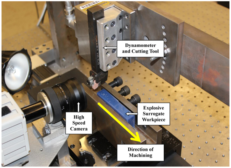
The straightness and flatness of the linear slide system is rated within 0.0002 in (0.005 mm). The servo that supports the linear slide is powered by a 115 V alternating current (AC) transformer module connected to a micro-sized A3200 Ndrive® MP. The linear motion system is precisely controlled using human/machine interface software from a central processing unit connected via wire cable. The Kistler Quartz 3-Component Tool Holder Dynamometer Type 9121, Multi-Channel Charge Amplifier Type 5070, and the Kistler DynoWare Type 2825A-02 software package are used to measure cutting forces. Quartz crystal sensors are considered accurate for measuring force, torque, strain, pressure, acceleration, shock, vibration, and acoustic emissions. The multi component dynamometer measures accurately three orthogonal components of force in the XYZ directions into the top plate of the dynamometer. The robust rigidity of the dynamometer enables small dynamic changes to be measured under large force applications. The Kistler Type 9121 conveniently measures active cutting force and has a high natural frequency suited for metal cutting applications. The natural frequency of the interacting members of the plano-grinder may limit the ability to achieve accurately desirable force measurements. The dynamometer’s three-component force sensors each contain pairs of quartz plates sensitive to its respective direction of force measurement. The force measurement signals are directed through a connecting cable to a charge amplifier and then to the Kistler DynoWare software for study and engineering analysis. The dynamometer needed to be mounted rigidly with the incorporation of altered rake angle orientation capabilities. A mounting plate was designed and machined in order to meet this requirement (Figure 11).
Illustration of tool holder held in the dynamometer and bolted to the mounting plate.
The mounting consists of a steel plate of half-inch thickness. The appropriate bolt hole pattern matching the back side of the type 9121 dynamometer was machined into the plate. A radial bolt hole pattern was drilled and reamed into the mounting plate to supplement the quarter inch (6.25 mm) by 20 threads per inch unified coarse threaded (UNC) bolts and nuts affixing the mounting plate to the large overhanging cross bar. The radial bolt hole pattern was designed minimizing rake-angle alterations to 5° increments taking into account the maximum bolt diameter. The mounting plate has a radial bolt hole pattern that allows experimental observations to occur with the cutting interface of the insert at different rake angles. The mounting plate is held sufficiently to a rigid cross bar that spans the length above the linear slide. A planer-style vise was designed and machined to rigidly hold the work material being studied during the plano-grinding process. The vise for the research planer was designed and machined to hold rigidly the maximum length material with the limited traversable distance of the linear slide used. The planer vise was machined from mild steel. It was considered of highest importance to take into account the intended size of work the vise was to hold. The project researchers settled on building a 1” wide by 1” tall by 8” long work holding capacity (25.4 mm × 25.4 mm × 203 mm). These dimensions do not take into account a quarter-inch (6.25 mm) thick flat clamping plate between five half-inch (12.7 mm) by 13 threads per inch UNC bolts and work material being studied. Researchers using the planer vise have the ability to use precisely ground machinist parallels thus decreasing the amount of material required for machining studies. The planer vise attaches to a flat, hard-coated aluminum plate at its base. The plate is then fixed to the linear slide by four M6 bolts. Between the aluminum base plate and linear slide stage, a precisely ground stainless steel set of shims from control depth of cut within one thousandth of an inch (0.001 in or 0.0254 mm). Intimate mating of all flat surfaces maximizes the plano-grinder’s ability to attain rigidity during the cutting process. Each time the depth of cut is altered by adding or removing shims, the planer vise must be indicated accurately. A magnetic base dial indicator is used and a series of M6 bolts are proportionally tightened (Figure 12). The planer vise attaches rigidly to an alignment plate designed for the linear slides. The open character of the machining system allows for versatility in data acquisition techniques of the cutting zone while producing valuable insight into the tribology of the plano-grinding process.
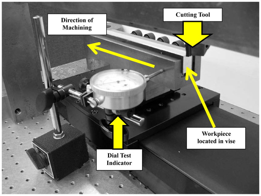
Dial test indicator in use to measure small changes in deviation along the length of the vise.
The open feature of the plano-grinder allows the high-speed camera to analyze the cutting zone as the work material traverses passed the edge of the tool. A Fastcam Ultima 1024 Photron high-speed imaging camera was used in this study. A table-top mounting tripod allows for adjustable heights to permit close examination of material deformation and shear plane characteristics under simulated cutting conditions. The Photron Ultima 1024 high-speed camera system provides researchers the ability to store up to 4000 photographs for analysis. The camera is supported by a Fastcam Ultima 1024 power unit and viewing software PVF 2.4.5.2 was used in this study. The cutting tool used in this work was a section of grinding wheel cut from a standard creep-feed grinding wheel using a band saw that was shaped to fit into the space where an insert tool usually resides. The grinding wheel section was fixed in place using an adhesive joint. The wheel specification was a dual porosity specification white alumina abrasive with vitrified bonding supplied by the Tyrolit company (specification: XA60213VPR).
Preparation of work material
As noted previously, the PBX 9501 microstructure can be simulated for machining studies by bonding 8 vol.% paraffin wax to 92 vol.% sugar particles in a 3:1 ratio of granulated sugar to powdered sugar (granulated sugar particle sizes range from 400 to 600 μm, whereas powdered sugar consists of 17% maximum of particles sizes above 212 μm and 23%–55% of particles are below 53 μm). Grains of sugar look similar to crystals of β-HMX (Figure 13) and are bonded with paraffin wax using the methods previously explained.
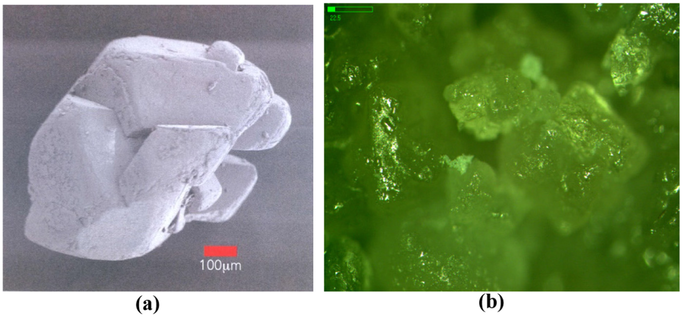
(a) Crystal of β-HMX2 and (b) granulated sugar crystals.
Initially, cylinders of explosive surrogates were made specifically for the purposes of studying machining by turning. The samples were 6 in in diameter (6 in or 152.4 mm) and were molded using a short plastic pipe in which to cast the material. The wax was first melted then mixed with the sugar crystals on a hot metal plate then prepared for casting. For plano-grinder samples, the mixtures were placed in a mold for producing rectangular shapes. Samples of sugar mixed with molten wax produced samples with an inconsistent gradient, so solid wax was shredded and mixed with the sugar crystals then heated to allow the wax to melt and bond to the sugar crystals prior to casting in the mold. The mixture was molded in a mold producing machining blocks that were 95 mm in length, 13 mm in width, and 30 mm in depth. The cooled block was bolted into the vise and machined to produce a surface that was true to the grinding tool insert. The depth of cut was initially set to 0.02 in (0.508 mm) and the linear cutting speed set to 6.333 mm/s. The speed selected allowed a 95-mm-length block to be machined in 15 s. The initial results were conducted with paraffin wax and sugar to establish baseline studies to compare other explosive surrogates such a talc/binder mocks and barium nitrate/binder mocks, which will the form the basis of future experimental studies on the machining of PBX surrogates.
Experimental results and discussion
Chip formation
Initial high-speed photographic studies of chip formation with wax binders and sugar particles are shown in Figure 14. When observing the images of chip formation, Figure 14(a) shows a negative rake abrasive-bond structure with a slight edge radius of slightly under 0.05 in (1.25 mm) ahead of the work material. The cutting tool has made contact with the surface of the surrogate and chip formation begins after 1.68 s as shown in Figure 14(b). When 2.52 s of time has elapsed, the chip begins to oscillate about the primary shear plane and a rather pronounced negative angle is produced as shown in Figure 14(d). A second chip is produced after the initial chip has formed. This is shown in Figure 14(e) and its formation started after a 4.5 s time interval. Here, the chip is much thicker than the first, but still has the oscillatory motion associated with it, but now associated with significant bulging of the chip. The bulging chip is growing thicker in the subsequent frame (Figure 14(f)) after 5.04 s of time have elapsed since the initial chip was formed. The frame also shows that the secondary chip is moving toward the camera, showing the bulged manner of its formation quite clearly. Figure 14(g) shows a third chip being formed after 7.56 s, while the secondary chip is moving in a downward fashion toward the surface of the work material. This type of chip is serrated and is moving toward the camera as shown in Figure 14(h).
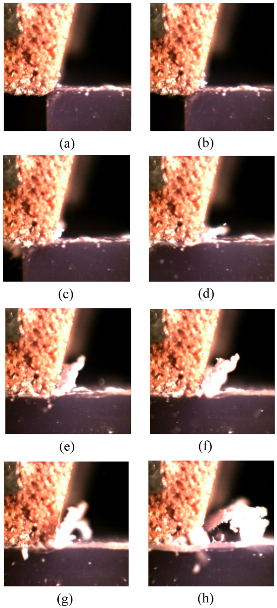
Initial chip curvature formed at intervals of cut: (a) T = 0 s, (b) T = 1.68 s, (c) T = 2.52 s, (d) T = 3.36 s, (e) T = 5.04 s, (f) T = 5.88 s, (g) T = 7.56 s, and (h) T = 9.24 s.
The fact that three chips have formed indicates that multiple secondary shear planes exist on the rake face of the tool, which is understandable as multiple cutting points are located on the same rake face, albeit very small abrasive cutting points. The sequence of chip formation shown in Figure 14 is described schematically in Figure 15. The chips are indentified as “continuous fragmentary humpbacked” chips where zones of sliding and deposit formation are observed (Astakhov’s 8 Model C). The chips show zones of sliding that is periodic in nature, but is fragmented by a deposit stage that has “bulged” during its adherence to the cutting edge. The instability shown by the chips is common in ductile materials and is due mainly to periodic seizure at the chip–tool interface. This is commonly exhibited when machining aerospace materials such as chromium and/or high nickel content alloys or soft materials such as paraffin wax. 8 The chips formed when machining ductile materials are shown by Astakhov 8 as having difficult to distinguish elements and a variable thickness along their lengths. Clearly, chip formation model C is applicable to chip formation when machining explosive surrogates containing paraffin wax. 8 The advantages of having an abrasive insert is that it provides multiple cutting points on the rake face so that multiple chips can be formed that are smaller and more manageable to remove. It is clear from the schematics (Figures 15 and 16) that there is a transition from primary to secondary chip formation resulting from the change in CCR and the position of chip as it slides along the rake face of the tool, impacting the abrasive grain obstacle then forming the chip clear of the surface of the rake face. Figure 16 shows how the abrasive grains change the way in which chips are formed by imposing variable curvatures on the chips formed that result in chips tending to form an angle β, β′, β′′, and so forth depending upon where the chip touches the abrasive grain on the contact face of the cutting tool and the position of the pivot point of the resultant force. In terms of Astakhov’s analysis, a perfectly formed chip on a smooth surface pivots when k = 0.5. For the abrasive structured cutting tool surface used in this study, the value of k is a function of the spacing between abrasive grains and the CCR. For the abrasive structure used in this study, the value of k varied between 0.2 and 0.6. When calculating the stress ratio within the chip, the stress ratio is dependent on the position of the resultant force along the tool–chip rake face, and for the experimental conditions described in this article, the ratio varied between σb/τ = 0.2φ and σb/τ = 0.6φ.
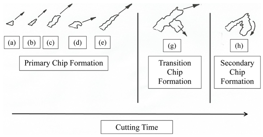
Schematic representation of chip formation for the plano-grinding of PBX surrogates.
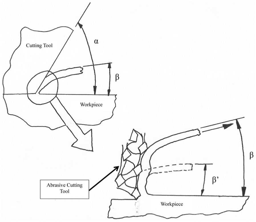
Schematic representation of chip formation for the plano-grinding of PBX surrogates showing rake angle, α, in relation to chip formation angles, β and β′.
A model of chip curvature was developed and agrees well with observed images of positive angle chip formation. 6 It appears that the oscillating negative angle of rake contributes significantly to the shape and direction of the primary chip prior to significant frictional interactions on the rake face of the cutting tool. It is shown that primary chip curvature is initiated by the amount of material deposited onto the cutting tool that manifests itself as a wedge angle that controls the amount of material pushed into the base of the segment of the chip between oscillations of the primary shear plane. The experimental results suggest that a number of primary shear planes are created during the initial stages of chip formation that contradicts the assumptions made by other researchers. 5 Although their experiments were characterized by machining soft, ductile metals at low speeds, it seems appropriate to suggest that their model cannot be initially applied to the machining of ductile materials. However, a series of single shear planes dominated by dynamic shearing events may describe the machining of a highly ductile material as described by Astakhov. 8 By measuring the spacing of lamellar on formed chips, the shear strain rate was measured to be in the range 2000–4000 s−1, while the measured chip curvature varied between 4 and 6 mm.
Edge breakdown of the grinding tool was noted for abrasive structures that possessed edge radii that were smaller than 10 times the abrasive grain size. Therefore, the effective grain diameter to be chosen for the corresponding tool edge radius should be, dgrain = r/10. In this case, the radius of the tool edge is 1.25 mm (1250 μm). Therefore, the minimum grain diameter that should be chosen for this particular edge radius is 125 μm (or 100 abrasive number in terms of the Norton classification system).
Similarity models
The CCR was calculated for the machining described earlier and focused on calculating the CCR for three chips that were generated during the initial stages of machining the explosive surrogate blocks, that is, primary, transition, and secondary chip formations. The uncut chip thickness, t1, was 0.02 in (0.508 mm), and the thickness of each chip generated was 0.02, 0.0266, and 0.0333 in (0.5, 0.675, and 0.846 mm), respectively. The calculated CCR was 1, 1.333, and 1.667, respectively. The low CCR shows that the amount of work done in creating a chip in explosive surrogates is very low indeed and should be less than that for soft aluminum (less than 0.1 GJ, according to Figure 2). The true strain represented here produces very low frictional work at the chip–tool interface. This is helpful in that there will be a very low tendency to initiate and grow a localized hot spot at the center of chip compression ahead of the tool edge and beyond.
The calculation of the Peclet number for the system under consideration required to understand the thermal diffusivity of paraffin wax. Paraffin wax is a hydrocarbon compound belonging to the alkane group and has the general formula CnH2n + 2. A typical component of paraffin wax is C31H64. Paraffin wax has a melting point in the range 46 °C–68 °C, a specific heat capacity of 2.14–2.9 J/(g K), heat of fusion between 200 and 220 J/g, and density of approximately 900 kg/m3. It produces hexagonal and/or needle-shaped crystals and is reported to possess a thermal diffusivity of 0.97–1.02 × 10⁻⁷ m2/s. 17 To calculate Pe number, the cutting velocity was calculated to be 6.33 × 10⁻³ m/s, the uncut chip thickness was 0.508 mm, and the most conservative value of thermal diffusivity being 0.97 × 10⁻⁷ m2/s. Therefore, Pe was calculated to be 33.15. It is seen that for the machining of the explosive surrogate, Pe > 10. This means that the machining process is a cold working process where machining models can be used that do not have temperature dependence, such as the power law and mechanical threshold models. Pe number for the explosive surrogate corresponds to a low CCR between unity and 1.667. For these levels of CCR, one would expect Pe to be much greater than 560 if the material was metallic judging by the data provided in Figure 6. However, the explosive surrogate has a high thermal conductivity that requires much less plastic deformation to produce a chip; therefore, Pe number is expected to be low for such small CCRs. The fact that explosives can detonate at significant levels of plastic deformation means that the small values of CCR encountered during machining will less likely cause the explosive to detonate during machining. As an added safety measure, a de-sensitizer is added to the explosive material to ensure that detonation occurs at higher levels of plastic deformation than those normally encountered during the machining process.
According to Poletica, the contact length is calculated using the following equation, LC = h(2.05ξ−0.55), Where LC is the contact length, h is the undeformed chip thickness, and ξ is the chip thickness ratio. From the chip thickness calculations shown above, the chip thickness ratio ξ = t2/t1. For the experimental conditions shown, ξ was calculated to be 1, 1.333, and 1.667, respectively. From these calculations, the contact length was calculated to be 0.762, 1.108, and 1.454 mm, respectively. The calculated Po numbers range from 1.5 to 2.862, for the machining operation described. The Poletica number defines the similarity at the chip–tool interface and the values generated for the explosive surrogate show that the contact length is very small compared to the uncut chip thickness. This is influenced heavily by the rake angle of the cutting tool. As the rake angle increases, the Po number increases. In this case, it is clear that when machining explosives and their surrogates, rake angles should be as large as possible (>20°) so that the CCR is relatively small. The rake-angle effect will dictate whether, or not, frictional contact along the rake face between chip and tool can be minimized in order to avoid detonation of the explosive. In the case of machining explosives and their surrogates, Po and CCR should be less than unity.
Conclusion
The conclusions of this work mainly focus on chip formation in plano-grinding an explosive surrogate. The work carried out by Doyle et al. 7 and developed further by Jackson 6 has shown that positive chip curvature can be created with an oscillating negative rake angle cutting tool. The use of abrasive particles on the rake also produces multiple chips that are much smaller than chips produced using a traditional single-point machining insert. The chip form was predominantly fragmentary with “bulging” cross sections caused instabilities that occur during chip formation primarily due to periodic seizure at the chip–tool interface. This type of chip formation corresponds to Model C as described by Astakhov. 8 The spacing of abrasive grains on the rake face of the cutting tool has a direct influence on the position of the applied load and the angle at which the chip forms in relation to the ratio of stresses, σb/τ. Further work needs to be conducted to correctly identify how the spacing of abrasive grains affects chip formation in terms of shear and bending stresses imposed on the chip during the plano-grinding operation.
For the plano-grinding operation described, CCR was calculated to be 1, 1.333, and 1.667, for the chips generated during machining. Consequently, the Peclet number (Pe) was calculated to be 33.15. As Pe > 10 for this machining operation, it can be considered a “cold working” process. The Poletica number (Po) was calculated to be 1.5, 2.181, and 2.862, for the plano-grinding operations, respectively.
From this study, it is concluded that CCR and Po should be less than unity in order to minimize the inducement of premature detonation caused by frictional interactions along the rake face of the cutting tool. Also, low values of CCR indicate that insignificant plastic deformation occurs when chip formation takes place. This means that premature detonation of the explosive is less likely to occur prior to the chip rubbing against the rake face of the cutting tool. In order to minimize the occurrence of pre-detonation, cutting tools should remain sharp and should be presented to the explosive surrogate at an angle of 20° or more.
Further studies using talc/wax and barium nitrate/wax mocks are planned in addition to using the traditional sugar/wax compositions of variable sugar/wax ratio.
Footnotes
Acknowledgements
The authors acknowledge the assistance of Eric Huber for developing the procedures associated with pressing and processing the wax/sugar mocks. Thanks are due to Prof. Astakhov for supplying the original images and for the discussions on cutting of soft materials. The authors thank Los Alamos National Laboratory (especially to Clay Dillingham, Managing Editor of the National Security Science Magazine) and Elsevier (License Number: 3791130627788, granted 16 January 2016) for permissions to use data and images and to annotate the images/figures for use in this article that were derived from Prof. Astakhov’s work published in Elsevier’s “Tribology and Interface Engineering Series.”
Declaration of conflicting interests
The author(s) declared no potential conflicts of interest with respect to the research, authorship, and/or publication of this article.
Funding
The author(s) received no financial support for the research, authorship, and/or publication of this article.