
Abstract
Ultra-high-strength steel sheets having a tensile strength of more than 1 GPa and a low ductility were joined by mechanical clinching with dies for control of metal flow. The bottom angle of the die was modified to increase interlocking between the sheets under avoidance of the sheet fracture. The effect of the die shape on metal flow in the sheet combination including an ultra-high-strength steel sheet was investigated by the finite element simulation and the experiment. As the tensile strength of the steel sheets increased, the joining range was narrow due to low ductility of the sheets. The static and fatigue strengths of the mechanically clinched joints were compared with those of the welded joints. Although the static loads of the mechanically clinched joints were smaller than those of the resistance spot welded joints in both tension-shearing and cross-tension tests, the fatigue loads of the clinched joints were larger. It was found that the mechanically clinched joint has superior fatigue strength.
Keywords
Introduction
To reduce the weight of automobiles, the use of high-strength steel and aluminium alloy sheets tends to increase because of their high specific strength. The mild steel automobile parts tend to be replaced with high-strength steel ones for the reduction. Particularly, ultra-high-strength steel sheets having a tensile strength of more than 1 GPa are attractive for the reduction. The high-strength and ultra-high-strength steel parts are conventionally joined by resistance spot welding. The static load of the joint by resistance spot welding becomes larger as the tensile stress of steel sheets increases, whereas the increase in the fatigue strength of the joint is not large. 1 The initiation and propagation of cracks in the high-strength steel and ultra-high-strength steel sheets are sensitive. 2 The development of a joining process for attaining high fatigue strength of joints for the high-strength steel sheets is desirable in the automobile industry.
Mechanical clinching is a cold joining process of sheets by local hemming with a pair of punch and die in general and is used for joining of automobile parts.3,4 The mechanical clinching of ultra-high-strength steel sheets is not easy. The fracture tends to occur during joining of ultra-high-strength steel sheets due to low ductility although Varis5,6 had joined the high-strength steel sheets. Neugebauer et al. 7 had developed a mechanical clinching process by heating dies for the magnesium alloy sheets. But the heating time of the steel sheets becomes long. Using dies for control of the metal flow is effective in the joining of the ultra-high-strength steel and aluminium alloy sheets. 8 The ultra-high-strength steel sheets are joined by the mechanical clinching having control of the metal flow with an optimum die shape and using the cemented carbide punch. 9 The clinching of the ultra-high-strength steel sheets having lower ductility is more difficult. Although the 1-GPa steel sheets having lower ductility were joined by the counter pressure of an elastomer, 10 the joining cost was not low.
The finite element simulation is useful to design the clinching process. 11 The effect of the shape parameters of the tools on the interlock and separation load of the joint was investigated by De Paula et al. 12 Carboni et al. 13 found that the location of crack formation in the fatigue test of steel sheets joined by the mechanical clinching corresponds to that at concentration of stress calculated from finite element simulation.
In this study, the ultra-high-strength steel sheets having a low ductility were joined by mechanical clinching with the dies for control of metal flow. The bottom shape of the die was modified to increase interlocking between the sheets under the avoidance of the occurrence of sheet fracture. The effect of die bottom angle on metal flow in the sheet combination including 1.2 GPa of the tensile strength steel sheet was investigated by a finite element simulation and an experiment. In addition, the static and fatigue joint strengths of mechanically clinched sheets were compared with those of resistance spot welded sheets.
Mechanical clinching with die bottom angle and conditions
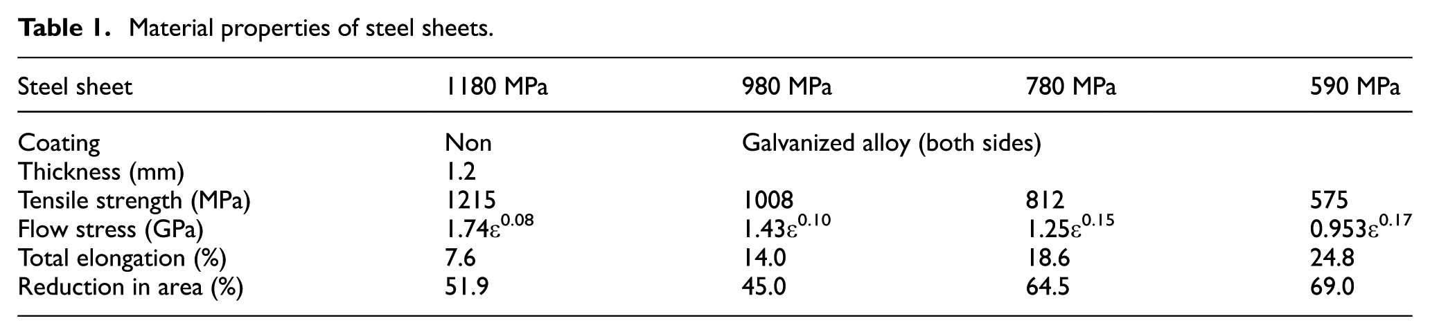
The material properties of the steel sheets used for mechanical clinching are given in Table 1. The 590- to 980-MPa steel sheets are galvanized alloy-coated ones having high corrosion resistance. As the tensile strength of the sheet increases, n-value and total elongation decrease. The 980- and 1180-MPa steel sheets have small reduction in area.
Material properties of steel sheets.
In the conventional mechanical clinching, the sheets are formed by the punch and die to generate the interlock Δx between the lower and the upper sheets as shown in Figure 1(a). The upper and lower sheets are joined by being hooked on the interlock generated around the punch corners, whereas the thickness of the upper sheets decreases around this corner. The upper sheet on the punch corner is bulged during the early stage in clinching. The reduction is accelerated by the compression from the lower sheet, and then fracture appears if the excessive reduction occurs. The critical wall thickness of the upper sheet around the punch corner without fracture is required. An appropriate joint strength of the sheets is obtained from the interlock and minimum wall thickness tmin. Although the small metal flow of the sheets brings the prevention of the fracture of sheets, the interlock becomes small. The interlock is increased by the angle of the die bottom because the metal flow of the lower sheet becomes larger than that of the upper sheet in Figure 1(b). The tool geometries used for mechanical clinching are illustrated in Figure 1(c). The effects of depth h and angle θ of the die on the metal flow of the sheets were investigated by a finite element simulation and an experiment. The final punch load was fixed to 70 kN to avoid plastic deformation of the punch. The upper sheet has 1.2 GPa of tensile strength steel. The tensile strength steel of the lower sheet is from 590 MPa to 1.2 GPa.
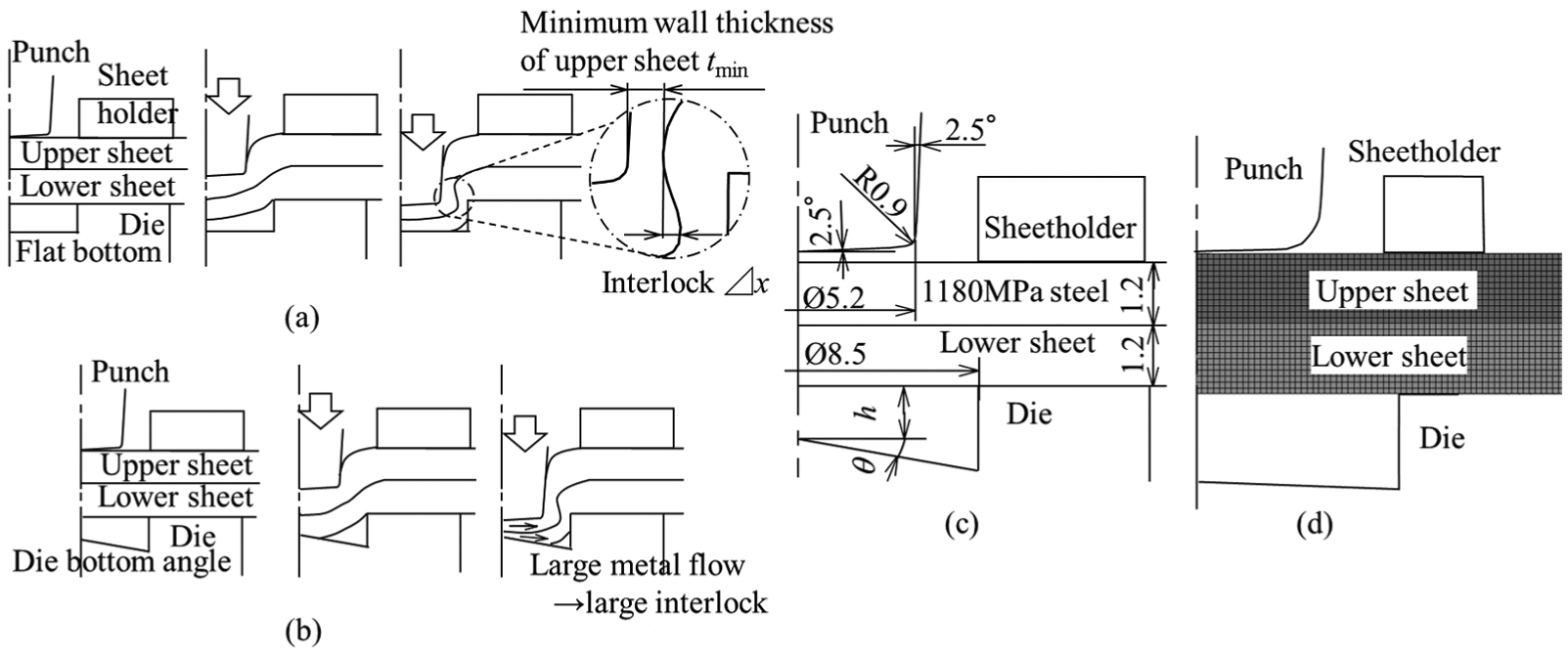
Mechanical clinching with die bottom angle and conditions: (a) mechanical clinching without die bottom angle, (b) mechanical clinching with die bottom angle, (c) mechanical clinching conditions and (d) conditions of finite element simulation.
In the finite element simulation, the commercial finite element code LS-DYNA was used. Since axi-symmetric deformation was assumed by limiting the calculation to the vicinity undergoing plastic deformation, the cross sections of the sheets were divided into quadrilateral elements. The flow stresses of the sheets are shown in Table 1. The sheets underwent plastic deformation during the joining process, and the die, punch and sheetholder are assumed to be rigid. The coating layers do not require treatment. The law of Coulomb friction was used as a friction model in the simulation, and the coefficient of friction at the interface between the tools and sheet was 0.08. The calculation time was about 70 min by Intel Xeon CPU E3-1275 V2 processor.
Improvement of metal flow
The deformation behaviour of the sheets in the mechanical clinching obtained from the calculation and the experiment is shown in Figure 2. The interlock was formed in the mechanical clinching with die bottom angle, whereas the interlock was not formed without die bottom angle. The bottom wall thickness of the sheets was reduced by the bottom angle of the die as shown in Figure 2(c), and then the metal flow to the die corner was increased. The deformed shape of the sheets obtained from the calculation was similar to that of the sheets joined in the experiment.
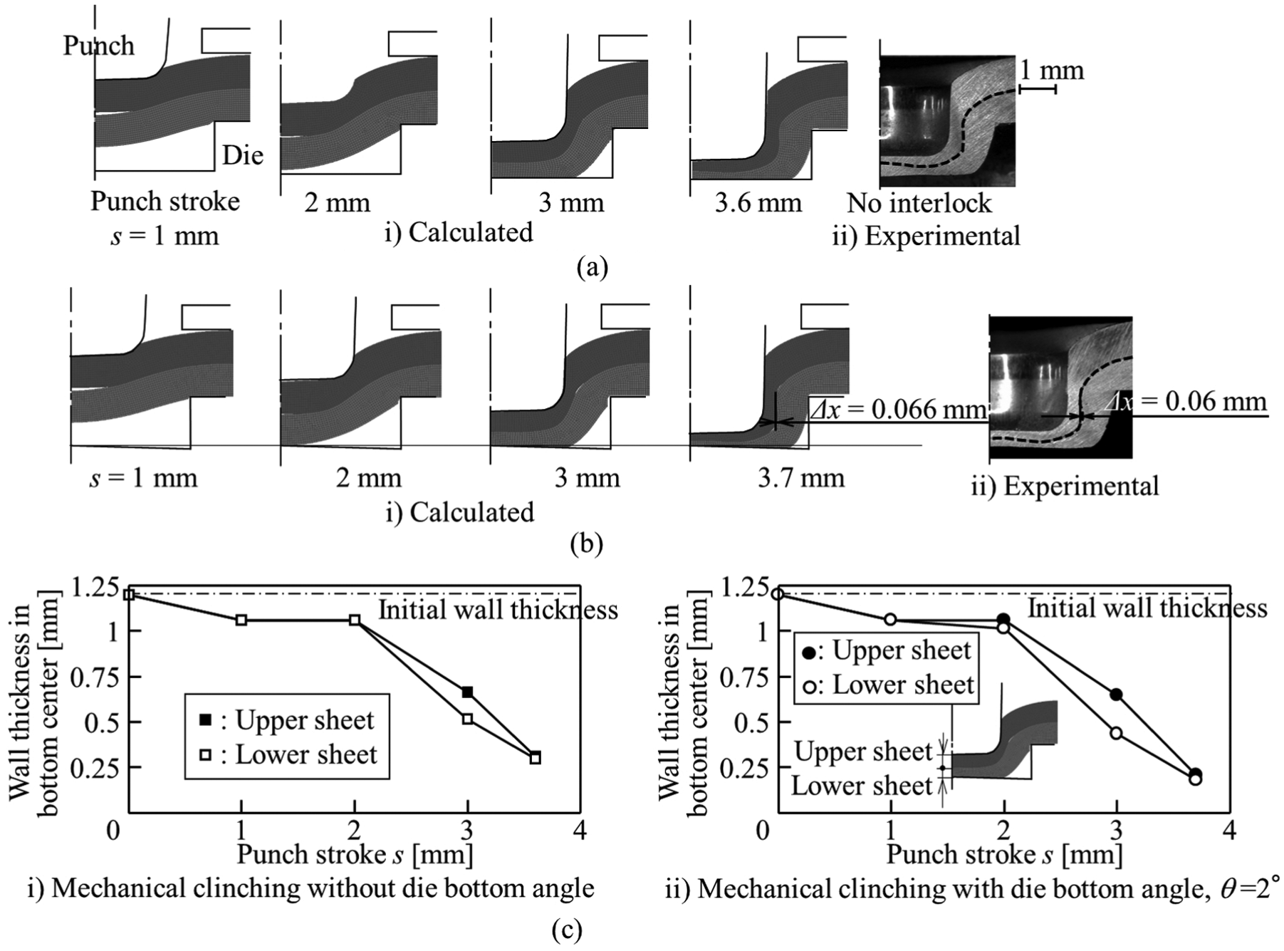
Deformation behaviour of sheets in mechanical clinching obtained from calculation and experiment for combination of upper 1180-MPa and lower 780-MPa steel sheets and h = 1.8 mm: (a) mechanical clinching without die bottom angle, (b) mechanical clinching with die bottom angle, θ = 2° and (c) calculated wall thickness in bottom centre.
The effect of die shape on the joining range obtained from the experiment is shown in Figure 3. As the tensile strength of the steel sheet increases, the joining range becomes narrow. In the upper sheet fracture, the upper sheet fractures because the reduction in wall thickness of the upper sheet becomes large. In the no interlock, the interlock does not generate because of the small metal flow of the sheets. In the cracks, the cracks occur on the bottom corner of the lower sheet because of the large plastic deformation and low ductility of the sheet. In both the small die depth and small die bottom angle, the no interlock tends to occur. In contrast, the upper sheet fracture and cracks tend to occur in both the large die depth and large die bottom angle. In the moderate shape of the die, the 590- and 1180-MPa steel sheets and the 780- and 1180-MPa steel sheets are joined without defects. The 980- and 1180-MPa steel sheets are joined with cracks on the bottom corner of the lower sheet because of low ductility of the sheet. 1180 MPa steel sheets and joined with cracks for h = 1.2 mm and θ = 10° because of large flow stress and low ductility of the sheet. Cracks are not suitable for high fatigue strength of joints. The material between punch and die bottoms flows to die corner much by the die bottom angle in the clinching. The material flow brings large interlock, and then the joining range becomes wide. However, the material flow does not only bring large interlock but also the reduction in the wall thickness on the punch corner because of large metal flow to the die corner.
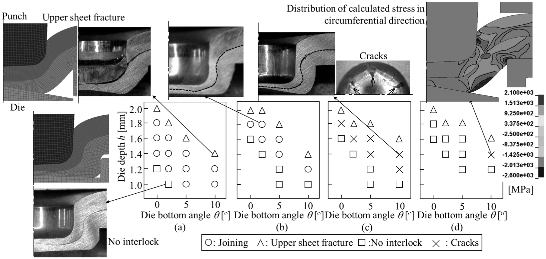
Effect of die shape on joining range obtained from experiment combination of upper 1180-MPa and lower (a) 590-MPa, (b) 780-MPa, (c) 980-MPa and (d) 1180-MPa steel sheets.
The effect of the die shape on the interlock and the minimum wall thickness of the upper sheet is shown in Figure 4. The minimum wall thickness of the upper sheet and the interlock are measured from the cross-sectional shape of the joined sheets and are the average of both the sides. The conditions in the largest die depth are selected because the interlock tends to be large. 8 The minimum wall thickness is more than 0.42 mm because the upper sheet fracture is prevented. The interlock in the 780 MPa becomes smaller due to the large flow stress of the sheets. For 780-MPa steel sheet, h = 1.8 mm, θ = 0° and 2° in Figure 4(b), the minimum wall thickness is reduced due to the bottom angle whereas the interlock was increased.
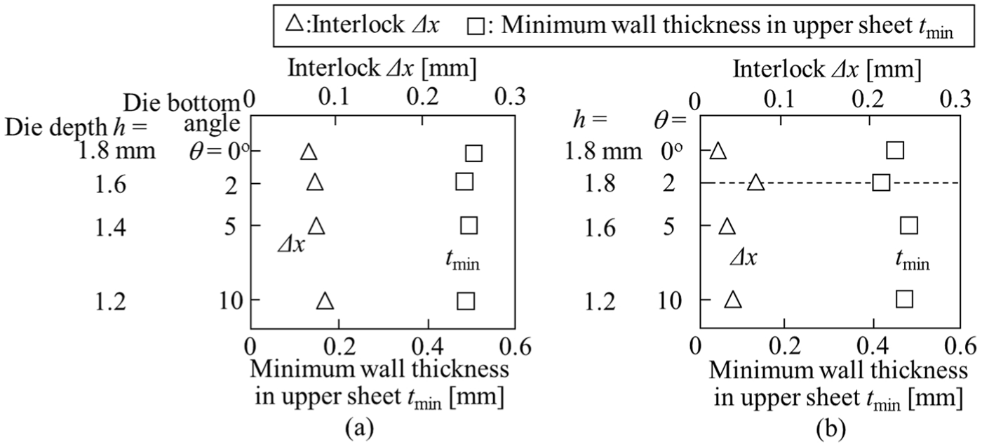
Effect of die shape on interlock and minimum wall thickness of upper sheet: (a) 590 MPa and (b) 780 MPa.
Joint strength
The strength of the joined sheets by the mechanical clinching was measured by the tension-shearing (JIS Z3136) and cross-tension (JIS Z3137) tests. The measuring condition was chosen on the basis of the Japanese Industrial Standard Committee. The strength was compared with that of the welded sheets by resistance spot welding for a sheet combination of upper 1180-MPa and lower 780-MPa sheets. The die depth and the die bottom angle are 1.8 mm and 2°, respectively. The welding conditions and the cross-sectional shape of the welded sheets are shown in Figure 5.
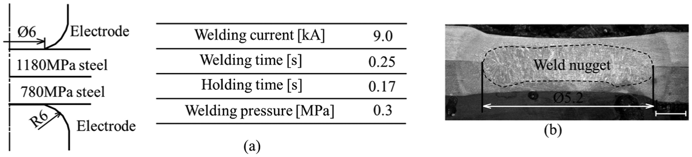
(a) Welding conditions and (b) cross-sectional shape of welded sheets.
The static joint strength for tension-shearing and cross-tension tests is shown in Figure 6. The maximum loads of the clinched joints in tension-shearing and cross-tension tests are smaller than those of welded joints. The fracture occurs around the weld nugget in both tension-shearing and cross-tension tests because of the annealed portion by heating. In the tension-shearing test for the clinched joint, the fracture occurs in the minimum wall thickness portion of the upper sheet, thus the minimum wall thickness is required to increase the load. On the other hand, the upper sheet was pulled from the lower sheet in the cross-tension test, and thus the interlock is required to increase the load.
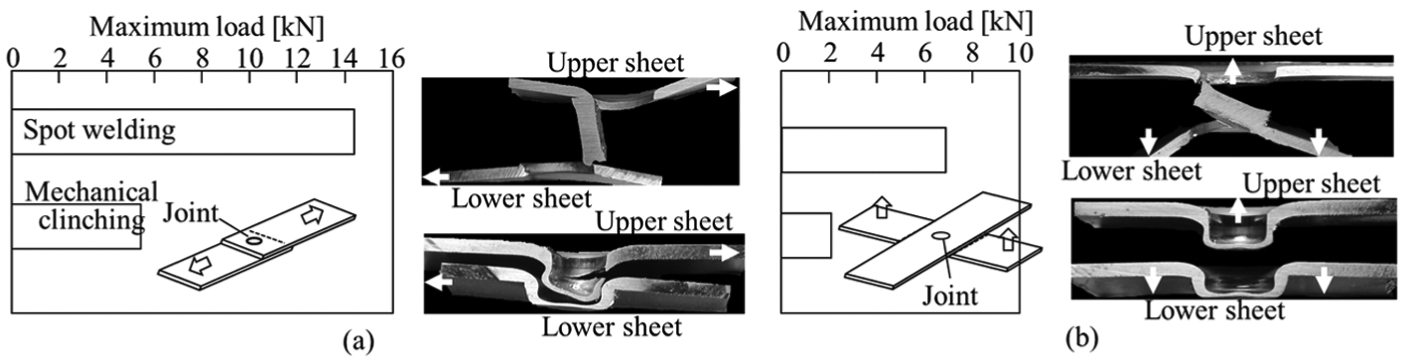
Static joint strengths for combination of upper 1180-MPa and lower 780-MPa sheets: (a) tension-shearing test and (b) cross-tension test.
The fatigue joint strength for tension-shearing and cross-tension tests is shown in Figure 7. The fatigue test was ended when the displacement became excessive. The repeated load cycle between tension and unloading was employed under a frequency between 5 and 30 Hz. As the number of cycles increases, the load amplitude decreases. The load amplitude of mechanical clinching at 107 of the number of cycles was larger than that of resistance spot welding. The stress concentrates at the edge of the weld nugget due to the complete bonding in the resistance spot welding, whereas the concentration of stress is relaxed by the slight slip at the interface between the sheets for the mechanical clinching. 14 It was found that the mechanically clinched joint has superior fatigue loads.
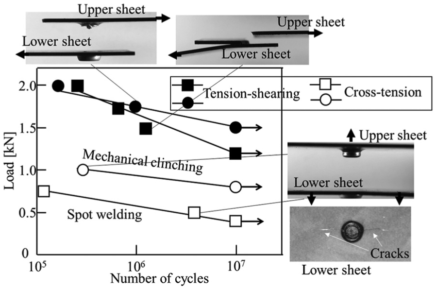
Fatigue joint strengths for combination of upper 1180-MPa and lower 780-MPa steel sheets.
Conclusion
The mechanical clinching with the die bottom angle was developed to join the sheet combination including the 1.2-GPa steel sheet. The interlock was increased by the metal flow of the sheets with the angle of the die bottom. In the sheet combination including more than the 1-GPa steel in the lower sheet, cracks were shown in the bottom corner of the lower sheet. Although the maximum static load of the clinched sheets was smaller than that of the welded sheets, the fatigue load of the clinched sheets in the high number of cycles was larger than that of the welded sheets.
Footnotes
Appendix 1
Declaration of conflicting interests
The author(s) declared no potential conflicts of interest with respect to the research, authorship and/or publication of this article.
Funding
The author(s) received no financial support for the research, authorship and/or publication of this article.