
Abstract
Strain monitoring is very important in the manufacturing, assembling, installation and servicing processes in both mechanical and civil engineering fields. Two-dimensional digital image correlation is a simple, efficient strain monitoring method, but one major bottleneck is the unacceptable error due to the unavoidable out-of-plane motions of the object in practice. We propose a “self-correction” method: employing the originally extracted strain values in different directions to correct the errors due to out-of-plane motions. It is applicable to many engineering applications with known relationship of strains in different directions. A uniaxial tension test was conducted to demonstrate the effectiveness and practicality of this self-correction method. Compared with other correction methods, this method is not only simpler but also more efficient in correcting errors due to the lens distortion caused by self-heating. Both the experiment and theoretical analyses demonstrate that this self-correction method maintains the high accuracy of the digital image correlation method.
Introduction
Strain monitoring is very important in the manufacturing, assembling, installation and servicing processes in both mechanical and civil engineering fields.1–3 Strain gauge is an accurate, local strain monitoring method, but does not work well in harsh environment, because the gauge itself and its attachment to the object can be easily damaged by mechanical forces or other factors. Digital image correlation (DIC) is a promising, non-contact, full-field strain monitoring technology. The basic principle of DIC is to take digital images of the object surface in both “reference” and deformed states and then compare the images to calculate the strains.
Since it was first proposed in 1980s,
4
DIC has undergone remarkable modifications and improvements. The correlation algorithm has been well developed and then implemented into commercial and open-source codes, achieving a measurement accuracy of 0.01 pixel for displacement and 100
Previous studies have proposed a few correction or minimization methods. Pan et al. 9 employed a high-quality bilateral telecentric lens to increase the “effective” object distance, so that the sensitivity to out-of-plane motions would be reduced. The drawbacks of this approach are the fixed field of view, limited depth of focus and high cost of a bilateral telecentric lens. Hoult et al. 10 used two cameras on the two sides of the test steel plate to distinguish between actual strain and the “virtual” strain caused by out-of-plane motions. This approach is not generally applicable, for example, complex structures which do not have two sides as steel plates. Pan et al. 11 attached a rigid reference sample to the test object, so that the out-of-plane displacement can be evaluated and then the resultant error can be corrected. But in some engineering applications, it is not easy to ensure the attached reference sample undeformed. For example, the thermal expansion of the reference sample is unavoidable, or strain will be introduced by the centrifugal force when the reference sample is attached to a rotating object.
In this study, we propose a “self-correction” method. In many engineering applications, the load is only applied in one direction, for example, a uniaxial tension test or the relationship between strains in different directions are known, for example, a cylinder under an internal pressure. For these cases, we propose to use the known relationship of strains in different directions to correct the errors caused by out-of-plane motion, with no extra setup needed. This approach is even simpler than the aforementioned methods and also maintains the high accuracy. The “self-correction” method is presented based on the theoretical analysis of the error due to out-of-plane motions in section “Theoretical derivation of the ‘self-correction’ method.” This method is verified and compared with the rigid reference method 11 by performing a uniaxial tension experiment in section “Experimental verification.” Both the experimental comparison in section “Experimental verification” and the theoretical analysis in section “Discussion” confirm that the “self-correction” method maintains the high accuracy.
Theoretical derivation of the “self-correction” method
Theoretical analysis of the error due to out-of-plane motion
Out-of-plane motions include out-of-plane translation, out-of-plane rotation, and their combination. Figure 1 schematically shows the effects of out-of-plane translation and out-of-plane rotation on the in-plane dimensions of the image. Let
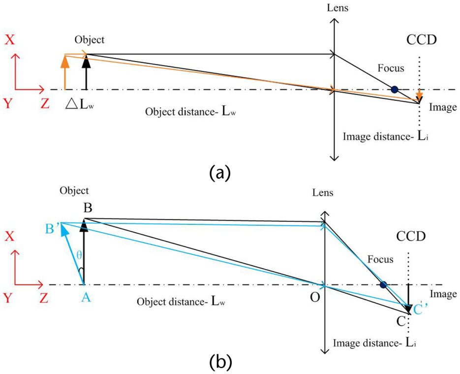
Effects of out-of-plane motion on image in-plane dimensions: (a) translation and (b) rotation.
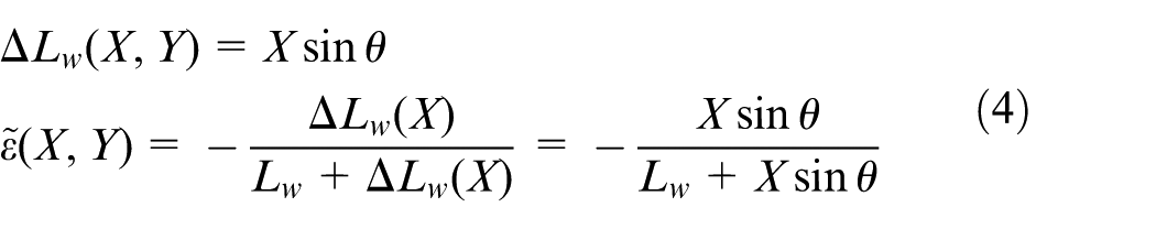
When a small out-of-plane translation of the object,
where
It can be seen that strain errors are caused by the change of object distance. When a small out-of-plane rotation about Y axis,
Self-correction method
In case of 2D-DIC measurement, the specimen would go through two states: the reference state and deformed state (or loaded state):
At the reference state, the actual object dimensions in X and Y directions are
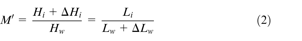
At the loaded state, the actual object dimensions in X and Y directions become
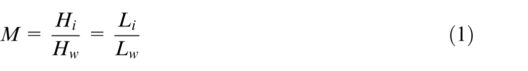
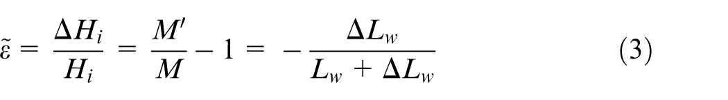
The calculated strains by 2D-DIC could be then estimated as follows
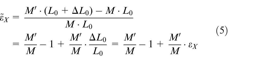
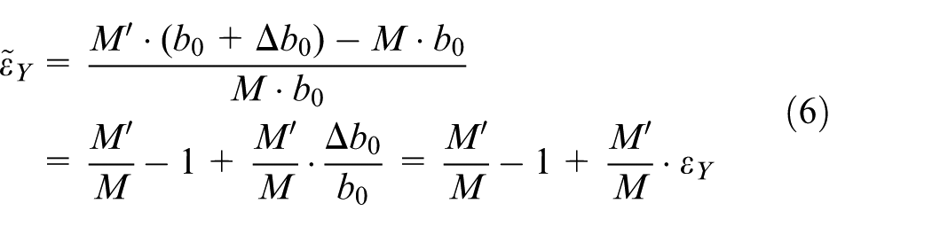
where
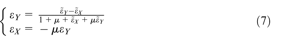
There exist three unknowns,
Experimental verification
In order to verify the “self-correction” method, a uniaxial tension test was conducted on a universal material testing machine, where random out-of-plane displacement occurred to the grips during loading. Two undeformed reference plates of stainless steel were set to compare the “self-correction” method with the reference-correction method proposed by Pan et al. 11 As shown in Figure 2, the reference plate named “Ref-CT” was fixed together with the specimen by two pairs of magnetic iron, while the reference plate named “Ref-LT” was connected to the specimen on one end and fixed on the other end by a pair of magnetic iron. The magnetic iron not only keeps the reference plates in the same plane as the specimen but also allows the axial slippage between the specimen and the reference plates ensuring the reference plates free of load.
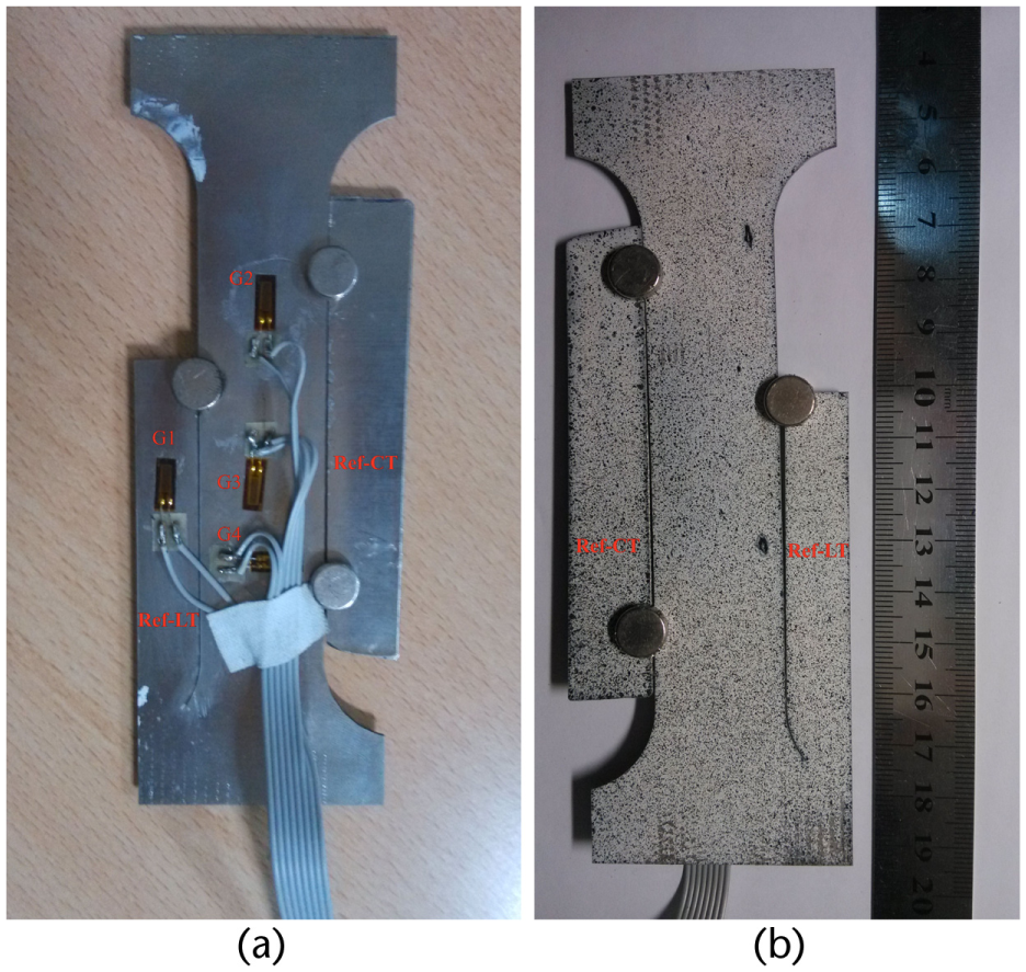
Test plate with two reference plates (labeled as Ref-CT and Ref-LT).
In order to evaluate the accuracy of corrected strain values, four strain gauges were adhered in the middle of the opposite side to the speckle patterns. As shown in Figure 2, two strain gauges (G-2 and G-3) were attached to the specimen in the axial direction to monitor the axial strain, and one strain gauge (G-4) was attached in the transversal direction to monitor the transversal strain due to Poisson’s effect. In addition, one strain gauge (G-1) was attached on the Ref-LT to make sure no deformation there.
The experimental setup was schematically shown in Figure 3. The digital single lens reflex camera (Canon 600D, EF-S: 18–55 mm f/3.5–5.6 IS II lens) was employed to acquire digital images of 5150 × 1717 pixels. The image correlation analysis was performed employing a commercial software named XJTU DIC. The specimen was loaded and unloaded at a constant velocity of 0.1 mm/min for three times. The maximum tensile load was set as 6 kN to make sure the specimen in linear elastic range. At each load/unload increment of 200 N, a digital image and strain gauge data were acquired simultaneously under the control of computer without any pause of loading.
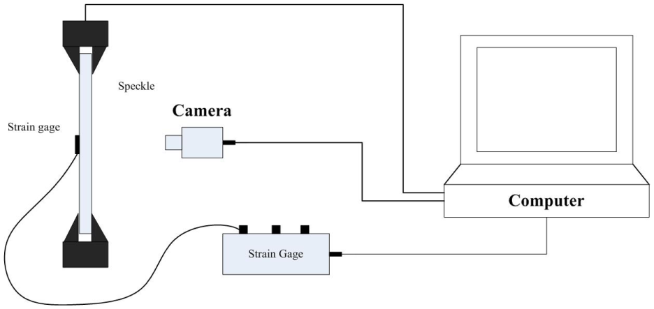
Schematic representation of the experimental setup.
The original axial strains characterized by 2D-DIC without any correction are distinct with the actual axial strains measured by the strain gauges, as illustrated in Figure 4(a). Even the changing trend is different from that of the actual strains, because the out-of-plane motions of the specimen are random. The strains measured by the two strain gauges (G-2 and G-3) are almost the same, demonstrating the reliability of the measured results by these strain gauges. The main cause of the varying strains via DIC is the random out-of-plane motions of the test plates.
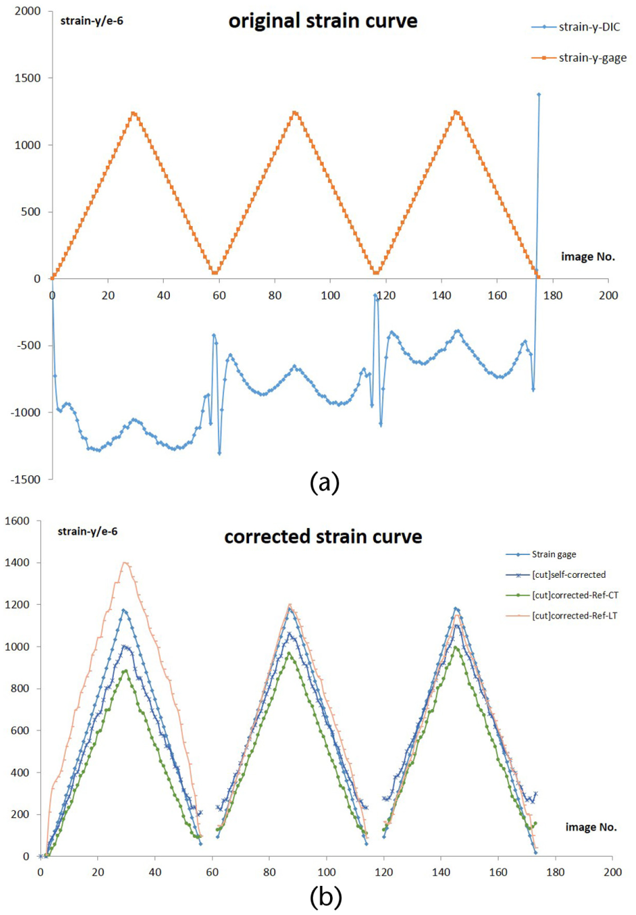
Strain curves obtained by strain gauges and 2D-DIC: (a) before correction and (b) after correction.
The strain errors caused by out-of-plane motions were “self-corrected” and “reference-corrected” employing the DIC-measured strains of Ref-CT and Ref-LT separately. According to the strain data from the strain gauges (G-2 and G-4), a constant Poisson’s ratio of 0.24 was derived, which was employed in self-correction method. As shown in Figure 4(b), the DIC strain curves after corrections are all in good agreement with the actual strain curve. Thus, the proposed self-correction is verified.
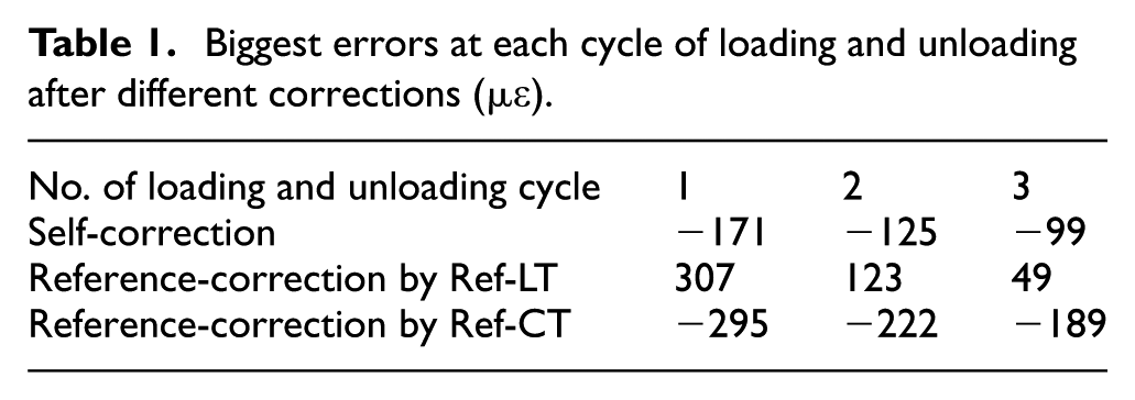
The residual errors of the corrected strains are shown in Figure 5, and the biggest errors after corrections in each cycle are listed in Table 1. The mean error of each correction method is less than 100
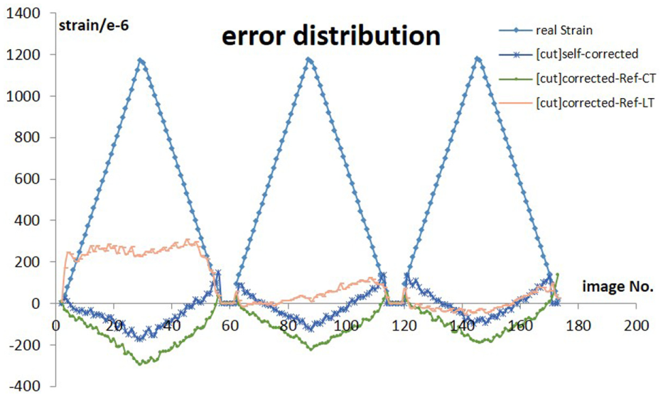
Residual errors after corrections.
Biggest errors at each cycle of loading and unloading after different corrections (
Discussion
The accuracy of self-correction method can be evaluated in theory, based on the principle of error transmission. 13 In experiments, the 2D-DIC-measured strain of the region is estimated as the mean value of all the calculation points in the region. Thus, the error of mean value derives from stochastic error of multiple points measurement. The residual error after self-correction can be approximated as follows
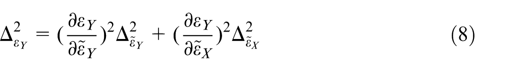
where
Confirmed by the verification experiments and the error analysis, the proposed correction methods are effective to eliminate the strain errors caused by out-of-plane motions, and the post-correction accuracy is close to ideal state accuracy.
Conclusion
2D-DIC is a simple, efficient measurement method applicable to various engineering problems. This study proposes a “self-correction” method to address the unacceptable error due to the unavoidable out-of-plane motions. This method does not require any extra experimental setup, which is simpler than previous published methods. The verification tension test, where random out-of-plane displacement occurred, demonstrated the effectiveness and practical accuracy of the self-correction method. According to the experimental results and the error transmission theory, the self-correction method maintains the analysis accuracy of the DIC software.
We have to figure out that the self-correction method is limited to engineering applications with simple strain distributions to pay the price of simplicity. But this self-correction method enables 2D-DIC to play an important and even unreplaceable role in many engineering applications.
Footnotes
Acknowledgements
Wentao Yan would like to specially thank Professor Xide Li at School of Aerospace, Tsinghua University, for the constructive discussion both in and after his class.
Declaration of conflicting interests
The author(s) declared no potential conflicts of interest with respect to the research, authorship and/or publication of this article.
Funding
The author(s) disclosed receipt of the following financial support for the research, authorship, and/or publication of this article: This work is supported by National Science and Technology Major Project of China (Grant No. 2012ZX04010082) and Independent Research Program of Tsinghua University (Grant No. 2011Z05115).