
Abstract
Tungsten inert gas arc welding–based shaped metal deposition is a novel additive manufacturing technology which can be used for fabricating solid dense parts by melting a cold wire on a substrate in a layer-by-layer manner via continuous DC arc heat. The shaped metal deposition method would be an alternative way to traditional manufacturing methods, especially for complex featured and large-scale solid parts manufacturing, and it is particularly used for aerospace structural components, manufacturing, and repairing of die/molds and middle-sized dense parts. This article presents the designing, constructing, and controlling of an additive manufacturing system using tungsten inert gas plus wire–based shaped metal deposition method. The aim of this work is to design and develop tungsten inert gas plus wire–based shaped metal deposition system to be used for fabricating different components directly from computer-aided design data with minimum time consumed in programming and less boring task compared to conventional robotic systems. So, this article covers the important design steps from computer-aided design data to the final deposited part. The developed additive system is capable of producing near-net-shaped components of sizes not exceeding 400 mm in three-dimensional directly from computer-aided design drawing. The results showed that the developed system succeeded to produce near-net-shaped parts for various features of SS308LSi components. Additionally, workshop tests have been conducted in order to verify the capability and reliability of the developed additive manufacturing system. The developed system is also capable of reducing the buy-to-fly ratio from 5 to 2 by reducing waste material from 1717 to 268 g for the sample components.
Keywords
Introduction
The main advantage of additive manufacturing (AM) compared to traditional methods (machining, forming, casting, etc.) is the implementation of techniques that can be used through the full manufacturing cycle from pre-production to full production as well as reduction in lead time which takes to produce an object (without machining) and cost of the excessive (waste) materials. 1 This technology has been utilized for the manufacturing of net-shaped or near-net-shaped parts. Net-shaped and near-net-shaped phrases are subsequently referred to as just net-shaped manufacturing with minimal scrap. There are two types of net-shaped part processes, which are founded on high-energy sources such as direct laser deposition (DLD) and shaped metal deposition (SMD).2–9SMD method allows complex solid parts to be produced, and it provides a rapid, flexible, and cost-effective way compared to traditional production methods. SMD technology has an ability to fabricate middle-sized and large near-net-shaped fully dense parts.6,7,10,11
SMD processes can be classified as wire plus laser beam, wire plus electron beam, and wire plus arc beam. Wire plus arc AM can be subdivided into three types, namely, as tungsten inert gas (TIG) + metal wire, metal inert gas (MIG) + metal wire, and plasma + metal wire. 12 Nowadays, arc + wire–based SMD technique becomes preferable as compared with other techniques, for example, laser and electron beams, because wire and arc additive manufacturing (WAAM) systems are having low investment cost, there is no need for vacuum environment and are easy to prepare and handle, and there are no reflectivity problems as in laser beam melting. For these reasons, the final costs of the parts to be manufactured will be low as compared to other techniques. The TIG + wire SMD (TW-SMD) technology provides new routes to manufacturing large-scale and high-quality parts with high deposition rates.
The SMD system generally consists of the following main units:
Melting source, which refers to the electrical arc machine or high-energy electron and laser beams;
Deposition metal supplier, which refers to the metal solid wires using wire feeder machines;
Deposition path machine, which may be welding robots, multi-axis computer numerical control (CNC) routers, or any machine which is able to generate the deposition paths;
Control system and software, which enable depositing materials according to the defined path.
TW-SMD requires designing and developing integrated systems which are able to reduce time-consuming and boring task of deposition process. A deposition path machine plays the main role in the SMD technique capabilities; therefore, a large body of the studies was done using complicated systems of six-axis robots linked to a two-axis rotary table. In the literature, previous works7,13 used these complex systems to produce Ti-6Al-4V components with two geometries, namely, cylindrical part and straight walls. They produced round parts using rotating table and holding the torch as fixed, while the wall components were done using the robot’s movements. Studies6,7,14 used the same complicated systems to deposit circular and square Ti-6Al-4V components, while some studies used robotic systems with WAAM to produce walls, squares, and circular components of SS308 alloy.15,16 Some of the studies developed pre-programmed robot systems for WAAM techniques.17–30 Besides, some of them have used special mechanical systems such as four-axis CNC milling machines or three-dimensional (3D)-positioned CNC machines.31–36 In the literature, it was experienced that the integrated systems are really complicated and limited to special codes and machine languages which mean that these systems are considered as closed systems used for generating the deposition paths. Actual robot paths are directly calculated from the computer-aided design (CAD) geometry. There are some of the difficulties which may appear during the deposition process such as producing wall crossing due to the weld beads overlap at the crossing point.
Most of the existing systems begin with a model created on a CAD packages, for example, CAD surface or solid modeler to generate an output file such as Standard Transform Language (STL) file. Then, the STL file is sliced using special format into uniform layers and then these layers consider as path trajectories are used for building the part layer by layer.
Mehnen et al. 17 developed a robot path generation program RUAMROB in MATLAB®. This system contains two main modules: a slicing module and a robot program generation module. The program slices the part and generates the path code for a FANUC robot. Zhang et al. 34 developed a new interface between the modeling data and the deposition machine based on the Initial Graphics Exchange Specification (IGES) format CAD model. They used MIG welding as a deposition method. Heralić 36 developed a robotized laser metal-wire deposition system. This system can slice the CAD model into layers of uniform height using LabVIEW format. Bonaccorso et al.19,23,24 designed and implemented a user interface to investigate the control on process stability using LabVIEW format. They used feedback controller to control on the bead geometry. The work of Ribeiro et al.37,38 introduced a new fabrication approach by developing a manufacturing system for Royce plc. Their system was capable of creating solid metal parts directly from CAD models.
All previous studies used CAD packages to create the part’s shape and then creating a program to read these CAD files and transform them into a robot program. The TIG welding–based metal deposition process requires a special interface between the modeled data and the deposition system. Hence, the interface must allow the process parameters to be controlled and tuned during the online deposition process, which is difficult to obtain using the systems depending on the off-line programming (OLP) method.
In this work, a workshop size SMD system was developed in order to produce solid dense parts with minimum materials. In this system, a computer-aided metal deposition machine (CAMDM) was designed, constructed, and controlled only for the purpose of the TW-SMD process which was integrated with TIG welding machine and wire feeding mechanism to study the whole process parameters and produce net-shaped or near-net-shaped products. The CAMDM control system was also genuinely designed to have an open-source controller board type, which gives the deposition process flexibility to develop and edit the operation program and allows controlling and tuning of the process parameters during the online deposition process. Furthermore, the intent of this work is to address the reducing or eliminating the time-consuming of programming, which is consumed in teaching pendant, CAD packages, slicing format programs, and path generating of the robot. All these programs are replaced by the new control program of CAMDM system.
Experimental setup and materials
CAMDM system overview
A three-axis machine was designed and fabricated for the purpose of facilitating the SMD. At first, a feasible design for the proposed SMD machine was prepared. The design was performed according to the valid standards. The CAMDM system is actuated by three stepper motors, which are connected along the x-, y-, and z-directions. The maximum working envelope was designed to be 400 × 400 × 400 mm3. A two-dimensional (2D) mechanical motion of the x–y plane is used to define the geometry of each layer, and the third axis is affected by pulling the deposition tool (DT) up vertically in the z-direction. The substrate is mounted on the work table, whereas the DT is coupled to the z-table of the machine as shown in Figure 1.
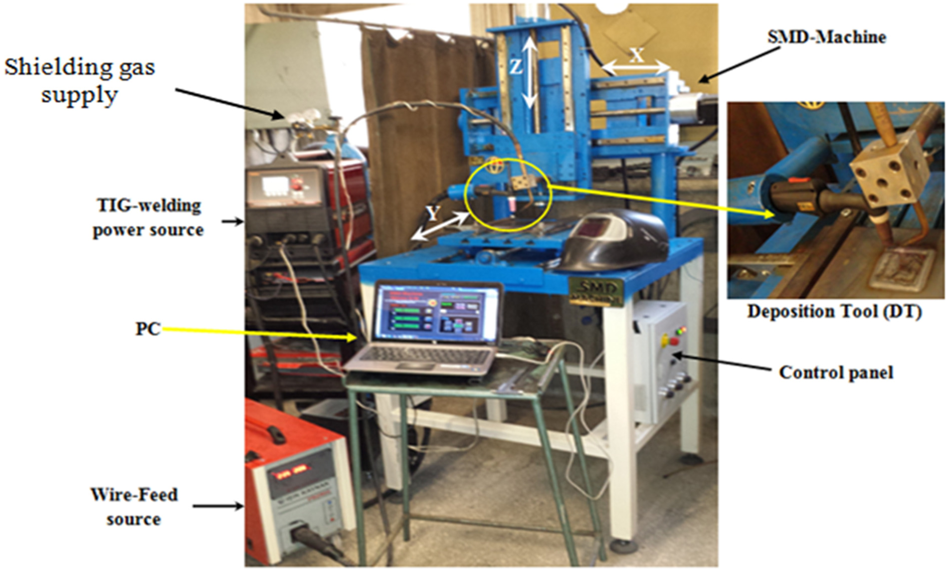
Overall view of the integrated SMD system, showing the close-up view of the deposition unit.
The designed CAMDM is used together with other parts of the SMD system to construct an integrated work cell. The heat source is a constricted arc, and it was conducted using water cooled LINCOLN V320-T AC/DC welding machine. It can supply welding current in the range of 5–320 A, and pulse frequency is between 0 and 2500 Hz. The TIG torch is LincTorch (LT18W) water cooled duty cycle 100%, 1.8-cm cup size with 2% throated tungsten. The tungsten electrode distance from the tip point till the ceramic cup is recommended to be between 4 and 9 mm. 39 Deposited material is supplied by a cold wire which is fed into the melting zone through an annular feed nozzle connected to PROMIG (4T) wire feed machine. It independently provides the cold wire to the DT, and it can be manipulated manually. The DT was coupled to the gantry part of the CAMDM through using special fixtures. The fixtures are responsible for positioning the deposition unit in the desired positions. They allow to tune the feeding angles and feeding directions in order to obtain a stable process.40–42Figure 1 shows the overall view of the CAMDM and other SMD integrated system.
In the present SMD system, online programming method utilizes 3D CAD data of a part to generate and simulate the CAMDM programs. Online programming is selected since it has low cost compared to the OLP package, especially for smaller product volumes. OLP software is time-consuming and requires high-level programming skills, but, however, online one is less complex than the OLP. 43
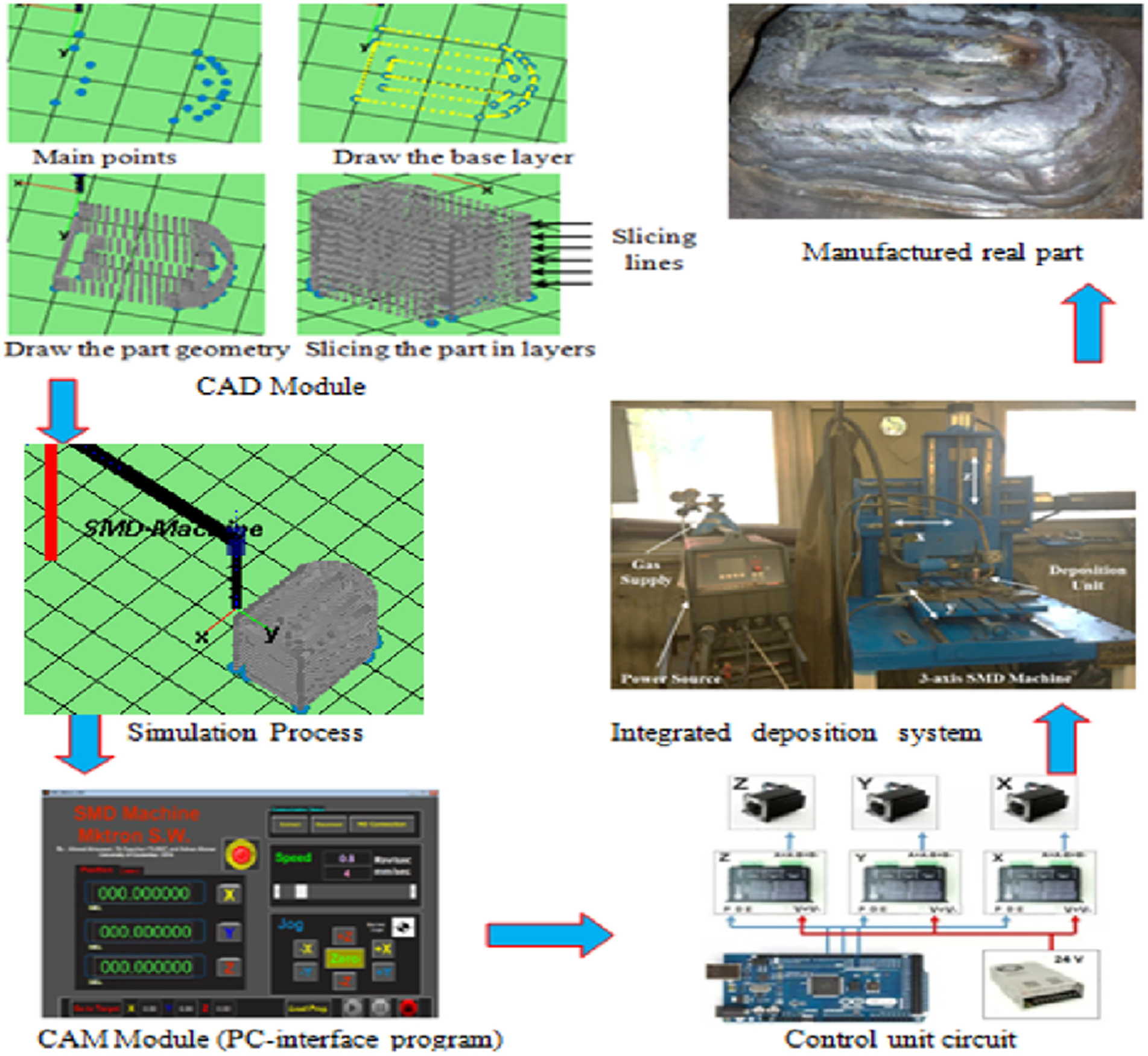
The CAMDM control system has a novel program which was created by MATLAB software. The program allows drawing the CAD model of the part in MATLAB instead of using commercial CAD packages. The CAD drawing can be created in such a way that the main points of the geometry which are necessary to give main corners and sharp edges in the part are defined, and the program will complete the establishment of the part in point-to-point method. At the same time, the program slices the drawing directly from the base layer toward the top depending on the amount of the selected layer thickness and the number of the layers. These layers represent the path trajectories to be used in the computer-aided manufacturing (CAM) program. Figure 2 illustrates the overall control of the CAMDM system.
Main units, integrated into the CAMDM system.
Before the actual deposition process in CAMDM, the deposition paths must be simulated and tested in the control software in order to show and verify the motions that are applicable to the equipment (see Figure 2). The SMD machine was constructed using three-axis Cartesian coordinates which are in (
The CAMDM path generation has been created in MATLAB. The developed CAD module has abilities to do following activities:
Creating the configuration of the part to be fabricated by introducing the important points of the part;
Slicing the part into selected height layers;
Building the sequence of the path through slicing the CAD model into ISO-line paths;
Choosing the suitable path trajectory, which is either LINE program or ZIGZAG program;
Choosing deposition method whether it is a continuous or discrete strategy;
Finally, simulation process created.
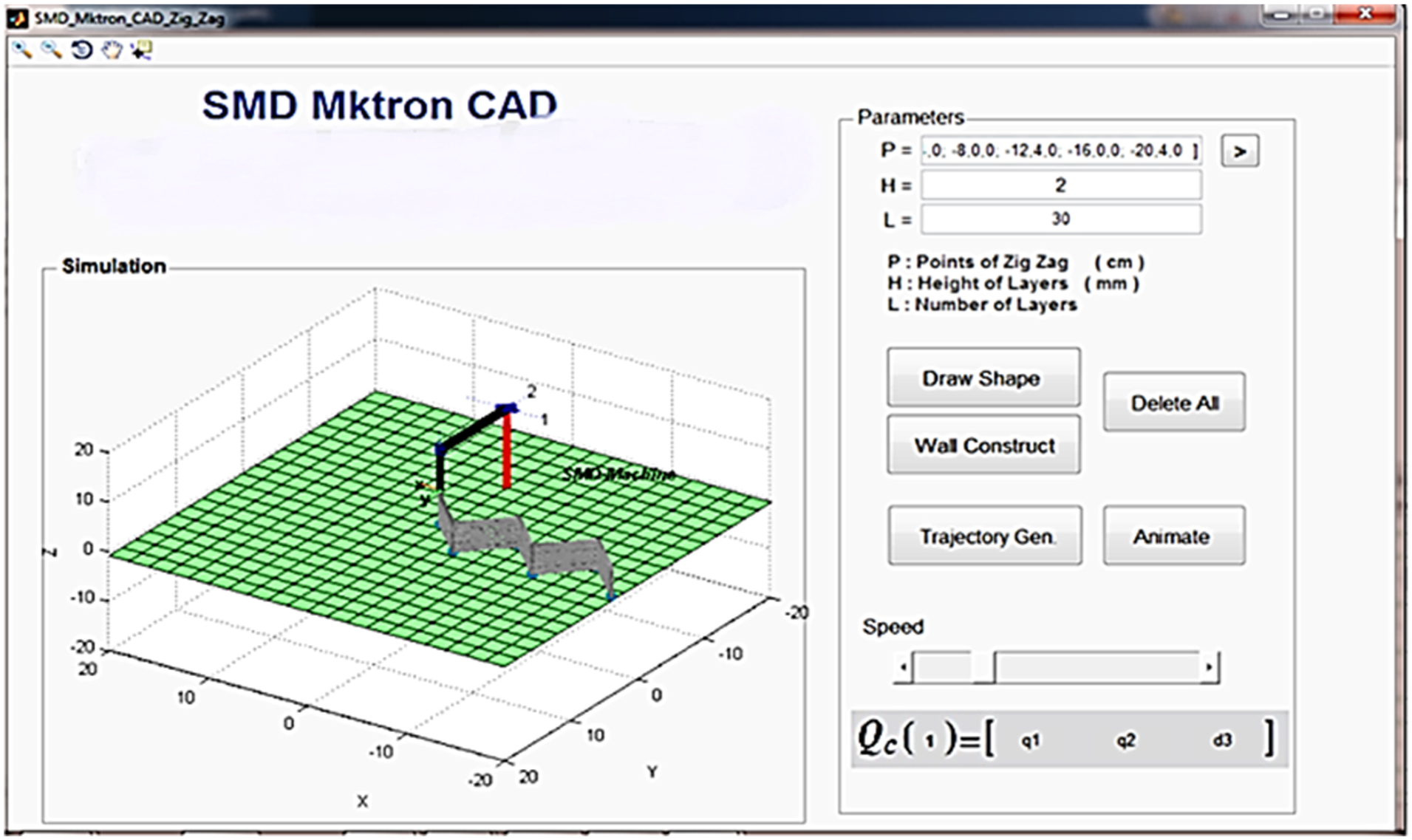
CAD drawing is first transformed by a graphical user interface development environment (GUIDE) program to be input to the user interface after building a sequence of the part. The operator can define the main points of shape, layer height, and the number of layers as shown in Figure 3. Afterward, a translational transform between points is created (x–y path), and the layers are built by increasing z-axis by layer height for the x–y path. The pattern model is expressed as points in 3D. The pattern points can be saved as m-file, and it can be loaded on the machine user interface program for the implementation. The paths can be translated into STEP format and uploaded into the system controller. The CAMDM program receives the CAD output file and converts it to the low-level machine code (G-codes).
Control screen of the CAMDM system.
The architecture of the block diagram used for studying and controlling the deposition process is constructed by PC interface program, control unit, and SMD machine as shown in Figure 2. The PC interface program is a user interface panel. It is an advanced CAM program, which is used for controlling DT movements, speeds, and directions relative to machine workspace. It is projected with the GUIDE of MATLAB. This software is practiced because of the system requirement to play at the online process that is supported by MATLAB real-time signal processing.
The control unit is constructed to receive commands from computer programs and send the current position of the machine axis as a feedback. The control unit has an open-source simple microcontroller board (Arduino Mega 2560) and drivers of the motor. The open-source program is a low-level program, which gives the CAMDM as flexibility to develop and edit the operation program. The user can easily control the machine manually by JOG, apply machine zeroing, monitor the change of the parameters of the machine, and load sequential program model.
The control system was designed and programmed only for the CAMDM axis movements. A general hardware structure of the SMD system is shown in Figure 4. The dotted arrows represent the ideal situation work cell.
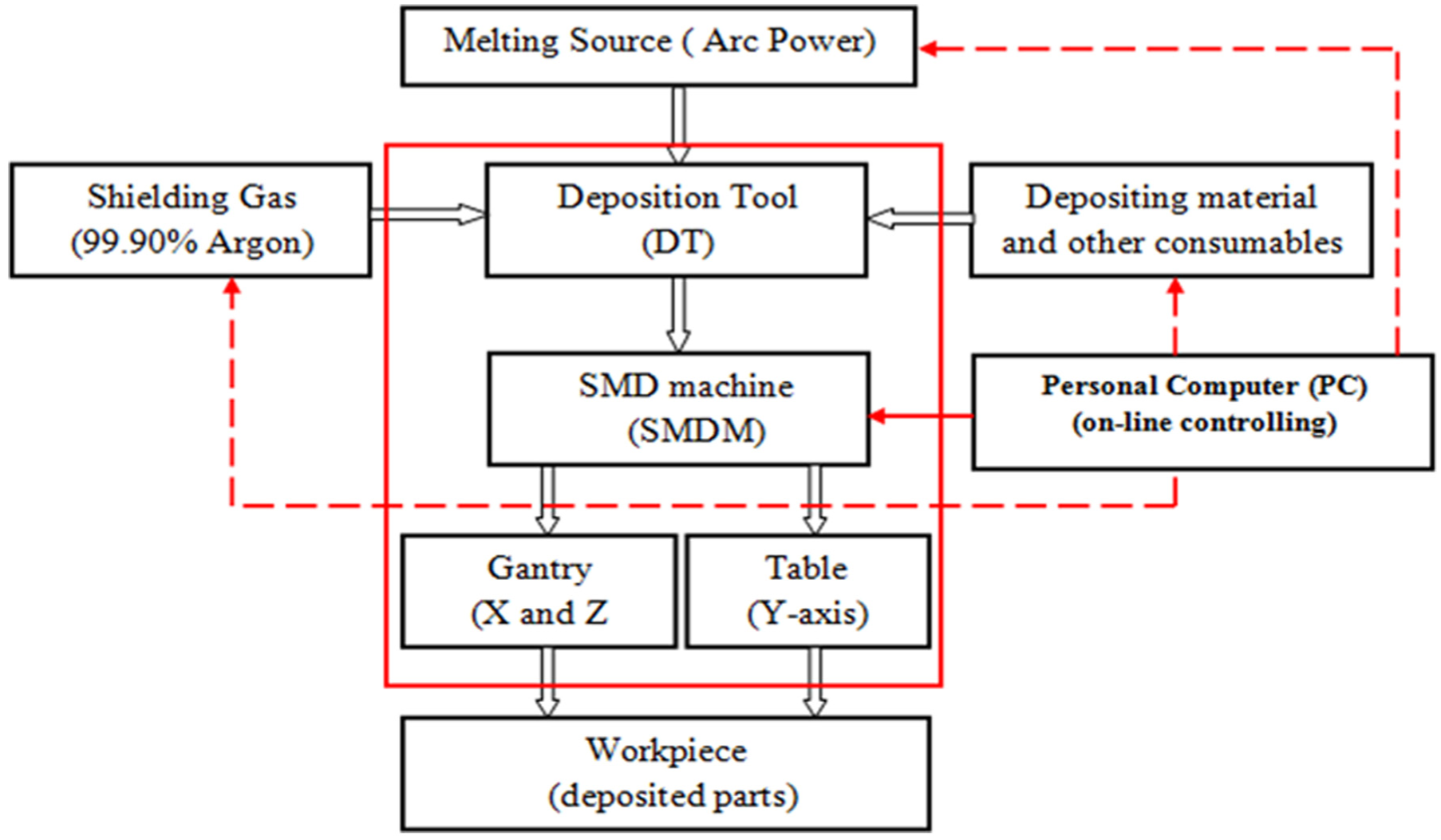
Work cell structure in SMDM hardware.
Materials and experiments
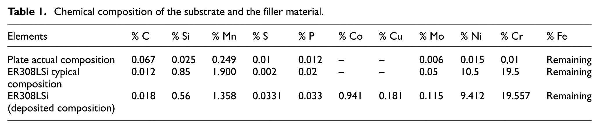
The substrates used in this work were plates of rolled low carbon steel substrates type St. 3 according to Deutsches Institut für Normung e.V. (DIN) standard. 44 Substrates were with dimensions of 100 × 200 × 6 mm3 and 200 × 250 × 6 mm3. Substrates were placed on the SMD machine table and strongly clamped to the fixture in order to avoid deformation and increase the dissipated heat. The filler material used for the depositing process was a stainless steel solid wire of 0.8 mm in diameter. Its grade and specifications were chosen according to AWS A5.9-95 specification so that the wire grade is ER308LSi. 45 Table 1 shows actual laboratory results of chemical composition (wt%) of the substrate and deposition material. The inert gas was 99.90% purity Argon with 12 L/min flow rate applied from the top side to protect the deposition zone from the oxidation and other contaminants during the deposition process.
Chemical composition of the substrate and the filler material.
Prior to the deposition, it is necessary to carefully tune the main process parameters and conditions, such as arc current (I), arc length (L), travel speed (TS), and wire feed speed (WFS) as well as other conditions such as wire feed direction, wire feed angle, and substrate temperature (interpass temperature). These parameters and conditions play a vital role in the deposition process stability.
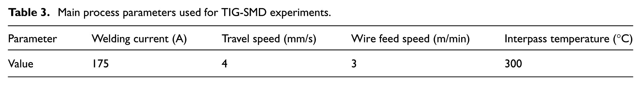
Several preliminary experiments were carried out in order for tuning the main parameters and conditions and hence identifying their limits and understanding their effects on the bead geometry and process stability. All the experiments were conducted without using a chamber (no inert gas chamber). From those preliminary experiments, the suitable set of parameters that make the deposition process more stable is listed in Tables 2 and 3.
Constant conditions of SMD process.
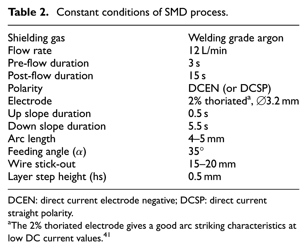
DCEN: direct current electrode negative; DCSP: direct current straight polarity.
The 2% thoriated electrode gives a good arc striking characteristics at low DC current values. 41
Main process parameters used for TIG-SMD experiments.
In order to verify the developed CAMDM system, well-designed experiments were conducted. To do this, various designed components such as tubular-shaped parts, hollow features, solid parts, and other features of single stringer multilayer walls were chosen. These are typical features used in the aircraft structures resembling such as the rib -web components and other stiffened panels with crossings. Such featured parts are traditionally manufactured with the buy-to-fly (BTF) ratios of 10–20:1. 46
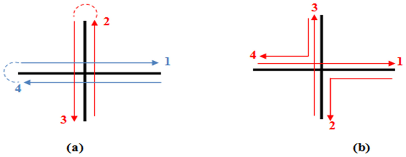
Mehnen et al. 17 investigated the possibility of producing different designs of these stiffened panels using the MIG welding-based SMD technique associated with the robotic system. They showed that there is the difficulty of producing this feature due to the built peaks where the weld bead overlaps at the crossing points. So, they used a path pattern of opposite angles as shown in Figure 5. In this work, the developed CAMDM is more flexible and hence allowing to overcome the aforementioned problem in the cross wall feature of the stiffened panels since the control system of the CAMDM is designed to be the open-source system which allows the DT to position and move accurately. This system also enables the operator to control and tune the input parameters during the deposition process and hence adjust the process immediately. Two alternative patterns are prepared to deposit the cross wall feature as shown in Figure 6. The pattern in Figure 6(b) is the most suitable one since it leads to reduce the total deposition time, produce each layer with one arc ignition and can continue for the sequential layers, make the deposition process more stable, and eliminate the peak from the overlap pattern. Figure 7 shows the CAD drawing and the real deposited crossing wall component.
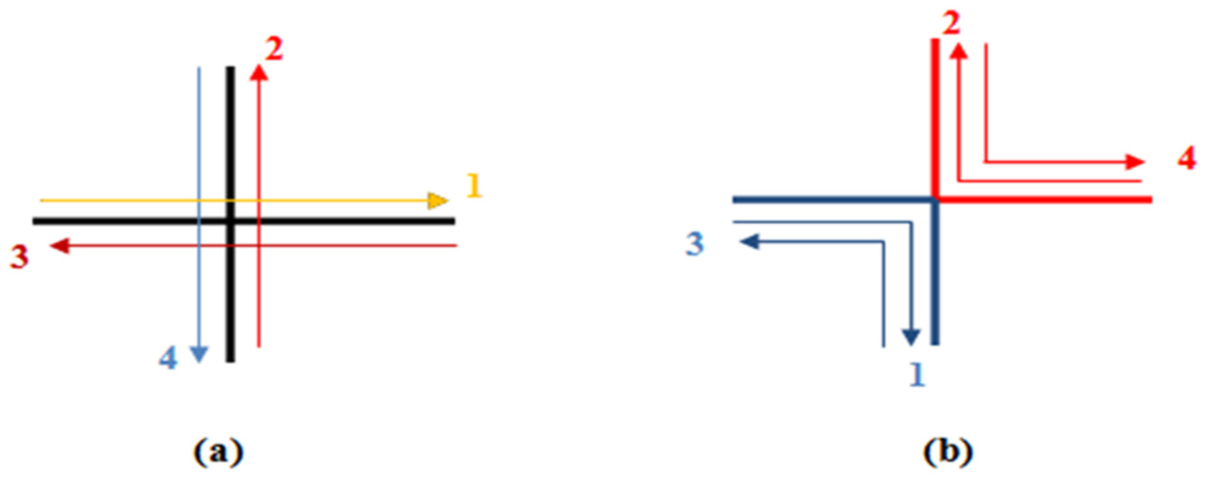
Deposition patterns of cross feature: (a) overlap pattern and (b) opposite angle pattern.
Deposition patterns of cross wall feature: (a) overlap with two start ends of the arc and (b) overlap pattern with continuous ignition arc.
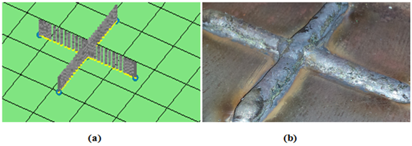
Example of crossing wall feature produced using the continuous ignition arc: (a) CAD drawing and (b) deposited part.
The hollow features can be fabricated using the CAMDM system by the main types of path patterns, that is, spiral pattern and zigzag pattern. In order to demonstrate the two types of the path patterns, the deposition of the hollow rectangular part was carried out by both the spiral pattern and the zigzag pattern. The deposition starts from the upper right side and completes the outline of the part configuration and then using either the spiral or zigzag movements to complete the filling of the first layer of the deposited area, thereafter reversed direction for deposited sequential layers and so on. Figure 8(a)–(c) shows the Shaped Metal Deposition Machine (SMDM) path procedure used to produce the hollow filling area of the square part. Figure 9(a) and (b) shows another path pattern used to produce this part. The real deposited layer is shown in Figure 9(c). Furthermore, the CAMDM system is ready to create the solid filling area features. In order to show the two types of the path patterns, the deposition of the solid circular feature part was carried out by both the spiral pattern and the zigzag pattern, as shown in Figure 10(a) and (b), respectively. Figure 10(c) presents the first few layers of the real deposited part manufactured using zigzag path pattern.
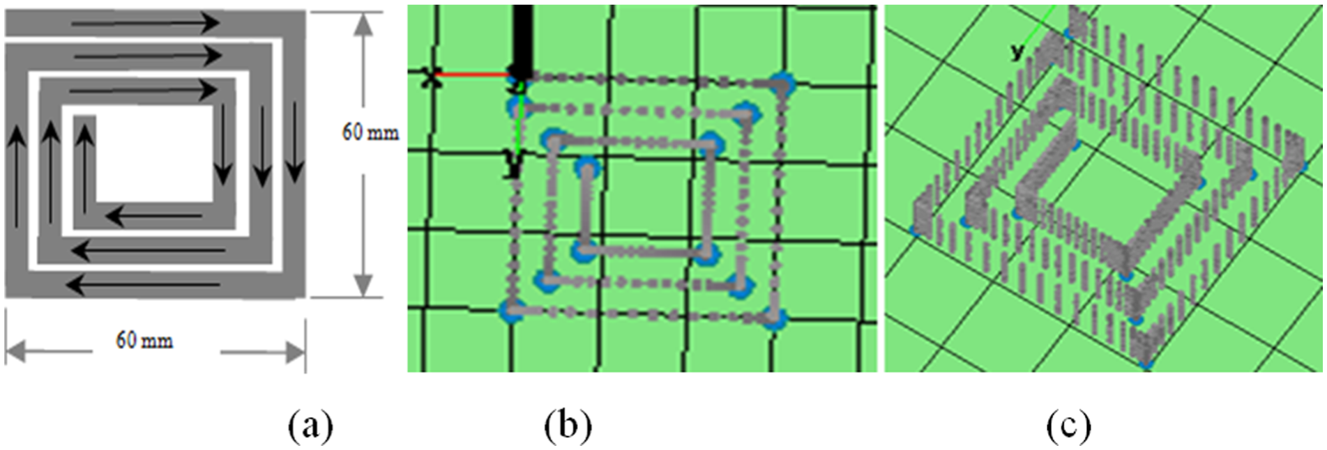
Spiral path pattern for hollow filling rectangular part: (a) spiral path pattern and (b and c) the CAD drawing and layer slices.
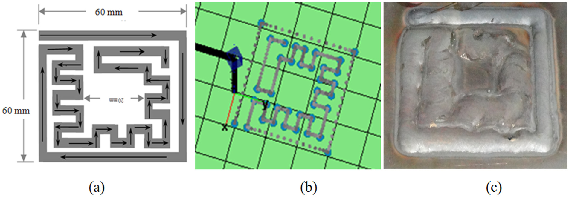
Deposition of hollow filling rectangular part: (a) contour and zigzag/raster path pattern, (b) the CAD drawing, and (c) single deposited layer using the TW-SMD method.
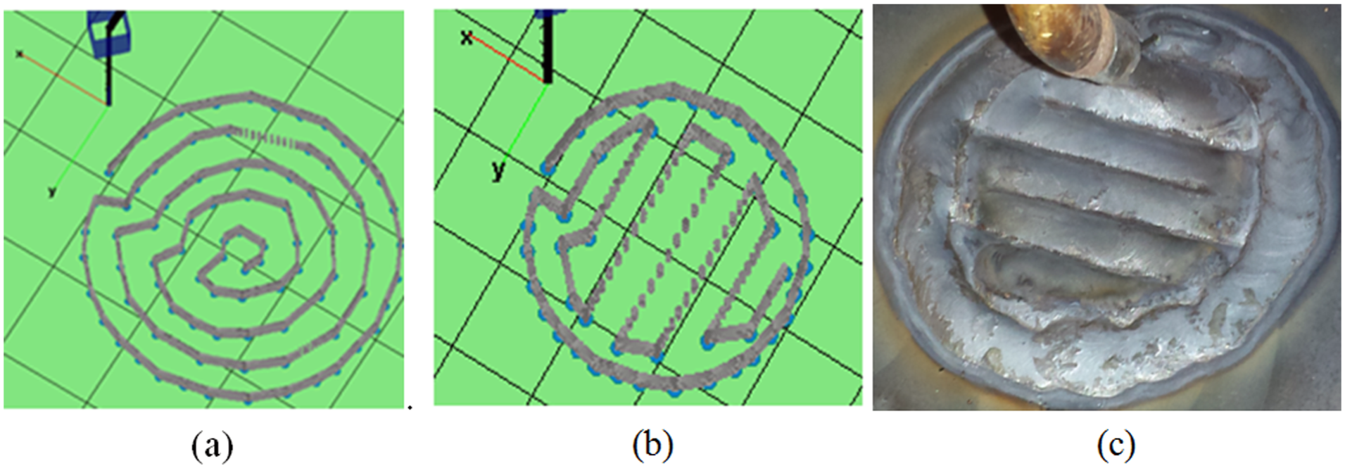
Combined path pattern for solid filling cylindrical part: (a) CAD drawing of the combined path pattern by spiral strategy, (b) CAD drawing of the combined path pattern by zigzag/raster strategy, and (c) the first deposited layer using the zigzag/raster pattern.
Results and discussions
SMD post-processing
The control system used in the SMD machine is a feed forward (open-loop) control type. Post-processing covers 3D object modeling based on CAD drawing, planning, and slicing of the pattern in uniform thick layers. The CAD drawing is imported using an online programming method. So, the desired geometry according to the CAD specification is sliced into layers of uniform height. For each layer, the paths along which the beads should be deposited fill the layer. 42 The deposition process has been established with an interface between the modeling data and the DT. This was done by slicing the complicated 3D geometry into simple 2D features and designing of the CAMDM paths and deposition parameters. The flowchart of the deposition post-processing of the developed system is described in Figure 11. Using the CAMDM control program, there is no need for CAD packages and other programs which may be used for generating the motion paths. These packages and formats usually have some of constraints and compatibility problems in file format and design limits. Furthermore, some of the slicing formats which are used for slicing the STL files are limited to slice the very complicated CAD drawings. In other robotic systems, in the case of adding further hardware to the system, there is a difficulty in inserting it in the machine codes of the robot control unit. In other words, the new hardware becomes restricted by the ready robotic packages. While the CAMDM system program was designed to be applicable for expansion and development since it has an open-source system. In addition, the CAMDM software has the flexibility to choose the suitable deposition path method, so that for the square, circle, and all polygon features, the continuous path trajectory is used. While for wall, curves, and all discrete features, the reversed path trajectory is used.
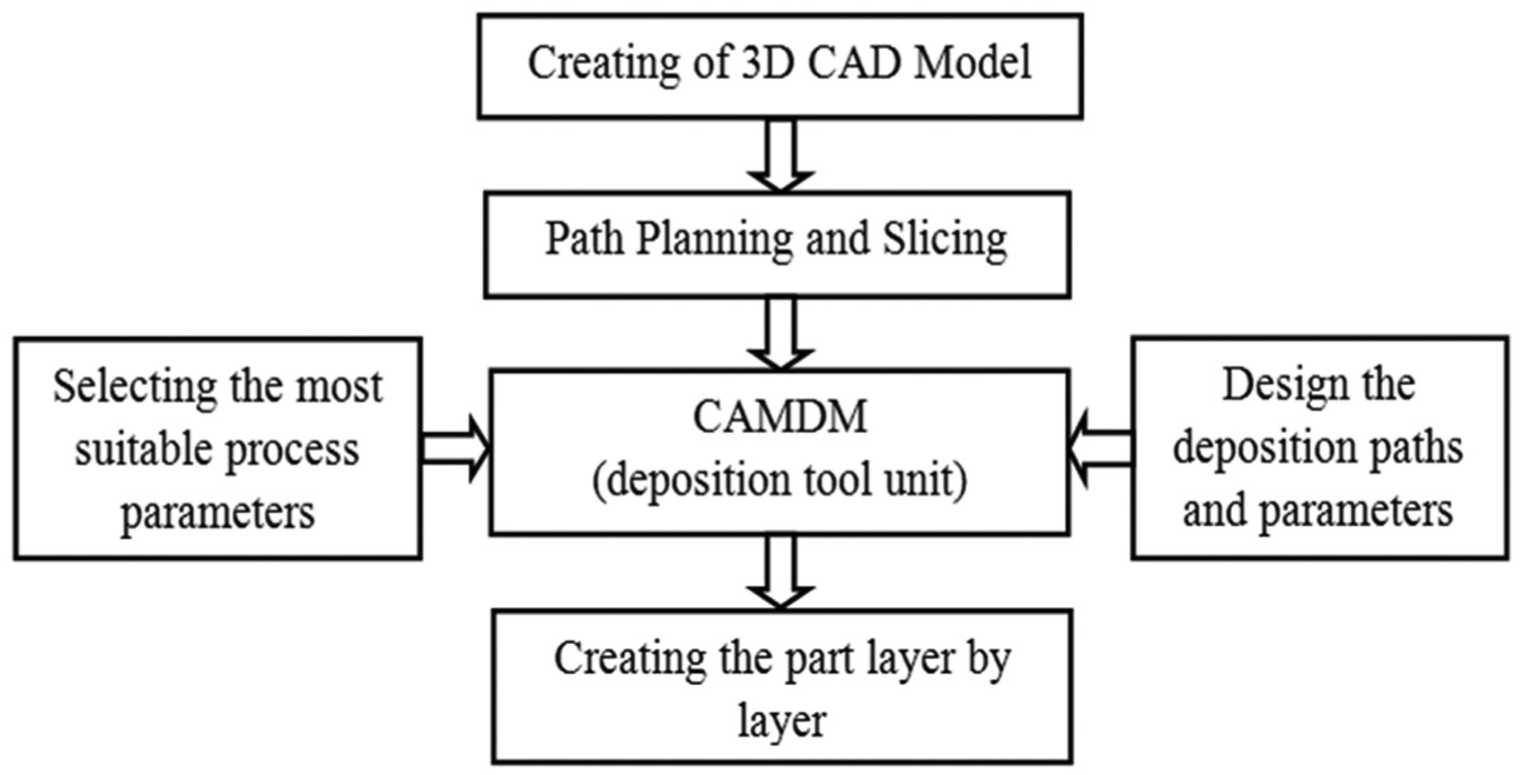
Building part flowchart in CAMDM system.
CAMDM capabilities and limitations
Due to the physical nature of the present system and the control system is an open-source one, the present system is capable of manufacturing the stiffened panel features, especially the crossing wall, without difficulty such as building up the peaks at the overlap of the crossing points. Several experiments were conducted, and in these experiments, different parts were deposited in a solid filling area, a hollow filling area, and also tubular featured parts using the developed interfacing technique.
It is important to be mentioned that there are some limitations of the TW-SMD additive technology and the presented CAMDM system such as path strategies since not all configurations can be fabricated by this technique. For instance, this manufacturing technology is unable to produce complex featured parts which contain side holes or the small features of several millimeters due to the physical nature of this process. Additionally, poor surface quality is mainly generated by tessellation of the original CAD model and slicing during the SMD process. Therefore, the components fabricated by SMD techniques when compared to other conventional manufacturing processes can be inferior in terms of surface quality. Therefore, the parts might need to have finishing processes for the final dimensions either by machining or other types of material removal processes. Furthermore, the wire feed directions and wire feed angles have a significant effect on the building wall geometry and hence the surface quality. Moreover, the cumulative heat that develops during the successive layers usually affects the built dimension. Therefore, this process sometimes needs to idle time for dissipating the excessive heat. The present system allows correcting the main parameters in order to reduce the developed heat during the deposition process without stopping for cooling.
Case study
The developed SMD system was effectively used to fabricate a solid and dense aerospace part, which may be produced using traditional methods. The aerospace part has a special configuration similar to omega shaped (O) was chosen for comparing the TIG-SMD and another conventional method, that is, material removal process (machining) in terms of production time, waste metal in percentage, and the BTF ratio.
A comparative experiment of the current system and traditional machining processes
The developed SMD system can be used to produce different geometries without major difficulties which can be encountered in other systems, for example, robots and computer-controlled machines because of the fact that it depends on the open-source system, which gives the operator having a capability to tune the process parameters and control the DT movements during the deposition process and gives the system more flexibility to produce different geometries. So, it is possible to claim that the current SMD system is appropriate for workshops working on fabricating small- and medium-sized parts as well as repairing metal dies/molds.
Finally, an aerospace part geometry was selected as a case study in order to evaluate the cost and time savings using TW-SMD and provide an idea about the benefits of developed technique. The sketches shown in Figure 12(a) and (b) illustrate the dimensions of the required part. The experimental procedure consists of the steps that were aforementioned in Figure 2. The height of the deposited part was achieved after 48 layers. The average dimensions of the as-deposited part are shown in Figure 13(a), whereas the final part after finishing the process of the deposited part is shown in Figure 13(b). Total time consumed during deposition of each layer of the part was 53 s. So, the total deposition time was measured as 42.4 min. Whereas the machining time consumed during finishing the part is 32 min. Figure 14(a) shows the total production time for manufacturing the finished parts by TW-SMD and traditional milling machining processes. It is obvious that the TW-SMD takes longer time than milling machine since the part has simple features. However, the TW-SMD process produces a waste metal percentage less than that of the traditional method as shown in Figure 14(b).
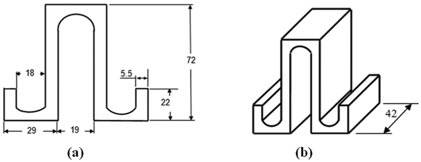
(a) Sketch illustrates the cross section of the final part after finishing processes and (b) sketch shows the isometric view of the part (all dimensions in millimeter).
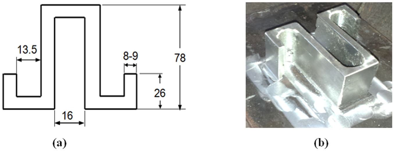
Sketch shows (a) the real deposited part dimensions after deposition process and (b) shows the real deposited part after machining process (all dimensions in millimeter).

Plots illustrate the comparison of the manufacturing methods versus (a) the production time and (b) waste metal percentage.
Another comparison between TW-SMD and traditional machining methods was done by calculating the BTF ratio. BTF ratio is often referred to within the aerospace community to establish the amount of material needed to purchase in order to manufacture the final “flying” part. BTF is a weight ratio between the raw material used for a component and weight of the component itself. 22 Traditional machining methods typically produce components with BTF ratios of 5:1 but sometimes >20:1 due to the large amount of waste and difficult-to-recycle material. 47
Figure 15 shows an example of a comparison of the BTF ratio between traditional machining method and the developed TIG-SMD system. The finished part has a weight of 450.748 g, and the weight of the forged billet which requires producing the part by machining has a weight of 2168.1 g, thereby this gives a BTF ratio near 5. This method is extremely wasteful in terms of material. Conversely, using TW-SMD technique, the deposited part has a weight of 718.725 g as a cold wire which is added with 267.977 g machined away to obtain the finished part geometry. This method provides a BTF ratio of near to 2 and saving materials of 1446.655 g. The CAMDM system can reduce about 84.4% of the waste material which means that it can save about 66.7% of the raw material used according to the following relations:
Reduction percentage of the waste material = 1446.655/1717.352 = 84.4%;
Saving percentage of the raw material = 1446.655/2168.100 = 66.72%.
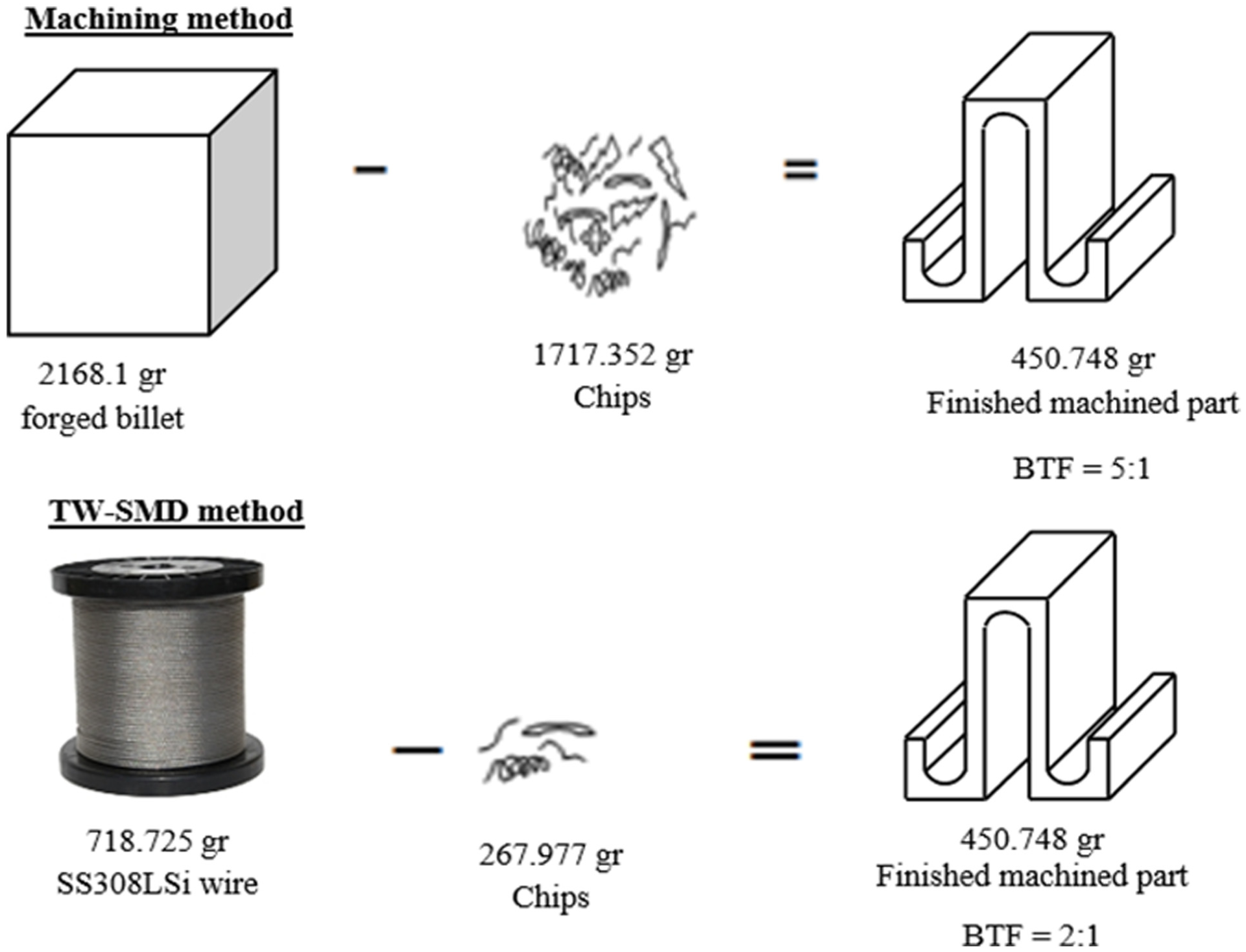
Comparison of traditional machining process versus SMD process in terms of BTF ratio.
Conclusion
In this study, a cold wire feed additive layer manufacturing SMD system was developed to produce fully dense near-net-shaped parts. The CAMDM system was constructed in the manner of reducing the need for slicing strategies for STL files since the present system directly draws, slices, and simulates the part’s drawing using the same CAD module. So, it reduces the efforts and tedious tasks necessary for robots and also shortens the time of teaching the trajectories. The major conclusions are summarized as follows:
A new type of SMD system was designed and constructed in this work. The results showed that the developed CAMDM system is easy to use for manufacturing near-net-shaped parts.
Online programming which is more suitable for CAMDM was used. This type of programming gives the system more flexibility to control the process parameters, and it is less complex than the OLP.
An open-source software was designed for CAMDM to be applicable for expansion and development. It allows tuning the main process parameters during the deposition process, that is, reducing the input power or increasing the TS, and thus, the cumulative heat input through the deposited part could be reduced to a limit that does not cause the flow of the molten metal. This procedure improves the surface quality of the deposited part and eliminates the long idle times which could be necessary after each few layers. This causes in increasing the productivity.
The developed CAMDM system is capable of producing various solid filling parts, hollow filling parts, and another single stringer where discrete and polygon features in near net shaped with satisfactory quality components of sizes do not exceed 400 mm in 3D.
From the comparison results, it was discerned that the current CAMDM system is capable of saving about 66.7% of the raw materials as compared to the conventional machining methods by achieving BTF ratio of 2:1 but with longer production time.
Footnotes
Declaration of conflicting interests
The author(s) declared no potential conflicts of interest with respect to the research, authorship, and/or publication of this article.
Funding
The author(s) disclosed receipt of the following financial support for the research, authorship, and/or publication of this article: This research was performed with financial assistance (Grant No. MF.14.29) from the Scientific Project Bureau of University of Gaziantep.