
Abstract
Higher tool wear and inferior surface quality of the specimens during machining restrict metal matrix composites’ application in many areas in spite of their excellent properties. The researches in this field are not well organized, and knowledge is not properly linked to give a complete overview. Thus, it is hard to implement it in practical fields. To address this issue, this article reviews tool wear and surface generation and latest developments in machining of metal matrix composites. This will provide an insight and scientific overview in this field which will facilitate the implementation of the obtained knowledge in the practical fields. It was noted that the hard reinforcements initially start abrasive wear on the cutting tool. The abrasion exposes new cutting tool surface, which initiates adhesion of matrix material to the cutting tool and thus causes adhesion wear. Built-up edges also generate at lower cutting speeds. Although different types of coating improve tool life, only diamond cutting tools show considerably longer tool life. The application of the coolants improves tool life reasonably at higher cutting speed. Pits, voids, microcracks and fractured reinforcements are common in the machined metal matrix composite surface. These are due to ploughing, indentation and dislodgement of particles from the matrix due to tool–particle interactions. Furthermore, compressive residual stress is caused by the particles’ indentation in the machined surface. At high feeds, the feed rate controls the surface roughness of the metal matrix composite; although at low feeds, it was controlled by the particle fracture or pull out. The coarser reinforced particles and lower volume fraction enhance microhardness variations beneath the machined surface.
Introduction
Since 1950s, engineering materials with different industrial potentials such as, medical, aerospace/aircraft, defence, automotive and sport equipment sectors have significant improvement when materials with low density, high strength-to-weight ratio, higher wear and temperature resistance and high hardness were introduced.1–3 Composites, known as the ‘materials of the future’ in nineteen-seventies, are one of them 4 which play an important role in efficient and improved application of engineering materials.5,6
Metal matrix composites (MMCs) are part of the composite materials that demonstrate improved and expected material properties.4,7–10 MMCs are made of metallic matrixes, such as aluminium, magnesium, titanium, copper and their alloys, which are reinforced by stiff and hard ceramic phases, such as Al2O3 and SiC. The desired properties in MMCs are obtained by manipulating the matrix, reinforcement and their interface.11–14 MMC components with preferred shapes, finish, dimensions and tolerances are required for any practical applications. The required shape of the MMC products is produced by bonding, powder metallurgy, brazing, casting, metal spraying and forming operations like extrusion, bending, swaging and drawing. In addition to good surface finish, accurate dimensional tolerance should be gained for high-tech applications, 15 which is always associated with machining for shaping composites into engineering products.16,17 Therefore, understanding of surface characteristics produced by machining has enormous influence on composite material applications in precision engineering or assembly operations, as the surface quality during machining determines its ability to handle severe conditions such as stress, temperature and corrosion which influence the longevity and reliability of composite products.18,19 It is reported that machining of MMCs is significantly more difficult than those of conventional materials because of the existence of harder and stiffer particles as reinforcement in matrix. 20 These particles increase the tool wear and surface roughness of the work specimens.21–23 Increased cutting tool wear severely affects machined surface quality and integrity. Worn tool fractures and debonds higher percentages of reinforcement phases during machining.24–28 For instance, failure of the cutting tool results in workpiece surface’s deterioration, loss of geometrical tolerances and other catastrophic consequences, like an enhancement in the downtime to change and set the tools. 29
The surface characteristics affect the performance of composites’ product. Two factors have main effect on the machined surface quality: surface topography and subsurface integrity. 30 The surface integrity achieved by final machining directly affects the quality and performance of a product. 31 Surface integrity comprises workpiece metallurgical (phase transformation, microstructure and related property variations) and mechanical (residual stresses, hardness and so on) properties and its topological parameters (surface finish and other characteristic surface topographical features).32,33 Different parameters can affect the machined surface’s quality and integrity, which depend on the workpiece, tool and process-related parameters employed during machining. Feed rate, depth of cut (DOC), cutting edge geometry, cutting speed and tool nose radius have influence on the performance measures like surface roughness, cutting forces, subsurface damage, microhardness and surface residual stresses induced in the machined surfaces on composites. Machining parameters have effect on surface integrity of the machined component, since during machining, when machining parameters are changed, problems like surface tearing, cavities, cracking, recrystallization, plastic deformation, variation of microhardness value and residual stresses are caused. Moreover, the characteristics of machined surface such as surface roughness and surface damage have significant effect on fatigue life, creep, corrosion and dimensional accuracy of a machined component. 33 Other than these parameters, a variation in composition (size and volume fraction of reinforcement) and machining mechanics affects the machining force components.34,35
There are several studies about tool wear36–38 and surface/subsurface quality37,38 during machining of MMCs, but systematic investigations on the effect of machining parameters on tool wear and surface integrity and their mechanism are not available. 39 It could be seen that all the reviews of literature left the scope for the researchers to investigate the tool wear mechanism and surface generation during the machining of composites. Moreover, there are no adequate researches to realize the effect of cutting parameters and tool material on surface deformation during machining of MMCs. It is important, since these parameters have significant effect on the performance of machined components. In addition, the performance evaluation can be provided by the estimation of surface integrity. To avoid failures, improve component integrity and decrease overall costs, understanding of surface integrity is helpful.33,40 In addition, due to the increase in engineering applications of these composites, a need for detailed and systematic research on their machining characteristics and effect of machining parameters was envisaged.
Tool wear
Cutting conditions as well as reinforcements significantly have effect on tool wear. Thus, choosing correct parameters is essential to improve the machining efficiency of MMCs. Therefore, study of tool wear and different parameters’ effects on it during machining of MMC is one of the prerequisites that is useful for the solution of the machining problems and improving the performance of the machined parts.41,42 The strain-hardened chips abrade the cutting tools during machining of conventional metals. Because of high pressure between the workpiece and the cutting tool, temperature increases and the cutting tools become softer. 19 Sometimes, chemical diffusion occurs between the cutting tool and workpiece material. The generated chip during machining of particle-reinforced composite materials is generally shattered type. Therefore, crater wear is not significant on the rake face of the tool. 43 Typical tool wear patterns after machining of MMCs are shown in Figure 1(a)–(d) under different test conditions. 43
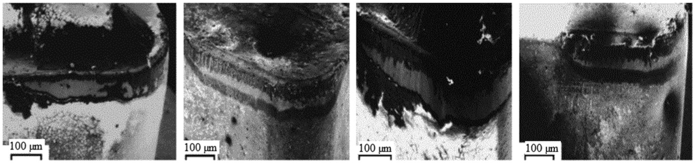
Flank wear of coated carbide cutting tools while machining of the 20 wt% Al2O3 particle-reinforced composites: 43 (a) TiN (K10) cutting tool: speed of 210 m/min, particle size of 32 µm; (b) TP30 cutting tool: speed of 210 m/min, particle size of 32 µm; (c) TiN-coated tool: speed of 100 m/min, particle size of 66 µm and (d) TP30 cutting tool: speed of 160 m/min, particle size of 16 µm.
The hardness of reinforcement particles in MMCs is similar to many cutting tool materials and much higher than that of matrix materials, so their abrasive nature causes flank wear. During machining of MMCs, flank wear is the main wear type that occurs on the flank faces of the tool, particularly for the TiN (K10)-coated tools, and the coating of the coated carbide tools is removed from the tools. The worn flank encouraged the adhesion of the workpiece material because of generating high pressure at the tool–workpiece interface. In addition to adhesive wear mechanism, abrasive wear also causes tool wear in the flank. Reinforced particles scratched and gauged away an aluminium alloy film when the grooves formed by abrasion on the tool face are filled with the workpiece material. As a result, the tool’s flank face will be protected against further abrasion by the adhering layer.36,44 The workpiece material adhesion was reported for the coated tools (by TiN). On the cutting edge, higher stress and temperature may also chip off the cutting edge. Abrasion process is observed at some places, while chipped tool materials between the tool’s flank face and the newly machined surface are ploughed. A smooth wear was also observed under the adhered layer on the flank face. The grooves are formed in consequence of loss of coated layer and sintered particles through aluminium seizure and pull-out process on the flank face. 36 Built-up edge (BUE) forms on the rake face of the tool at low cutting speed on a TiN (K10) tool. Since it protects the tool rake face from further abrasion, its formation is beneficial for tool life. The formation of BUE depends on cutting tool types and machining conditions. 11 The coating on cutting tool is thin, and it is damaged during the machining of MMCs; particularly at higher speed, the partial coating spalls and the cracks spread into the adjacent coating. Removal of coating from flank and rake faces of the tool leads to a smooth and uniform flank and nose wear. 36 In addition, thermal cracks also occur because of the combination of high temperature and adhesion wear. The removal of coating and mild cracking over the flank face are parallel and generated in the cutting direction. Multi-layered coatings are more wear resistant than a single-layered coating.43,45 During wet machining, the worn tool flank surface’s texture is nearly similar to that of dry machining case with parallel grooves; this similarity represents domination of two-body abrasive wear mechanism. During turning with coolant, three-body abrasion has been decreased because chips and formed abrasive powders, as a result of broken particulates, are removed using the cutting fluid. Therefore, cracks and pits which are caused by particulates on the cutting tool surface are not formed. 44
Effect of machining parameters
Machining parameters’ influence such as cutting speed, feed rate and DOC on tool wear has been studied by different researchers. 46 Cronjäger and Meister 47 found that with increasing cutting speed, the tool wear enhances while machining of particle- and fibre-reinforced MMC materials by polycrystalline diamond (PCD) tools. The formation of BUE was noted when the feed rate exceeded 0.6 mm/tooth. The trend of tool wear is not similar for machining short and continuous fibre reinforcements. For this reason, tool wear reduces by increasing feed rate for the continuous fibre, but it results in increasing the tool wear for short fibre reinforcements. The tool wear decreases because of the shorter contact time and way between the cutting edges and the hard and abrasive fibres or particles and formation of BUE. Similar observation was confirmed by Tomac et al. 28 who suggested that thermal softening of the composite at higher feed rate results in increase in the tool life. Moreover, abrasion of the tools reduces, since the workpiece material becomes softer and the SiC particles are pressed to the workpiece. A series of tests were conducted for studying the influence of cutting parameters on tool wear,36,48 and the results showed enhanced flank wear with the increase in DOC, which was attributed to enhanced abrasion by micro-cutting at the tool flank face. At higher feed rates, when material removal is fixed, there is lower contact between tool surfaces and the abrasive reinforcement in MMCs. Furthermore, formation of chips is changed by enhancing the feed rate. At lower feed rates, on the other hand, the chips are continuous, but these become discontinuous when feed rates and DOCs increase. 36 Higher feed rate decreases tool wear, by reducing contact between the cutting edge and the abrasive-reinforced particles.
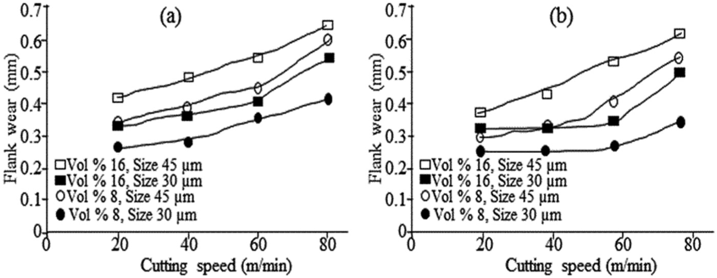
Karakaş et al. 49 also studied the effect of cutting speed in particulate metal matrix composite (PMMC) samples that were milled. Cutting speed directly affected the size and formation of BUE. In the cutting zone, temperature increased because of friction between tool and workpiece during machining. Higher temperature caused by higher cutting speeds results in softening and reduction in the adhered material on tool wear. In contrast, lower cutting speeds will reduce cutting zone temperature. This will cause strain hardening of aluminium; therefore, the removal of adhered material becomes very difficult. 39 At lower cutting speeds, higher performance of all the tools was possible because of BUE formation. The BUE acts as thin film between the tool and chips, which temporarily protects the tool surface from abrasive wear. 49 Figure 2 displays the effect of cutting speed on the tool wear. It shows that the increase in cutting speed enhances the tool wear.51,52
Flank wear of (a) uncoated and (b) coated carbide cutting tools after 1250 mm3 MMC removal. 50
The effect of machining parameters was investigated during machining of Al/SiC-MMC by Manna and Bhattacharayya. 53 They observed no BUE during machining of Al/SiC-MMC at high speed and low DOC. The wear pattern was regular flank wear, since reinforced particles in MMC act as abrasive. When the cutting speed is constant at 100 m/min, the effect of DOC on the tool wear is more significant than feed rate during machining of Al/SiC-MMC. A DOC of 0.25 mm gives 0.1 mm flank wear; when the DOC is double, that is, 0.5 mm, wear increases to 0.2 mm, that is, flank wear goes up to two times. Compared to cutting speeds, flank wear is less sensitive to the feed rate; therefore, increasing of feed rate is better than cutting speed during machining of Al/SiC-MMC. 53 In a similar study, Kılıçkap et al. 11 stated that increase in cutting speed leads to a faster tool wear. Feed has lower effect on tool wear at low cutting speed, and increase in feed rate enhanced tool wear slightly. At higher cutting speed, the feed rate’s influence was obvious, and tool wear enhanced with increase in feed rate. Sahin et al. 54 also confirmed the increase in tool wear with increase in cutting speeds at all test conditions. They concluded that during machining of coarse-particle composites, the cutting speed has more effect on tools’ life. Therefore, it is better to machine these kinds of composites at low cutting speed. Despite different discussions about the mechanism of the tool wear at different feed rates, all researchers recommend aggressive feed rates and DOCs during the roughing operations.36,55
Kannan and Kishawy 44 investigated flank wear at various cutting speeds for dry as well as lubricated conditions. The flank wear progress was very similar for both operating conditions up to the cutting speed of 120 m/min which indicates that the thermal effects are negligible in this range of speed. However, the application of coolant causes reduction in wear at higher cutting speeds, as the cooling effect decreases the cutting edge’s thermal load to a greater extent and thus adhesive and diffusive wears. Besides, at higher cutting speeds, the BUE formation is decreased during dry turning. The additives in the coolant acted as protective and lubricating layers and introduced cooling effect at the contact area between the tool flank region and workpiece, since it helps to reduction in friction and forces and leads to lower abrasive wear. Figure 3 shows improving tool life using emulsion as coolant.
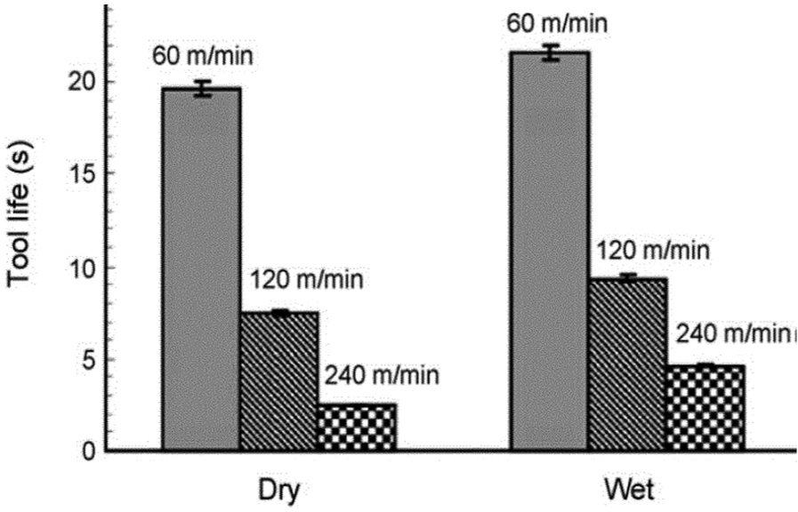
Effect of coolant and cutting speed on tool life of coated carbide tool. 44
Effect of reinforcements
Machining of composites is difficult because of the presence of hard ceramic particles in the composites that lead to rapid tool wear.56,57 For instance, the hard SiC particles in Al/SiC-MMCs act as small cutting edges when exposed intermittently to the tool surface. These particles act as abrasive between cutting tool and workpiece, which leads to high tool wear, poor surface finish and burr formation.57–59 It is known that the machinability of composites, with large size and high volume fraction of reinforcing particle, is poor. 60 The effect of the reinforcing particulates’ size is more than the population of reinforcing particles.56,61 The tool wear enhances when ceramic particle size increases during machining.45,54 It is probably due to shocking influence of coarse particles in the composites, since they are bigger than fine particles. Besides, these particles easily break because their brittleness is high. 54 Li and Seah 61 studied the machinability of MMC with different amounts of SiC, particularly the effect of size and fraction of particle reinforcement. When the fraction of reinforcement in the MMC is higher than a critical value, the abrasive wear accelerates. In addition to reinforcement particle size, the densities of the reinforcement and matrix have effect on the wear acceleration.61,62 The effects of SiCp reinforcement on AlSi7Mg2-MMC at different fractions on tool wear during turning were investigated by Ozben et al. 4 Tool wear decreases with increase in reinforcement fraction at low cutting speeds under constant feed rate and cutting depth. The higher wear of cutting tool was due to the abrasive nature of SiCp reinforcement. 62 The wear process at the rake face and clearance face of a cutting tool was classified as sliding wear by Weinert and König. 63 Tool wear occurs during machining because of direct contact between the particles and the cutting edge and their relative motion to the rake and clearance faces. Consequently, the reinforcement’s hardness is mentioned as the main parameter, which affects tool wear. According to the topographies of the worn cutting edges, Manna and Bhattacharayya 53 derived that the abrasion is the main tool wear mechanism.
Effect of machining on various tools
In recent years, machining processes are increasingly demanding upon cutting tool materials.50,54 Using tools with different coatings for machining of materials known as difficult-to-cut actually shows state-of-the-art machining technology. Coatings applied on cutting tools enhance lubrication at the tool/chip and tool/workpiece interfaces, which decrease friction; as a result, the temperature reduces at the cutting edge. In comparison to uncoated tools, coated carbide tools have better performance at higher cutting conditions during machining, since they have higher wear resistance, lower heat generation and lower cutting forces. Ciftci et al. 56 investigated tool wear of SiCp-reinforced Al-MMC, and the results showed that a longer tool life and a better surface quality are produced using coated and uncoated tools, respectively.
Quigley et al. 64 reported that during machining of the SiCp-reinforced composite, a triple-coated carbide with TiN as top layer, has the best performance in terms of flank wear, however, have the poorest surface finish. Monaghan and O’Reilly 57 stated that the coated carbide tools suffered excessive edge chipping and crater wear during machining of SiC/Al MMC. Sahin et al. 43 studied the machining of MMC with various volume fractions of Al2O3 particles by different tools. Other than broken layer of coated material of TiN (K10)-coated tool, formation of BUE along with flank wear was also noted. It can be concluded that a triple-layer coating has higher resistance than a double-coated layer based on the tool life. In comparison to uncoated tools, using coating on tools improves wear resistance in all cutting speeds. The coating of cutting tool reduces the flank wear as the coating makes the cutting tool surface harder. 11 An improved machinability of Al/SiC-MMC and reduced tool wear were reported by Sahoo et al. 65 during machining with inserts coated by multi-layer of TiN, TiCN and Al2O3. Other researchers have reported similar findings.66–68 Preference for using uncoated or coated carbide tools relies on whether tool wear or surface finish is the most important factor.
Results achieved by Looney et al. 60 during machining using different cutting tool materials showed that both coated and uncoated carbide tools sustained significant levels of tool wear after a very short period of machining. A cubic boron nitride (BN) insert because of its extreme hardness had the best performance, whereas the worst performance belonged to a silicon nitride (SiN) tool. During cutting of the different MMCs, the performance of the ceramic tool materials depends on the hardness of them. When hardness of tool is decreased, increase in wear for the materials softer than reinforcements is faster than harder material. Through cemented carbide tools with same hardness, those which contain the grades with lower binder and larger carbide grain size show better wear resistance compared to finer grain size or higher binder content. The wear characteristics are changed with the presence of ductile binder phase in the tool; for instance, the cemented carbide tool with only 3% of the binder did not behave like the ceramics. 69 The sintered cubic BN, produced by direct bonding of the hard phase grains, is much better than the cemented carbides. Only tool life of the diamond tools is reasonable, which strongly depends on the cutting speed. 70 Wear rate highly depends on hardness that shows abrasive wear is the main wear mechanism. Two general types of wear scars were observed on the coarse-grained diamond tools. 69 (1) At low cutting speed, wear scars are generated like lightly ground fractured surface. Mostly, the diamond grains’ size is bigger than surface features in this case. (2) Grooves or flats extending over a number of grains are observed in roughly polished surfaces generated. The fine-grain diamond tools wear out slower than the large-grain tools. During machining of sandstone using PCD tools, a similar phenomenon was observed. It was attributed to reduction in the fracture toughness of diamond while the temperature is enhanced. 69 Brun et al. 69 suggested that for decreasing the cutting temperature, which accelerates diffusion and adhesion wear and thermally weakens the tool, using lower cutting speeds is effective. Effect of polycrystalline cubic boron nitride (PCBN) and PCD tools at low and high cutting speeds during machining of Al/SiC-MMC workpiece was studied by Ding et al. 37 They reported that the lowest flank wear belongs to the binderless PCBN tools and, on the flank face, the main wear mechanism was related to surface cracking. Between all PCBN tools, the highest fracture resistance and wear resistance belong to binderless PCBN tools and PCD tools, respectively. Besides, PCD tools exhibited lower tendency for work material adhesion. During machining, the rake face of the cutting tool was subjected to intergranular fracture. While machining was performed with PCBN tools without coolant, the transfer material severity on the tools raised considerably with increase in cutting speed. Apart from the tool wear, adhesion between tool and the work material has major effect on the surface finish. The performance of PCD tools was better than PCBN tools due to their higher abrasion and fracture resistance and lower adhesion property with the work material. 37 The wear of PCD tools is affected by the tool rake angle, intensely. It could be because of greater cutting forces encountered with such a rake angle when flank wear increases in the case of negative rake angle. In addition, the produced chips, which cause damage to the tool surface, became caught between the tool and the workpiece. In the cutting edge zone, tools with positive rake angle indicated irregular flank wear and excessive pitting. For determining tool’s wear mode, the tool nose radius is an important factor. With decreasing tool nose radius, the tool was found to suffer from excessive chipping and crater wear. This tool chipping results in enhancing cutting forces and flank wear. So, small nose radius tools are recommended for finishing operations. Besides, it is expected that small nose radius yields better geometrical accuracy. 36
Surface integrity
The surface roughness is defined as combination of micro-geometry of the machined surface with surface texture. Although determination of surface roughness is hard via analytical equations, two main parameters are used to evaluate surface finish characterization: average roughness (Ra) and maximum peak to valley height (Rt). The following equations are used to calculate surface roughness for turning process39,71
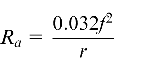
and

where f is the feed rate and r is the tool nose radius. Effect of other parameters on surface roughness, for instance, tool vibration or chip adhesion is not considered in the theoretical models. The machined surface integrity of Al/SiCp composite has been studied extensively by many experiments.39,72–76 There are a vast number of defects on the machined surface, such as voids around the SiC particles, SiC fracture or cleavage, and cavities due to pull out of SiC particles. Especially, when the volume fraction of SiC is relatively large, the surface quality is supposed to be deteriorated greatly, thereby leading to a more complicated formation process.
Typical machined surfaces of MMC materials are shown in Figure 4. During the process, some particles are pulled out from the machined surface because of debonding of reinforced particles from the matrix material. This causes many pits in the surface. The matrix around the particles might tear up, when the particles are pulled out or crushed.39,73,77 The particles size affects the depth of pits, which can be several hundred nanometres. Because of the detachment of SiC reinforcement from the matrix or rotation of the SiC reinforcement to adopt deformation of the matrix around it, the voids and microcracks were formed. The ploughed particles through the matrix materials’ surface for some distance cause grooves and scratches. Three categories of grooves (scratches) are formed by reinforcements: (1) grooves with uniform and shallow depth that are caused by the crushed or pulled-out SiC when it flowed to flank face with chip, (2) wider and deeper grooves due to indentation effect of reinforcements and (3) grooves due to ploughing of debonded particles through the matrix material. Some part of the fractured or pulled-out reinforcements trapped between flank face and machined surface interspaces and pressed into the matrix. 74 Because of the presence of rigid and brittle reinforcements, some dusty chips and other contaminations embedded into the machined surface. In addition to the repetition of tool geometries at intervals of feed per workpiece revolution, the machined surfaces are generated by tool–particle interaction too. 39 Matrix tearing occurs during surface generation when the cluster of reinforcements encountered by the cutting tool. Soft matrix may cover the pits and cracks due to the pressing effect of flank face of cutting tools. This is also a kind of surface defects due to weak bonding between matrix and reinforcement materials. Besides, because of the plastic flow of matrix material around the active cutting edge under sufficiently high pressure material, swelling is observed during machining.74,75
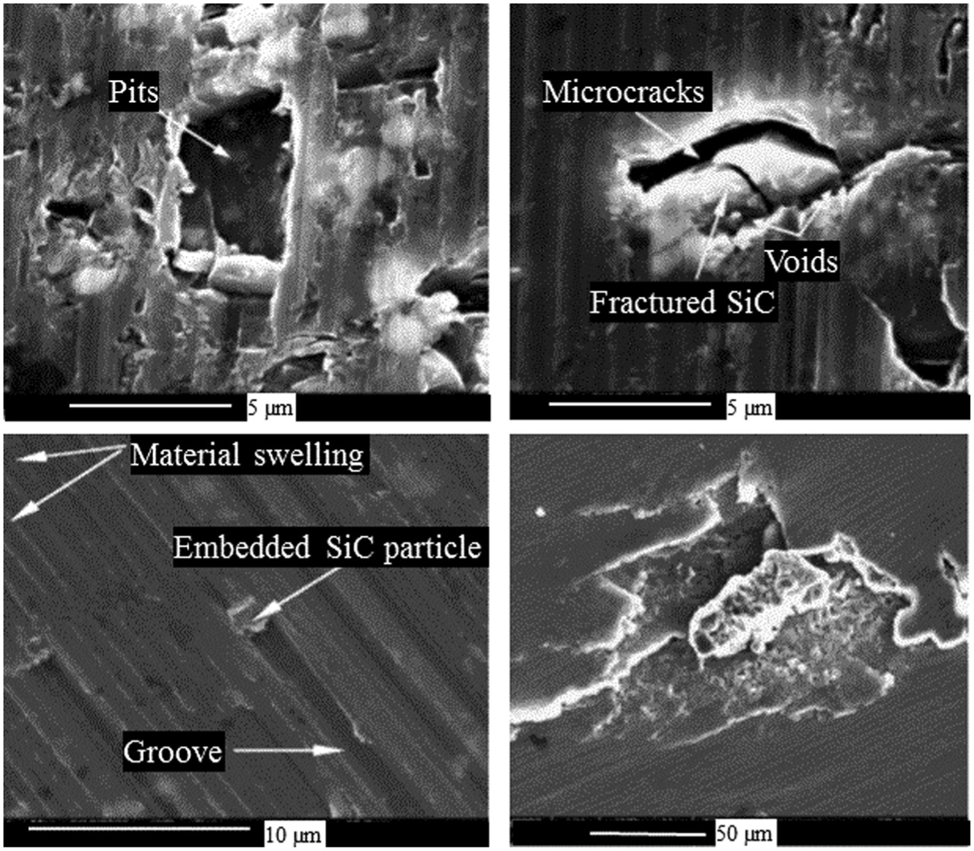
Machined surface of MMC material shows pits, microcracks, voids, fractured particles and material swelling, embedded reinforced particle and soft matrix covering the pits. 74
Effect of cutting parameters
According to different studies, the cutting speed, feed rate and DOC are important parameters, which affect surface quality significantly.71,78–80 El-Gallab and Sklad 73 studied type and form of surface and subsurface damage by changing cutting parameters during turning of Al/20%SiCp MMC. Figure 5 indicates the effect of different cutting parameters on the surface roughness (Rmax). It shows that the surface roughness reduces with the increase in feed rate. At low feeds, the surface roughness of the MMC was controlled by particle fracture or pull out; but at higher feeds, it was controlled by the feed. 39 It seems that the effect of particle fracture or pull out on surface roughness is significantly higher than that of feed in this case. 36 Figure 5(b) demonstrates the role of stable BUE in protection of tool from abrasion wear. At the highest cutting speed (v), feed rate and DOC, the surface roughness increases; in low feed rates and high DOCs, surface quality reduces, since the formed BUE is unstable. 73
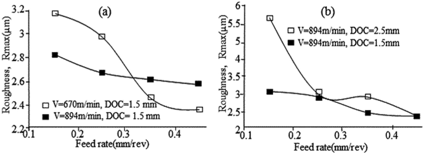
Surface roughness (Rmax) variation with increase in (a) cutting speed and (b) depth of cut. 36
In a study conducted by Ozben et al., 4 effect of increasing feed rate, while cutting speed and DOC are constant, on SiCp-reinforced aluminium MMC has been investigated. The results showed that surface roughness of machined specimens increases with increasing feed rate, which is also mentioned by other researchers.81–83 The effect of feed rate on surface roughness is contradictory to that described in Figure 5. This is due to the different sizes of the reinforced particles and range of feed used in these two studies. The microstructures of machined surfaces under different feed rates are shown in Figure 6. 75 It is obvious that by increasing feed rate, more B4C particles are pulled out and crushed, which results in poor surface quality.
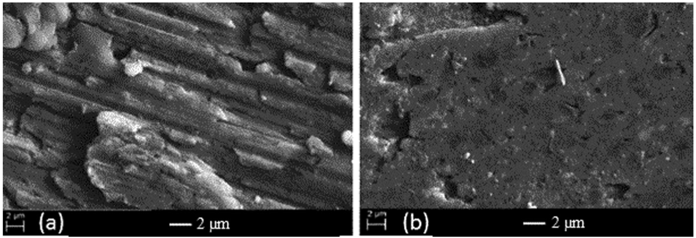
Surface finish boron carbide particle-reinforced aluminium MMC at (a) lower feed rate (0.1 mm/rev) and (b) higher feed rate (0.3 mm/rev). 75
When feed rate is constant, roughness increases with increase in chip depth, but it is not a significant change. 4 The variation of surface integrity (surface roughness, residual stress and morphology) by change of milling parameters on Al/65%SiCp was studied. 84 The highest and lowest influences on Ra belong to milling speed and axial DOC, respectively. After milling speed, interaction between milling speed and feed rate, then the feed rate, has highest influence on roughness. The results showed that increase in feed rate results in increase in surface roughness of Al/65%SiCp. It could be due to the variation of the pitch of the generated profile because of change in feed rate. Besides, at higher feed rates during high-speed milling, the amount of plastic deformation increases, which facilitates the formation of pits and tracks and worsens the surface quality. Changes of milling speed cause slight reduction in surface roughness. It can be attributed to reduction in milling force as a result of high temperature in high-speed milling that leads to higher flow ability of the aluminium matrix and increase in strain rate. So, the chances of SiC particles being cut are higher compared to pull out which results in decrease in pits and voids. Therefore, surface quality will improve. The highest effect on surface residual stress belongs to axial DOC, which is followed by milling speed and feed rate. When the feed rate increases, the residual stress rises, which leads to increase in tensile stress; but it does not happen when speed varies. Residual stresses are compressive for Al/65%SiCp, and surface texture is irregular with no regular feed marks. 84 The selected cutting parameters’ effect on surface roughness was measured by Kılıçkap et al. 11 The results indicated that a better surface was generated using low cutting speed; but by increasing the feed rate, the surface roughness rises. It is due to higher temperature in the cutting zone which is caused by higher feed rates that leads to decrease in bonding between SiCp and Al matrix. 11 Overall, the improvement of the surface finish with increased feed rate is considered due to the difference in properties of MMC compared with those of conventional alloys, particularly the base aluminium alloy. The MMC produces better surface finish at a faster feed rate, thus decreasing the manufacturing time yet maintaining a better surface quality product. Moreover, the interaction of the reinforcement particles with the machining operation may explain that the surface roughness of MMCs is larger than that of the base alloy at low feed rates but smaller than that of the base alloy at higher feed rates.39,75
Basavarajappa et al. 85 studied surface integrity of drilled holes when cutting parameters are changed. Figure 7 demonstrates the effect of feed rate and cutting speed on surface roughness while drilling samples by multifaceted carbide drill bit and conventional coated carbide drills, respectively. When feed rate and cutting speed are increased, the surface roughness increases and decreases, respectively. The surface roughness reduction with cutting speed increase could be due to the increase in burnishing and honing effects, which is caused by trapped SiCp between the tool and drilled hole. In addition, the reduced contact time between the tool and workpiece results in decrease in burnishing effect by increasing feed rate and increase in the surface roughness. 85 Other investigations confirmed results obtained by Basavarajappa et al. 85 Conversely, the surface roughness decreases, when cutting speed and DOC increase.33,71,86 A BUE, which is formed at low cutting speeds, vanishes with increase in cutting speed.87,88 As a result, chip fracture reduces, and therefore, the surface roughness decreases. The research results on drilling of 17 vol% SiC/2124 Al MMCs showed that the surface roughness reduces when feed rate increases at each spindle speed and all heat-treated conditions. Like other results, reduction in flank wears due to increase in feed rate causes this effect. The surface roughness increases in the high-speed steel (HSS) drills with increase in speed, but increase in the point angles leads to surface roughness reduction. 89
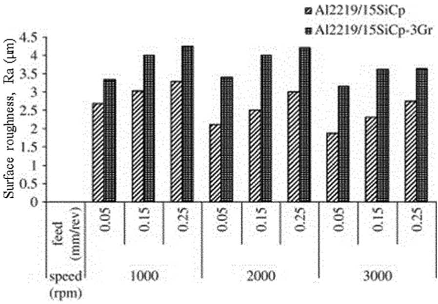
Variation of surface roughness versus cutting parameters for Al2219/15 wt% SiCp and Al2219/15 wt% SiCp-3Gr during drilling with carbide drill. 85
An experimental investigation on the machinability of Al/SiC-MMC during turning using fixed rhombic tools revealed that influence of cutting speed and feed rate was equal when both parameters are increased simultaneously. When DOC and cutting speed increase, cutting forces increase and decrease, respectively. 53 Looney et al. 60 observed that the surface roughness decreases by increasing nose radius or decreasing feed rate. The influence of BUE and the hard particles, which act as secondary cutting tools, results in poor surface. On the other hand, with increasing cutting speeds, the BUE breaks and tool nose radius increases, which improves surface finish. The process parameters’ influence on hardness of the machined surface and subsurface layer of matrix was studied by Kannan and Kishawy. 90 The obtained microhardness measurements’ results showed that the hardness is higher below the machined surface at lower cutting speed. With the increase in the cutting speed, this leads to increase in strain and the temperature, and the hardness decreases. The thermal gradients cause plastic deformation and material volume change. The effect of work hardening of matrix is the main factor in loss of strength, when the cutting speed is low that results in higher mechanical stress and lower heat generation. These parameters lead to the formation of a compression layer with higher hardness than the matrix. 90
The above paragraphs present contradictory results on effect of feed on the surface finish. Some researchers reported the increase in surface roughness with the increase in feed, but others reported the opposite trend. Generally, the surface roughness of monolithic alloy increases with the increase in feed. However, it is not the case for particle-reinforced MMCs, where the interactions among the cutting tool, machined surface and reinforced forced particles play additional roles on the roughness of machined surface. These interactions become significant at low feed compared to that at high feed. The damage to the machined surface is relatively low when the size and volume fraction of the reinforced particles are smaller. In that situation, the surface roughness of the machined MMC surface increases with the increase in feed. Nevertheless, the damage to the machined surface is significantly higher at lower feed when the size and volume fraction of the reinforced particles are higher. Therefore, the surface roughness of the machined MMC surface decreases with the increase in feed.
A research to study the influence of using coolant during cutting on the surface integrity of the machined material was done by Kannan and Kishawy. 90 The microhardness of matrix improves during wet cutting conditions. It could be attributed to reduced cutting temperature using coolant, which increases the work hardening of the 7075 matrix and leads to elimination of adhesion of the material on the cutting tool. Besides, using coolant during cutting, the BUE is not formed, and the depth of plastically deformed zone decreased. For significant decrease in cutting temperature and BUE formation during wet cutting, the chances of producing peak tensile residual stresses are lower. They reported no metallurgical phase changes on the subsurface, and the main mode of subsurface damage is plastic deformation of the aluminium matrix under both dry and wet cutting conditions. However, during wet cutting, the most of the particulate damages were in form of pull out. 90 The cutting fluid flow rate does not have significant effect on the surface quality. 91
Effects of reinforcement particles
A study by Pramanik et al. 39 showed the effect of reinforcement particles on surface integrity. They observed an increase in surface roughness with increase in feed rate for the both reinforced and non-reinforced materials. At lower feed rates, particle fracture or pull out controls surface roughness, but it is controlled by feed at higher feed rates. Interaction of the reinforcement particles with the cutting tool results in compressive residual stresses on the machined surface, which reduce with increasing feed rate. The speed had no significant effect on the residual stress of the MMC. Pendse and Joshi 92 observed that the surface roughness will be affected significantly by reinforcement volume if the tool nose radius be comparable to the reinforcement size in the composite material; otherwise, it does not have effect on the process, as shown schematically in Figure 8. They predicted that the reinforcement particles lay along the surface profile if the tool nose radius was much larger than reinforcement particles’ size (Figure 8(a)). Still, the reinforcement particles will interfere with the surface finish even if it is equal or smaller (Figure 8(b)). The experimental result of a study by Basheer et al. 18 confirms the phenomena that happen in the precision machining of composites. If the feed rate, tool nose radius and reinforcement size are at their maximum level, then the reinforcement size can be compared with the surface asperities’ height and will interfere with the produced surface roughness. Thus, it is concluded that reinforcement size affects the surface roughness of machined composite material when it is comparable to the feed rate and the tool nose radius.
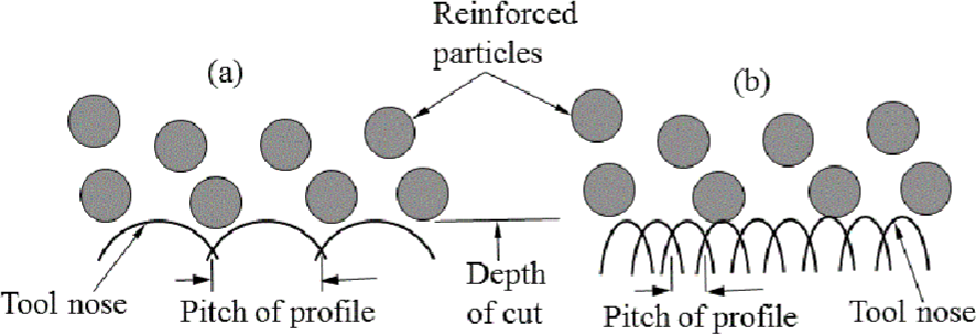
Reinforcement size and surface roughness when tool nose radius is (a) larger than the particles size and (b) equal or smaller than the particles size. 92
In another research, Tosun and Muratoglu 89 studied the influence of reinforcement size on the surface roughness of composite materials. The plastic deformation occurrence is obstructed by particulates when their size increased which results in stress gradients around the particles. As a result, surface roughness increases because of formed defects. The microhardness variations of 6061 Aluminium were investigated by Kannan and Kishawy. 90 They reported that particle spacing increases when the average particle size increases in a constant volume fraction. The particles act as a barrier during flow of the aluminium matrix and restrain the plastic flow of the matrix. These result in plastic localization of the aluminium material between the particles and decrease in depth of plastically deformed zone. Consequently, the microhardness under machined surface increases because of the inhomogeneous plastic deformation of the ductile aluminium matrix with higher volume fraction of ceramic particles. Ozben et al. 4 investigated the effect of reinforcement percentage by measuring surface roughness (Ra). According to them, samples with higher reinforcement ratio have higher surface roughness compared to the samples with lower reinforcement ratio. Therefore, it could be said that increase in particle ratio influences surface roughness negatively.4,93–95 On the other hand, increase in reinforcement percentage improves hardness and tensile strength of composite material.96,97
Simulation of machined surface
Ramesh et al. 98 conducted a transient dynamic finite element (FE) analysis for investigating the mechanics of the turning process of Al6061/SiCp composite with diamond cutting tools. The four possible interactions between the tool and the materials were studied: (1) tool facing SiC phases, (2) tool facing Al matrix, (3) tool ploughing through SiC phases and (4) tool ploughing through Al matrix. For simulating the orthogonal machining process of Al/Al2O3 composite, Zhu and Kishawy 99 developed a plane–strain thermo-elasto-plastic finite element model (FEM), considering the interface failure between aluminium matrix and Al2O3 particles. Specific interest was on distribution of the contact stress and the interface failure. Pramanik et al. 100 studied the matrix deformation and tool–particle interactions in simulation with ANSYS/LS-DYNA software. Three categories were determined for encounters of tool with particle reinforcements: particles along, above and below the cutting path. Dandekar and Shin 101 established a multi-step three-dimensional (3D) FEM by AdvantEdge and ABAQUS Explicit to predict the subsurface damage when the particle-reinforced MMCs are machined. For simulation of the extent of particle–matrix debonding, interface layer was modelled by cohesive zone elements. A random particle dispersion algorithm was used for randomly distributed particles in the matrix. A homogeneous FEM model was developed by Zhou et al. 102 for predicting the cutting force behaviour of Al/SiCp composite with large particle size and high volume fraction by ABAQUS Explicit software. In addition, a micro-FE model was built as well to analyse mechanism of removing the SiC particles and the internal stress distribution. Fathipour and colleagues103,104 built two-dimensional FEMs to simulate the cutting process of low-volume fraction particle-reinforced MMCs with ABAQUS Explicit software. Both chip formations and machining force were studied. The surface generation on machined MMCs from the FE analysis is presented in Figure 9. 105 It is concluded that localized surface hardening of machined MMC is caused by the particles’ indentation because of interaction between particles (located immediately below the cutting edge) with the tool. The matrix is deformed plastically to a greater depth in these areas. Newly generated surfaces are under compressive residual stress. The pull out of particles, located at the lower part of the cutting edge that has interaction with the cutting tool, causes cavities on the surface. The hard particles fully or partly are debonded because of failure of alumina particle’s interface. These debonded particles slide over cutting edge and tool faces and scratch the contact surfaces. Thus, during machining of MMCs, high tool wear is observed. When the fracture of reinforcements is not included in the machining simulation, continuous shallow cavities and deep discontinuous cavities are noted on the newly generated surfaces. Two reasons are responsible for the generation of shallow cavities. First, the reinforcements are pulled out from the matrix, and second, the movement and rotation of reinforcements occur inside the matrix as the tool advanced. The big discontinuous cavities are caused by the movement of reinforced particles with the tool and indentation of the particles in the surface during generation. The occurrence of large cleavage, plough through and micro-fracture is demonstrated by including particle fracture in the simulation. 105
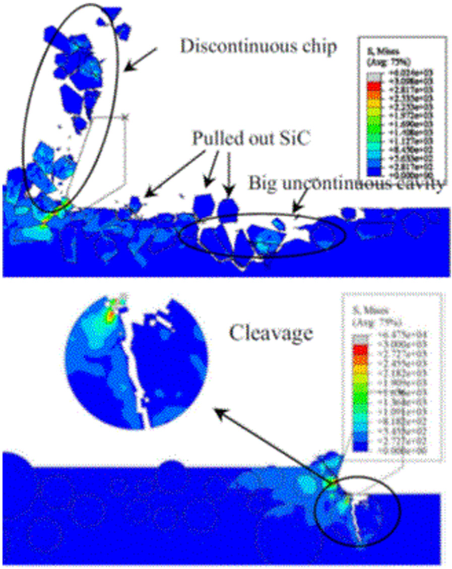
Machined surface generation in MMCs by finite element analysis. 105
Conclusion
The above investigation gives details of tool wear and surface generation during machining of MMCs. It also discusses the effect of different input parameters as well as material properties on tool wear and surface finish. Based on the above analysis, the following conclusions are drawn. These will provide valuable guidelines to researchers as well as industry people to design cutting tool and machining parameters to reduce the cost and improve efficiency of MMC machining:
Cutting speed has the highest effect on tool wear among the machining parameters. The tool wear increased with increasing the cutting speed in all the cutting conditions. The feed rate is the second influential machining parameter on tool wear. Higher feed rates produced a higher tool wear. Tool wear increases slightly at higher DOC.
The coated tool performs better than the uncoated one in terms of low tool wear and improved dimensional accuracy.
Increasing of reinforcement volume fraction increases tensile strength and hardness of MMC material and cutting tool’s flank wear. The increase in particle volume fraction has negative effects on roughness. It seems that the tool hardness influences the surface roughness and the harder carbide tools produce better surface finish compared to that of HSS and the TiN-coated HSS drills.
Coolant increases cutting tools’ lifespan and affects the matrix microhardness. The depth of subsurface plastic deformation reduces with the application of coolant.
Higher cutting speed gives better surface finish. Contradictory results on the effects of feed rate on the surface finish are available. At low feeds, the surface roughness of the MMC was controlled by particle fracture or pull out; but at higher feeds, it was controlled by the feed. Particle volume fraction and average size profoundly affect the extent of plastic deformation of the matrix material. The lower the volume fraction and coarser the particles, the higher will be the microhardness variations beneath the machined surface. The volume of reinforcement could influence the surface roughness significantly if the tool nose radius is comparable to that of the size of reinforcement in the composite material. The size of reinforcements in the composite material influences roughness of the machined surfaces significantly when its magnitude is comparable to that of the feed rate and the tool nose radius employed during machining of the composite material.
The most contributing factor to surface residual stress is axial DOC compared to speed and feed rate. With the increase in feed rate, the surface residual stress tends to increase and becomes tensile stress. On the other hand, reinforcement particles in MMCs induced compressive residual stresses on the machined surface because of their interaction with the cutting tool. The influence of speed on the residual stress of the MMC was not significant.
Footnotes
Declaration of conflicting interests
The author(s) declared no potential conflicts of interest with respect to the research, authorship and/or publication of this article.
Funding
The author(s) received no financial support for the research, authorship and/or publication of this article.