
Abstract
In this study, by cutting electrical steel stator laminations, one of the most important components of electrical machines by different cutting methods, the effects of these cutting methods on motor efficiency are investigated. As cutting methods, wire electrical discharge machining, punching, laser and abrasive water jet methods are used. Burr formation at the cutting edge leads to short circuits during the steel packaging and causes magnetic losses in steel packages to increase. In addition, depending on the cutting methods, electrical steel lamination insulation layer is damaged as a result of residual and thermal stress formations. These negative conditions cause iron, friction and windage, stator, rotor and additional load losses occurred in the engine to decrease. In order to minimize these cases, electrical steel stator laminations are cut with the cutting parameters determined as a result of pre-cut tests and 5.5-kW induction motors are manufactured. These manufactured motors, according to IEC 60034-2-1-1B method, are subjected to no-load performance tests in addition to six different loading ratios of 25%–50%–75%–100%–115%–125% and constant 50 Hz frequency. As a result of the test measurements, losses occurred in electrical steels cut with abrasive water jet are found to be higher than the other cutting methods. In addition, in terms of the motor performance, the best results are obtained with wire electrical discharge machining cutting method.
Introduction
Reducing the electricity consumption in terms of energy saving and protection of the nature has critical importance throughout the world. Motors are used widely in electrical devices particularly in industrial applications. Reducing the energy consumption during the usage of these devices has a great importance. Non-grain-oriented electrical steels are used widely in the structures of transformers and the core of motors (stator and rotor). In reducing energy losses in motors, electrical steels having low iron losses should be selected. Cores are formed by pressing electrical steels with different geometries after cutting them with different cutting methods. 1 In order to manufacture stator and rotor sheets in high volumes and cutting speeds, punching method is reasonable in terms of costs. For prototype purposes or small quantities, electrical steels are also cut with different methods like laser cutting method. In these cutting methods, changes in microstructure occur due to the stresses formed on the cutting edges. This affects the magnetic properties of the electrical steels negatively.2–5 As an alternative, abrasive water jet (AWJ) and wire electrical discharge machining (WEDM) are also used for small quantities and prototype production purposes. AWJ cutting method is effective for minimizing the formation of deformation as well as its cooling effect created at the cutting edge. 6 With the WEDM, cutting process is performed by creating crater on the material with the help of electrode wire. Regional high temperatures occurring in the cutting zone cause the coating material on the electrical steel to burn and a decrease in the magnetic properties. 7 In particular, irregularities in flux distribution, heat and short circuits formed in the electrical steels in the stator cores as a result of these negative situations created in the cutting region and caused by the cutting methods decrease the electrical motor efficiency. 8
Induction motor efficiency is determined by the ratio of output power to the input power. This measuring method is also known as direct measurement method. Alternatively, motor efficiency can be determined by the method of summation of losses using input power. This measurement method is also known as the separation of losses in the standards. If the stray load losses are fully determined, using the summation of losses, method to measure motor efficiency becomes more accurate. 9
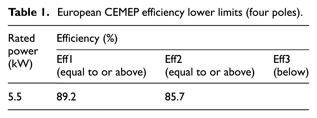
European Union countries, members of CEMEP (European Committee of Manufacturers of Electrical Machines and Power Electronics), categorized electrical motors in terms of their efficiency classes. Efficiency classes of induction motors used in industrial areas are determined by CEMEP member countries as follows:10,11
Eff1 class: “High-efficiency” motors
Eff2 class: “Efficiency improved” motors
Eff3 class: “Low efficiency” motors
Electric motor manufacturers perform motor efficiency measurements in terms of the procedures determined according to international standards.
It was detected that in literature, the laminated magnetic properties of electrical steel stator and rotor sheets cut using different cutting methods were mostly analyzed using Single Sheet Tester (SST), Epstein Frame and Toroid measuring methods. Cutting methods’ effects on magnetic induction and frequency-dependent hysteresis and eddy current losses, magnetic flux density and magnetic permeability were determined. However, unlike the other studies, the stator sheets, which were cut using the punching, laser, AWJ and WEDM cutting methods, were packaged by welding with electric arc welding, and induction motors were manufactured in this study. Accordingly, the cutting methods’ effect on efficiency of the electric motors already used in industrial applications was examined. Thus, the data obtained as a result of this study shall be a guide to electric motor manufacturers, which carry on a business in industry.
In this study, stator steels of the induction motor whose limit efficiency values are shown in Table 1 are cut with laser, AWJ, WEDM and punching, and the effects of these cutting methods on the motor efficiency are investigated. Motor performance tests are performed according to indirect measurement method determined in IEC 60034-2-1-1B standards and the performance results are analyzed in detail.
European CEMEP efficiency lower limits (four poles).
Determination of motor efficiency
Direct method
Electric motor works on the basis of the conversion of electrical force into the mechanical power. During this process, a decrease takes place in motor efficiency depending on the losses. According to IEC 60034-2-1 standards, induction motor efficiency is measured with two different methods as direct and indirect measurements. In the direct measurement method, motor efficiency
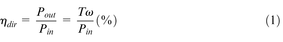
According to equation (1),
Indirect method
Indirect measurement method is used to determine the components creating the losses in electric motor in addition to the input and output power. It is also known as the summation of losses. 9 Indirect measurement method is expressed in international standards as IEC 60034-2-1-1B and calculated according to equations (4) and (5)
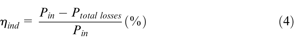
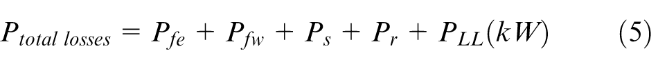
Here,
Motor efficiency in direct measurement method is determined according to the input and output power while it is determined according to the losses in indirect method. Motor is loaded with dynamometers in both measurement methods. Using velocity, torque, voltage, current, power factor and input power values, motor efficiency can be calculated easily by validating the torque and input power. In many international standards, it is expressed that the motor should be run until it reaches to the thermal equilibrium state in order to measure motor efficiency accurately. During the test, if the motor temperature is not changing more than 1 °C in the last half hour during the test, it is assumed that the thermal equilibrium is achieved. Time to reach thermal equilibrium varies depending on the motor size.9,15
Experimental procedure
Sample preparation and cutting methods
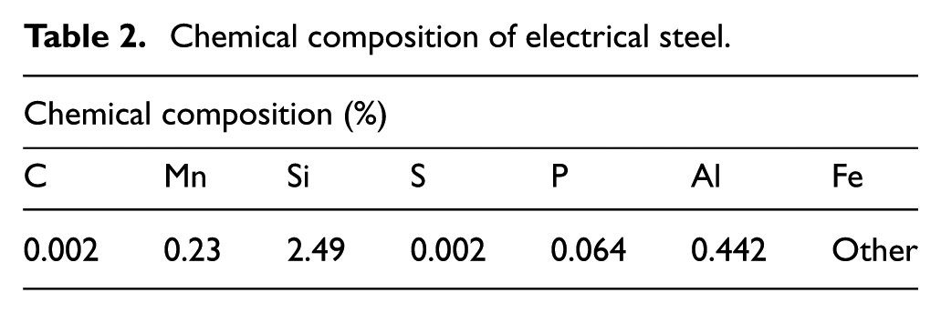
In the tests, M400-50A cold rolled non-grain-oriented electrical steel having 0.5-mm thickness and whose chemical composition is given in Table 2 and manufactured by SC Erdemir is used. Electric stator steel of the induction motor with 5.5-kW power is manufactured by WEDM, punching, laser and AWJ, and the rotor steel sheets are manufactured by only punching (Figure 1). Thus, the effect of the cutting methods on the motor efficiency is determined by considering the stator sheet.
Chemical composition of electrical steel.
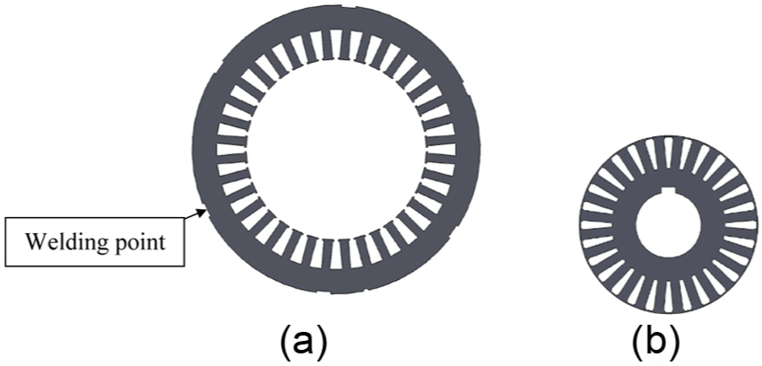
Electrical steel structures for 5.5-kW induction motor: (a) stator and (b) rotor sheet.
In order to manufacture electrical stator steels with different cutting methods precisely, the cutting parameters used are determined by performing the pre-cutting experiments. Accordingly, for WEDM, the wire diameter of 0.25 mm, wire feed rate of 9 m/mm, pulse interval time of 13 ms, pulse duration of 14 ms, wire tension of 1600 g and wire tensile strength of 1000 N/mm2 are determined; for punching, clearance of 5% is determined; for laser, N2 cutting gas, cutting power of 6000 W, cutting speed of 8.6 m/min, cutting pressure of 15 bar, focal length of 9.8 mm, nozzle diameter of 1.4 mm, beam quality of 1.82 M2 and wavelength of 10.6 µm are determined; and for AWJ, water pressure of 3700 bar, cutting velocity of 850 mm/min, abrasive particle size of 80 mesh, abrasive hardness of 8 Mohs and the consumed abrasive amount is determined as 250 g/min. In addition, average surface roughness of the cut electrical steel (µm) is found in the evaluation about the surface conditions by Mahr Perthometer monitoring tip roughness device.
Electrical stator steel laminations manufactured according to each cutting method are pressed with 20 MPa stress and then combined with and electric arc welding through six sewing channels at equal intervals (Figure 2(a)). Welding process is performed by coated alloy steel wire electrode in 3.5 mm diameter and 125 A parameters. After cutting rotor sheets with punching, rotor bars are cast with aluminum die casting method. In order to prevent axial deviation, rotor sheet package is mounted onto the rotor shaft and machined together (Figure 2(b)). Stator sheet package is mounted onto the aluminum body and then the winding process is performed. After varnishes are made for ensuring the insulation between copper wires, motors are heated for 9 h in an oven at 155 °C. With the installation of rotor package into the body with the mechanical connection equipment (bearing, ring, key, outer and inner bearing caps), motors were ready for efficiency tests (Figure 2(c)).
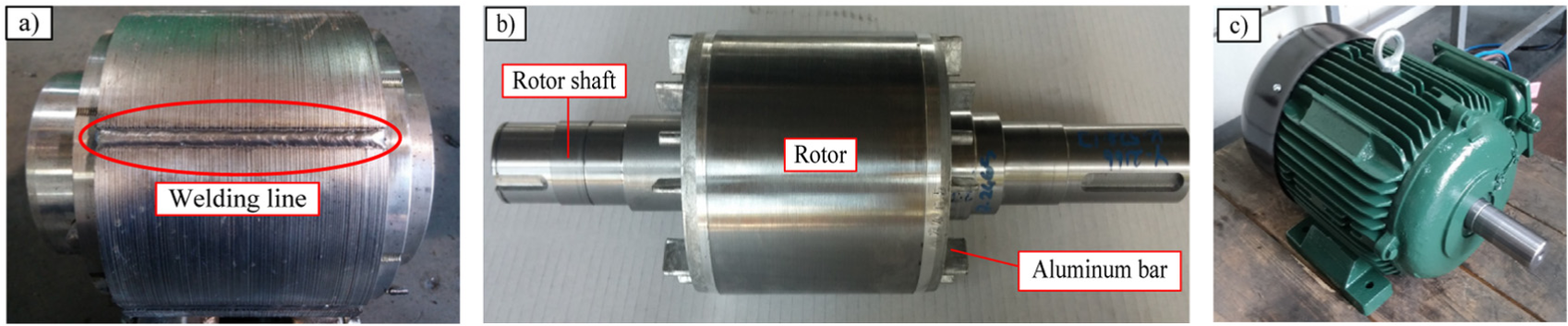
Induction motor manufacturing steps: (a) stator welding screw, (b) rotor sheet package and (c) induction motor.
In the experimental analysis, 5.5-kW, three-phase, four-pole and fan cooled (380 V, 50 Hz, 1500 r/min) induction motors are used. Tests were performed according to the summation of losses method determined in IEC 60034-2-1-1B standards. The experimental setup used for the tests is shown in Figure 3.
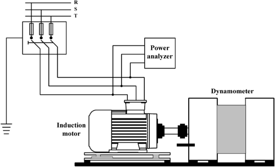
Basic scheme of test setup.
In order to measure electrical and mechanical variables in high-precision, power analyzer (Hioki-3390) is used. A dynamometer (Schenk) is used for loading electrical motor in fixed or variable values. Torque and velocity measurements with dynamometer are performed by load cell and encoder, respectively.
Results and discussion
Motor efficiency is determined as per loaded and no-load tests in international standards. The majority of motors used in industrial area are loaded at about 60% of the nominal load. However, in this study, to determine the efficiency of 5.5-kW induction motor, loaded and unloaded tests (25%–50%–75%–100%–115%–125%) are applied. For this purpose, since iron, friction and windage losses are independent of the load, loaded tests were performed to determine no-load, stator, rotor and additional load losses.
The results obtained from the tests are given in Figure 4 and Table 3. According to Figure 4(a), motor efficiency is determined to increase for up to nominal loading rate for all cutting methods in 50 Hz fixed frequency value. In particular, motor efficiency in nominal loading (100%) reaches to the maximum level. Under the nominal load values, motor efficiencies manufactured by WEDM, punching, laser and AWJ cutting methods are measured as 85.61%, 85.16%, 83.47% and 83.1%, respectively. Motor efficiency is observed to decrease over the critical loading values (115% and 125%). Many motor manufacturers design their products to obtain maximum efficiency according to approximately 75% loading point for the needs of the consumers. However, in order to prevent load fluctuations that may occur in the motor, motor design is made so that more loading can be done. 14
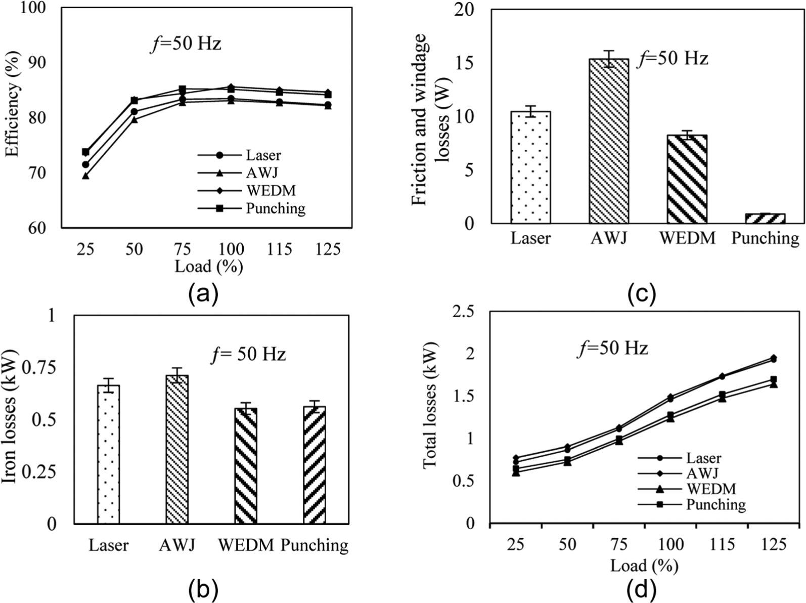
Test results for induction motor: (a) efficiency–load relation, (b) iron losses–cutting method relation, (c) friction and windage losses–cutting method and (d) total losses–load relation.
Comparison of motor efficiencies and losses for cutting methods.
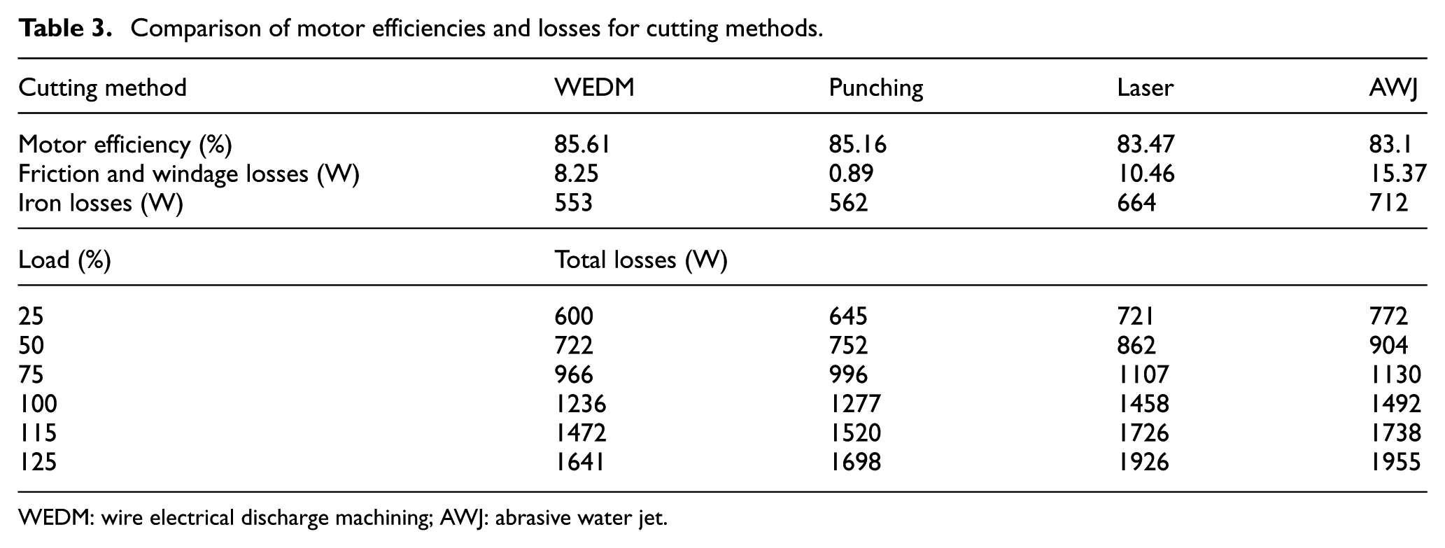
WEDM: wire electrical discharge machining; AWJ: abrasive water jet.
Iron, friction and windage losses measured as a result of no-load tests are given in Figure 4(b) and (c). Iron losses are measured as 712 W in AWJ, 663.92 W in laser, 562.25 W in punching and 553 W in WEDM methods. At the cutting edge of the electrical steels cut with punching, plastic deformation is observed at about 22 µm height due to rounding depending on the residual stresses (Figure 5(a)). Plastic deformation causes insulation layer at the sheet edge to damage and to decrease its magnetic properties.4,5,8,16–19 Furthermore, the average surface roughness (Ra = 0.77 µm) is observed to be lower than the other cutting methods.
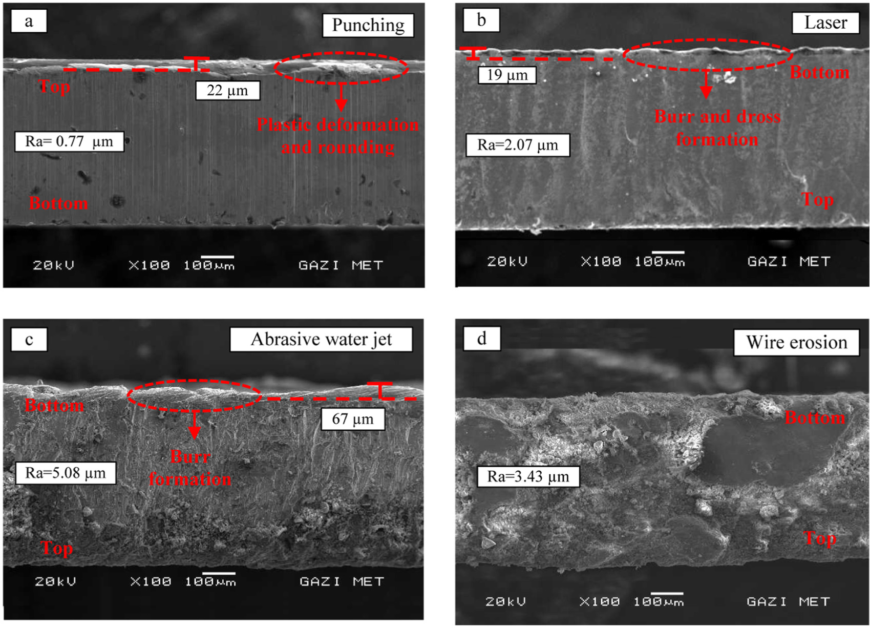
SEM image of surface structure on cutting edge.
At the cutting edge of electrical steel laminations cut by laser, in addition to the thermal stresses due to heat, melt material is solidified and forms burr and dross with average 19 µm height (Figure 5(b)). Thermal stresses formed via heat effect cause an increase in hardness at the cutting edge of electrical steels, changes in the grain structure and a decrease in the magnetic properties.2,20–25 This situation causes motor efficiency to decrease (Figure 4(a)). In the cutting surface, it is determined that fluctuation occurs due to heat and gas pressure, and accordingly, the average surface roughness is 2.07 µm (Figure 5(b)).
At the cutting edge of the electrical steels cut by the AWJ, plastic deformation depending on the residual stresses as a result of the high fluid pressure together with the abrasive particle occurs.26–28 At the bottom surface of the cutting edge of the plastic deformation, burr formation is observed with the height of 67 µm (Figure 5(c)). Burr formation has the effect of increasing the iron losses between the packaged steels and the damage of the insulation layers. The iron losses occur on the steel package in the form of heat depending on the short circuit lines formed between electrical steels. This affects the motor efficiency negatively. The average surface roughness (Ra = 5.08 µm) formed in the sheets cut by AWJ is determined to be more than that of the other cutting methods.
The heat formed due to the electrical current at the cutting edge of the electrical steels manufactured by the WEDM method causes the formation of thermal stresses. Due to thermal stresses, insulation layer located in the cutting region of the electrical steels is damaged. However, since the cutting process is performed in coolant fluid, the effect of these stresses on the magnetic properties occurs less than the laser cutting method. On the cut surfaces, Cu and Zn elements on the wire electrode material composition are observed to adhere on the cutting surface by dissolving due to the heat8,29,30 (Figure 6). This leads the cutting surface to be porous and an increase in the surface roughness (Ra = 3.43 µm; Figure 5(d)).
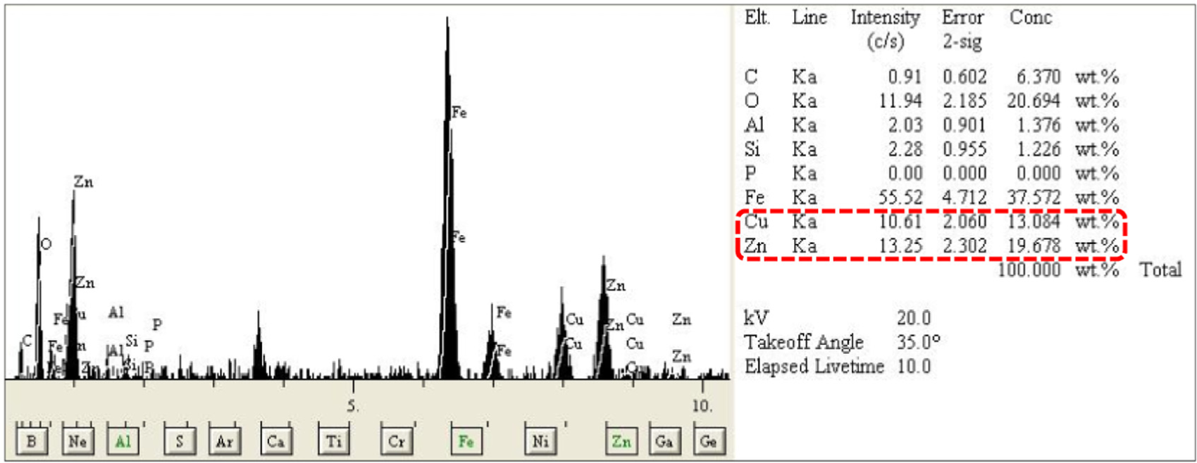
EDS profile of electrical steel to cut with WEDM.
As a result of the no-load tests, friction and windage losses are measured as 15.37 W in AWJ, 10.46 W in laser, 0.89 W in punching and 8.25 W in WEDM (Figure 4(c)). In order to minimize the friction and windage losses, it is required to determine the working clearance between the stator and rotor in an optimum way, to fix the air gaps that may occur due to burrs between electrical steels and to use the appropriate insulation for the stator windings. Moreover, these losses can be minimized by designing an ideal cooling fan, bearing selection for rotor shaft and by optimizing the manufacturing tolerances. Stator losses are the losses formed depending on the current and the resistance in the stator windings. Rotor losses, on the contrary, are the losses formed due to the air gap and shift impact. In Figure 4(d), total losses formed in the motor depending on the loading are shown. Accordingly, with the increase in the motor loading rates for all cutting methods, total losses (stator, rotor and additional load losses) increased. 14
In Figure 5(a), it was determined that plastic deformation and rolling occurred on shear edge. Material absorbs a little energy when it undergoes plastic deformation. This absorbed energy leads to the formation of microstructural defects on shear edge. 31 These defects affect the mechanical properties of the material on shear edge and also the magnetic domain structure and domain-wall motion during magnetization process. 32 In Figure 5(b), it was determined that thermal stress, burr and slag occurred on shear edge, and surface waving occurred on the surface, depending on heat and cutting gas pressure. Local melting and rapid re-crystallization occurred on shear edge because of the heat effect. This situation changes the crystal lattice structure on shear edge of the material, and reduces magnetic properties of electrical steel sheets by causing the microstructure change. 33
In Figure 5(c), formation of plastic deformation and burr was observed on shear edge depending on fluid pressure, as well as abrasive particles. Furthermore, formation of oxidation was determined on the surface because of the fluid effect.
In Figure 5(d), it was determined that Cu and Zn elements, among electrode wire components, adhered to shear edge under the influence of electric current and refrigerant. Furthermore, oxidation formation on shear edge, which resulted from the fluid, was determined using energy-dispersive X-ray spectroscopy (EDS) analysis. Under the influence of electric current, thermal stresses occurred on shear edge because of heat effect. Under the influence of thermal stresses, coating material undergoes partial combustion on shear edge. This situation reduces the motor efficiency of electrical steel sheet, as well as its magnetic properties. 7 In Figure 5, the data obtained for all the cutting methods are parallel with the studies done in the literature. However, 255 pcs stator sheets were cut in this study to form motor stator sheet package for each cutting method. Spaces due to the burr height of 255 sheets used while forming stator sheet package, even if at micro-level, for single electrical steel sheet piece, burr and slag, rolling and plastic deformation, which formed on shear edge. These spaces cause the formation of short circuit ways and increase in iron losses between stator sheets. In the event of the increase in iron losses, motor efficiency decreases. In Figure 5, even if plastic deformations at micro-level for single sheet piece are not considered significant for 1 pcs sheet, and when stator sheet package consisting of 255 pcs sheets is considered, the effect of those reaches the macro level in terms of motor efficiency.
Electric motor manufacturers mainly use punching method to cut stator and rotor sheets during mass production. However, due to the high cost of mold manufacture for cutting stator sheets in prototype or special-purpose motors manufacture, it is necessary to use alternative cutting methods. For this purpose, the WEDM, AWJ and laser cutting methods are preferred. In this study, it was determined that the highest motor efficiency was in WEDM cutting method by 85.61% and the lowest motor efficiency was in AWJ cutting method by 83.1%. Accordingly, when the efficiency difference of 2.51% between both cutting methods is evaluated in terms of annual service life of the motor, this has importance in terms of both increasing market share of the producing enterprises and contributing to energy conservation of the consumer enterprises. In an enterprise where a large number of electric motors are used, even slight increases in motor efficiency shall help reduce the manufacturing costs of the enterprises.
Conclusion
Motors are manufactured by cutting the electrical steels used for packaging the stator and rotor sheets of the electric motors with different cutting methods. During the cutting process, microstructure and hardness changes as well as the residual and thermal stresses on the cutting surface cause the magnetic properties of the electrical steels to decrease. In addition, due to the burr formation at the cutting edge depending on plastic formation, iron losses increase during the electrical steel packaging and the short circuit lines occur between the sheets. These cases due to the cutting methods have negative impact on the electric motor efficiency.
In this study, stator sheets of a 5.5-kW induction motor are manufactured by cutting with laser, AWJ, WEDM and punching. The effects of the cutting methods on the motor efficiency are determined according to IEC 60034-2-1-1B (summation of losses) test method. The results obtained from the tests are listed below:
The best motor efficiency is obtained as 85.61% with WEDM, and the lowest motor efficiency is obtained as 83.1% with the AWJ method. In addition, in punching and laser cutting methods, motor efficiencies are measured as 85.16% and 83.47%, respectively.
Motor efficiency is observed to be affected by the plastic deformation and residual stresses in punching and AWJ method and by the thermal stresses in the WEDM cutting method.
Total losses in all loading rates (stator, rotor, friction and windage losses, iron and additional load losses) are measured in the motors whose stator sheets are manufactured with AWJ, laser, punching and WEDM with a descending order.
Motor efficiency for all cutting methods reached to the maximum level of 100% loading and decreased in the 115% and 125% critical loading rates.
In the electrical steels cut, average surface roughness is measured as 0.77 µm for punching, 2.07 µm for laser, 3.43 µm for WEDM and 5.08 µm for AWJ. In general, motor efficiencies are higher in the cutting methods having less surface roughness.
Burr and dross formations are found to increase iron losses between the electrical steels and affect the motor efficiency negatively.
This study will be a guide for determining the best cutting method for the manufacturers in the prototyping and mass production of electrical motors.
Footnotes
Acknowledgements
The authors would like to thank TUBITAK for their contributions as the PhD thesis promoting scholarship as well as with the “Project No. 214M610.”
Declaration of conflicting interests
The author(s) declared no potential conflicts of interest with respect to the research, authorship and/or publication of this article.
Funding
The author(s) received no financial support for the research, authorship and/or publication of this article.